Materials for the Hydrogen Economy (2007) Episode 8 docx
Bạn đang xem bản rút gọn của tài liệu. Xem và tải ngay bản đầy đủ của tài liệu tại đây (2.05 MB, 30 trang )
186 Materials for the Hydrogen Economy
and has been used to create permeation barrier coatings on steels. One consideration
is the temperature required for the process relative to heat treatment temperatures of
steels. The treatment temperature of the MANET-II ferritic-martensitic steel limits
the process temperature to about 750˚C, which in turn limits the amount of alumi
-
num and depth of diffusion of aluminum in the surface. For this case, hot dipping
was chosen as a preferred method.
41
Permeation reduction factors of up to 10,000, or 10
4
, have been realized with the
best coatings based on aluminized steels. Ferritic-martensitic steels that were alu
-
minized had the Fe
2
Al
5
phase predominant in the layer sequence, while a 316L steel
had FeAl
3
and FeAl
2
as the main aluminide phases.
25
The best permeation barrier
resulted from an external alumina lm of about 1 micron in thickness grown on the
aluminide layers.
25
The vacuum evaporation process and polymer slurry process are quite new rela-
tive to the others and have the potential to provide more control in the processing,
in the case of the vacuum evaporation technique, or greatly reduce the cost and
environmental concerns of pack aluminizing with the polymer slurry methods. The
vacuum evaporation process allows one to diffuse other elements than Al into the
steels or to deposit FeAl coatings directly onto the surface of the steels, with Al dif
-
fusion occurring to help bond the deposited coating.
39
This process is referred to as enclosed vacuum evaporation (EVE) coating tech-
nology and is applicable to a variety of coating and substrate materials, with a unique
capability of producing smooth and uniform coatings on the inner surface of small-
diameter, high aspect ratio cylindrical components or other conned geometries.
Atomic Percent Aluminum
0 10 20 30 40 50 60 70 80 90 100
0 10 20 30 40 50 60 70 80 90 100
1600
1538°C
1400
1394°C
1200
1000
912°C
800
770°C
600
400
Fe
Weigt Percent Aluminum
Al
L
660.452°C
1310°C
(_Fe)
(aFe)
1232
1169°C
~1160°C
1102°C
FeAl
Fe
3
Al
Fe
2
Al
5
FeAl
3
655°C
(Al)
¡
Temperature °C
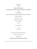
FIGURE 8.1 AlFe phase diagram showing intermetallic phases, such as FeAl
3
, Fe
2
Al
5
,
FeAl
2
, and FeAl, which can form as separate layers in aluminized steel.
5024.indb 186 11/18/07 5:53:06 PM
Hydrogen Permeation Barrier Coatings 187
The technique has been used to deposit reproducible coatings on the inner surface of
tubes as small as 10 mm in diameter and in lengths up to 3.8 m. For larger-diameter
tubes or pipes in which radiant heating of the substrate from the source lament is
impractical, separate resistive or inductive heating of the substrate to the desired
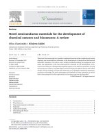
temperature is used. Figure 8.2 shows the inner surface of a steel tube coated with a
FeAl alloy for hydrogen barrier testing. The deposition is rapid, and substrate tem
-
perature rise can be controlled to avoid de-tempering alloys.
The polymer slurry method for aluminizing steel surfaces is straightforward and
simple, and should be low cost since the raw materials and processing steps are also
low cost. Aluminum ake of 1 to 2 microns in diameter is blended with a preceramic
polysiloxane polymer and heated in air or nitrogen to 700 to 800˚C for several hours
to allow the aluminum to diffuse into the steel and to allow an external Si-Al-O lm
to form from reactions between the siloxane backbone and the Al. As with all alumi
-
nizing reaction–diffusion coatings, a series of aluminide layers form on the surface
of the steel, as shown in gure 8.3. The outermost layer of alumina is the hydrogen
permeation barrier, while the aluminum-rich layers provide additional aluminum for
alumina formation in oxidizing environments, as required to maintain the external
oxide layer.
The advantages of aluminizing steels go beyond hydrogen barrier formation,
however, as such surface treatments also provide additional corrosion protection.
The fusion materials community continues to study these processing methods and
may continue to be the main driving force for research in this area until hydrogen
infrastructure issues become more important.
27
FIGURE 8.2 FeAl coating on the inner diameter of a 316SS tube that was deposited using
the EVE technique.
5024.indb 187 11/18/07 5:53:08 PM
188 Materials for the Hydrogen Economy
8.5 SUMMARY
The best hydrogen barrier coatings have been fabricated using aluminized steels
produced by a variety of methods, including pack aluminizing, hot dipping, vacuum
evaporation, or polymer slurry techniques. Permeation reduction factors of up to
10
4
have been realized in this manner. Titanium-based coatings offer an alternative
choice to Al but are not as permeation resistant as the alumina-based methods, and
are not as reproducible in fabrication. Much work remains to be done in the general
area of hydrogen permeation barriers, particularly in the development of new meth
-
ods that can provide barriers over large areas for anticipated hydrogen economy
infrastructure needs. Low-cost methods and better reproducibility are required.
Hydrogen remains an elusive species in this regard, and a perfect solution is appar
-
ently very challenging.
REFERENCES
1. Forcey, K.S. et al., Hydrogen transport and solubility in 316L and 1.4914 steels for
fusion reactor applications,
Journal of Nuclear Materials, 160, 117–124 (1988).
2. Gibala, R. and R.F. Hehemann, Eds.,
Hydrogen Embrittlement and Stress Corrosion
Cracking, ASM, Metals Park, OH, 1984, p. 324.
3. Honeycombe, R.W.K., Steels: microstructure and properties, in
Metallurgy and Materi-
als Science, R.W.K. Honeycombe and P. Hancock, Eds., London: Edward Arnold, 1981.
FIGURE 8.3 A typical aluminized steel surface following the polymer slurry method at
800˚C in air. Any of the methods mentioned in this section about aluminized lms will pro-
duce similar reaction layers. Ease of processing and cost may dictate which method is pre-
ferred for a given application.
5024.indb 188 11/18/07 5:53:09 PM
Hydrogen Permeation Barrier Coatings 189
4. Hollenberg, G.W. et al., Tritium/hydrogen barrier development, Fusion Engineering
and Design, 28, 190–208 (1995).
5. Roberts, R.M. et al., Hydrogen permeability of sintered aluminum oxide,
Journal of the
American Ceramic Society, 62, 495 (1979).
6. Yu, G.T. and S.K. Yen, Determination of the diffusion coefcient of proton in CVD
gamma aluminum oxide thin lms,
Surface and Coatings Technology, 166, 195 (2003).
7. Serra, E. et al., Hydrogen permeation measurements on alumina,
Journal of the Ameri-
can Ceramic Society, 88, 15 (2005).
8. Brimhall, J.L., E.P. Simonen, and R.H. Jones,
Data Base on Permeation, Diffusion,
and Concentration of Hydrogen Isotopes in Fusion Reactor Materials, Fusion Reactor
Materials Semiannual Progress Report, DOE/ER-0313/16, 1994.
9. Forcey, K.S. et al., Hydrogen transport and solubility in 316L and 1.4914 steels for
fusion reactor applications,
Journal of Nuclear Materials, 160, 117 (1988).
10. Hollenberg, G.W. et al., Tritium/hydrogen barrier development,
Fusion Engineering
and Design, 28, 190 (1995).
11. Perujo, A. and K.S. Forcey, Tritium permeation barriers for fusion technology,
Fusion
Engineering and Design, 28, 252 (1995).
12. Mühlratzer, A., H. Zeilinger, and H.G. Esser, Development of protective coatings to
reduce hydrogen and tritium permeation,
Nuclear Technology, 66, 570 (1984).
13. Yamada-Takamura, Y. et al., Hydrogen permeation barrier performance characteriza
-
tion of vapor deposited amorphous aluminum oxide lms using coloration of tungsten
oxide,
Surface and Coatings Technology, 153, 114 (2002).
14. Song, R.G., Hydrogen permeation resistance of plasma-sprayed Al
2
O
3
and Al
2
O
3
-
13wt% TiO
2
ceramic coatings on austenitic stainless steel, Surface and Coatings Tech-
nology, 168, 191 (2003).
15. Tazhibaeva, I.L. et al., Hydrogen permeation through steels and alloys with different
protective coatings,
Fusion Engineering and Design, 51/52, 199 (2000).
16. Forcey, K.S. et al., Formation of tritium permeation barriers by CVD,
Journal of
Nuclear Materials, 200, 417 (1993).
17. Shan, C. et al., Behaviour of diffusion and permeation of tritium through 316L stainless steel
with coating of TiC and TiN + TiC,
Journal of Nuclear Materials, 191–194, 221 (1992).
18. Van Deventer, E.H. and V.A. Maroni, Hydrogen permeation characteristics of some
Fe-Cr-Al alloys,
Journal of Nuclear Materials, 113, 65 (1983).
19. Earwaker, L.G. et al., Inuence on hydrogen permeation through steel of surface oxide
layers and their characterisation using nuclear reactions,
IEEE Transactions on Nuclear
Science, NS-28, 1848 (1980).
20. Fazio, C. et al., Investigation on the suitability of plasma sprayed Fe-Cr-Al coatings as
tritium permeation barrier,
Journal of Nuclear Materials, 273, 233 (1999).
21. Forcey, K.S., D.K. Ross, and L.G. Earwalker, Investigation of the effectiveness of oxi
-
dised Fecralloy as a containment for tritium in fusion reactors,
Zeitschrift fur Physika-
lische Chemie Neue Folge, 143, 213 (1985).
22. Shen, J N. et al., Effect of alumina lm prepared by pack cementation aluminizing
and thermal oxidation treatment of stainless steel on hydrogen permeation,
Yuanzineng
Kexue Jishu/Atomic Energy Science and Technology, 39, 73 (2005).
23. Aiello, A. et al., Hydrogen permeation through tritium permeation barrier in Pb-17Li,
Fusion Engineering and Design, 58/59, 737 (2001).
24. Glasbrenner, H., A. Perujo, and E. Serra, Hydrogen permeation behavior of hot-dip
aluminized MANET steel,
Fusion Technology, 28, 1159 (1995).
25. Forcey, K.S., D.K. Ross, and C.H. Wu, Formation of hydrogen permeation barriers on
steels by aluminising,
Journal of Nuclear Materials, 182, 36 (1991).
5024.indb 189 11/18/07 5:53:10 PM
190 Materials for the Hydrogen Economy
26. Fukai, T. and K. Matsumoto, Surface modication effects on hydrogen permeation in
high-temperature, high-pressure, hydrogen-hydrogen sulde environments,
Corrosion
(Houston), 50, 522 (1994).
27. Konys, J. et al., Status of tritium permeation barrier development in the EU,
Fusion
Science and Technology, 47, 844 (2005).
28. Glasbrenner, H. et al., Corrosion behaviour of Al based tritium permeation barriers in
owing Pb-17Li,
Journal of Nuclear Materials, 307–311, 1360 (2002).
29. Glasbrenner, H. et al., Development of a Tritium Permeation Barrier on F82H-mod, in
Sheets and on MANET Tubes by Hot Dip Aluminising and Subsequent Heat Treatment,
Forschungszentrum Karlsruhe GmbH, Karlsruhe, Germany, 1998, p. 30.
30. Glasbrenner, H. et al.,
The Formation of Aluminide Coatings on MANET Stainless
Steel as Tritium Permeation Barrier by Using a New Test Facility, Vol. 2, Elsevier,
Lisbon, 1997, p. 1423.
31. Iordanova, I., K.S. Forcey, and M. Surtchev, Structure and composition of aluminized
layers and RF-sputtered alumina coatings on high chromium martensitic steel,
Materi-
als Science Forum, 321–324, 422 (2000).
32. Iordanova, I., K.S. Forcey, and M. Surtchev, X-ray and ion beam investigation of alu
-
mina coatings applied on DIN1.4914 martensitic steel,
Nuclear Instruments and Meth-
ods in Physics Research, Section B: Beam Interactions with Materials and Atoms, 173,
351 (2001).
33. Forcey, K.S. et al., Use of aluminising on 316L austenitic and 1.4914 martensitic steels
for the reduction of tritium leakage from the NET blanket,
Journal of Nuclear Materi-
als, 161, 108 (1989).
34. Yao, Z.Y. et al., Hot dipping aluminized coating as hydrogen permeation barrier,
Acta
Metallurgica Sinica, 14, 435 (2001).
35. Aiello, A., A. Ciampichetti, and G. Benamati, An overview on tritium permeation bar
-
rier development for WCLL blanket concept,
Journal of Nuclear Materials, 329–333,
1398 (2004).
36. Aiello, A. et al.,
Qualication of tritium permeation barriers in liquid Pb-17Li, Fusion
Engineering and Design, 69, 245 (2003).
37. Benamati, G. et al., Development of tritium permeation barriers on Al base in Europe,
Journal of Nuclear Materials, 271/272, 391 (1999).
38. Perujo, A., K.S. Forcey, and T. Sample, Reduction of deuterium permeation through
DIN 1.4914 stainless steel (MANET) by plasma-spray deposited aluminum,
Journal of
Nuclear Materials, 207, 86 (1993).
39. Knowles, S.D. et al., Method of Coating the Interior Surface of Hollow Objects
, U.S.
Patent 6,866,886
, 2005.
40. C.H. Henager, Jr., Low-cost aluminide coatings using polymer slurries, personal com
-
munication, 2006.
41. Serra, E., H. Glasbrenner, and A. Perujo, Hot-dip aluminium deposit as a permeation
barrier for MANET steel,
Fusion Engineering and Design, 41, 149 (1998).
5024.indb 190 11/18/07 5:53:11 PM
191
9
Reversible Hydrides
for On-Board
Hydrogen Storage
G. J. Thomas
CONTENTS
9.1 Introduction 191
9.2 Hydride Properties and Hydrogen Capacity 192
9.3 Alanates 197
9.4 Borohydrides 200
9.5 Destabilized Borohydrides 201
9.6 Nitrogen Systems 202
9.7 Other Materials 204
9.8 Summary 205
References 205
9.1 INTRODUCTION
In concept, reversible hydrides offer a direct means of storing hydrogen on-board
fuel cell vehicles and would be compatible with a hydrogen-based transportation fuel
infrastructure. A tank, or perhaps more accurately a storage system, containing an
appropriate hydride material would remain xed on a vehicle and could be refueled
simply by applying an overpressure of hydrogen gas. Once lled, the hydrogen gas
would remain at the equilibrium pressure for the particular hydride material, chang-
ing only with temperature changes induced in the storage tank. When hydrogen was
needed, it would be released endothermically, using the waste heat from the fuel cell
(or internal combustion engine [ICE]) to supply the required energy. This approach
offers certain advantages over high-pressure compressed gas tanks and cryogenic
liquid hydrogen systems—it is inherently stable with regard to hydrogen release,
it can operate at a low or moderate gas pressure, and it could eliminate some of
the energy costs of compression or liquefaction. It also has the potential to achieve
volumetric hydrogen densities much higher than those of compressed gas and even
liquid hydrogen.
In practice, however, the use of hydrides for on-board hydrogen storage is much
more complicated than is described above, and a number of issues arise when one
attempts to choose a material and design a storage system. These issues arise because
(1) many hydride materials do not meet minimal on-board storage requirements for
5024.indb 191 11/18/07 5:53:12 PM
192 Materials for the Hydrogen Economy
weight and volume density, and (2) there are some fundamental material properties
that determine system performance that are competing against one another; that is,
they affect system requirements in opposing directions. Thus, a hydride-based storage
system will likely be a design with numerous trade-offs in terms of capacity, kinetics,
and thermal requirements. Furthermore, there are a host of other issues beyond capac
-
ity and kinetic performance, such as hydride–dehydride cycling-induced changes or
degradation in performance, response of the material to impurities in the incoming
hydrogen gas, evolution of impurities from the bed affecting the fuel cell, and, impor
-
tantly, cost of the material and its impact on the fuel supply system cost.
The development of storage materials with properties that can encompass all
of the required performance attributes for on-board hydrogen storage will be an
extremely challenging task and likely require a multidisciplinary approach. In 2003,
the U.S. Department of Energy (DOE) launched a concerted effort to develop high-
capacity materials that have the potential to meet the hydrogen storage system per
-
formance targets established by the DOE and FreedomCAR and Fuel Partnership
1
a government/industry collaboration. This hydrogen storage initiative has spawned
a considerable level of effort over the last few years, and it is in this arena that this
chapter will focus.
There have been many review articles on metal hydrides, and a few of the more
recent ones are referenced here.
2–10
This review will attempt to cover only fairly
recent studies on high hydrogen capacity hydrides that (1) have been demonstrated to
be reversible or, at the least, partially reversible and (b) have the potential for exhib
-
iting other properties (e.g., kinetics, operating temperatures) suitable for on-board
hydrogen storage applications. This area of materials research and development is
very active at the present time, so that it is likely that not all of the relevant work will
be included. The author apologizes for any omissions.
9.2 HYDRIDE PROPERTIES AND HYDROGEN CAPACITY
Hydrides can be loosely categorized by their chemical binding—metallic, covalent,
ionic, or complex—between the host elements and hydrogen. Intermetallic alloys
form a large class of hydrides, generally with metallic bonds, that can be further
subcategorized by the ratio of the alloying constituents A and B. Thus, for example,
one refers to LaNi
5
H
6
as an AB5 hydride. An online database of hydride properties,
hydpark,
11
is largely organized along these lines. From an on-board hydrogen stor-
age perspective, however, it is the nature of the chemical bond that is key because it
determines the thermodynamic stability of the hydride, the hydrogen stoichiometry
of the material, and the mechanisms for hydrogen absorption and release.
In 2001, Schlapbach and Zuttel published a paper on hydrogen storage
4
and
included a plot of volumetric and gravimetric hydrogen densities in a variety of
materials. Figure 9.1 shows a similar plot that also includes corresponding values
for compressed gas and liquid hydrogen, as well as the DOE and FreedomCAR and
Fuel Partnership targets for on-board storage systems. One can see that there are a
number of materials that contain hydrogen concentrations well above the system tar
-
gets, with some having more than twice the density of liquid hydrogen. In addition to
5024.indb 192 11/18/07 5:53:13 PM
Reversible Hydrides for On-Board Hydrogen Storage 193
mixing material properties with system properties, the plot also includes many dif-
ferent material types, such as solid reversible hydrides, liquid and solid nonreversible
chemical systems, and, for comparison, a few liquid and gaseous fuels (e.g., octane,
methane, etc.) plotted in terms of their hydrogen content.
One can notice some trends in material properties from the plot. First, the inter
-
metallic hydrides (plotted in bright red), such as LaNi
5
H
6
, generally have low gravi-
metric hydrogen density and are clustered toward the left-hand side of the graph.
But these materials are also relatively dense, and so they can have high volumetric
hydrogen densities, often greater than 100 g H
2
/l. A few elemental hydrides (also
plotted in bright red), such as MgH
2
and TiH
2
, are also shown. Although they may
exhibit high hydrogen densities, they tend to be heavy as well and, in many cases,
have strong covalent hydrogen bonds resulting in more stable structures. Their
higher stability means that higher temperatures are required to release the hydro
-
gen. For example, MgH
2
must be heated above 300°C in order to release hydrogen
at a signicant rate.
The highest-capacity materials (shown in blue on the plot) lie in the upper-right-
hand quadrant and above the system target lines. This chapter will be limited to a
discussion of these materials only because they are the materials that are of greatest
interest for hydrogen storage applications. Also, the chapter will not cover histori
-
cal developments and will largely be concerned with research published within the
last several years. One additional limitation in scope is that only material proper
-
ties related to the thermally induced release of hydrogen will be described. Other
hydrogen release reactions, such as hydrolysis, that generate an oxide or hydroxide
by-product that must be processed off-board will not be discussed.
The solid, reversible hydride materials plotted in blue in gure 9.1 generally con
-
tain an Al–H complex anion (alanates), a B–H complex anion (borohydrides), or
N–H groups (amides, imides). The plot also includes some nonreversible materials,
such as ammonia borane, NH
3
BH
3
, that have very high hydrogen capacities that can
be released by thermolysis, but must be regenerated through a chemical process.
This means that the spent fuel must be removed and processed externally. These
“chemical hydride” materials will also not be discussed in this chapter.
In intermetallic systems, hydrogen absorption (desorption) is relatively straight
-
forward and occurs through (1) molecular dissociation (recombination) at the metal
surface and (2) atomistic diffusion of the hydrogen through the solid. Grochala and
Edwards
8
refer to these materials as interstitial hydrides since the hydrogen resides
in the interstices of the metal lattice. In contrast, hydrogen dissociation in complex
hydrides generally occurs through the formation of intermediate compounds. The
reverse processes, the re-formation of the hydride phases, as well as hydrogen trans
-
port mechanisms, are generally not well understood in these materials. An addi
-
tional issue with the high hydrogen capacity materials is that they are often quite
stable and require high temperatures for hydrogen release.
The desired form of a reversible hydride reaction for on-board storage may be
written as
M
X
H
Y
+ heat ≡ XM(s) + Y/2H
2
(g) (9.1)
5024.indb 193 11/18/07 5:53:13 PM
194 Materials for the Hydrogen Economy
where M is a single element or combination of elements. The heat term on the left
side of the reaction indicates that the dissociation of the hydride coupled with the
release of hydrogen is endothermic, and conversely, formation of the hydride by
reacting the element(s) with gaseous hydrogen is exothermic. From the perspective
of a vehicular hydrogen storage system then, the material remains stable on-board
the vehicle at low or moderate hydrogen pressures until heat is applied. The preferred
source of this heat is waste heat from the fuel cell or ICE, so that there would be no
energy penalty for releasing the hydrogen. Ideally then, the operating temperature
range of the storage material should lie within the operating temperature range of the
fuel cell or ICE coolant loop.
It should also be noted from equation 9.1 that heat must be dissipated when refu-
eling the tank (recharging the spent hydride), and for refueling rates equivalent to
lling conventional gas tanks, the cooling power could, for the more stable hydride
materials, exceed the capacity of on-board coolant systems. In these cases, there
would be an energy cost borne by the off-board refueling facility.
The thermodynamic parameters of the reaction quantify the energy require-
ments. The Gibbs free energy of formation per mole of hydride at constant tempera-
ture, T, is
∆G
f
= ∆H
f
– T∆S (9.2)
Hydrogen Densities of Materials
0
50
100
150
200
0 5 10 15 20 25 30
Hydrogen mass density (wt. %)
Hydrogen volume density (gH
2
/L)
100
liquid
hydrogen
700 bar
350 bar
CH
4
(liq)
C
2
H
5
OH
C
8
H
18
C
3
H
8
C
2
H
6
NH
3
CH
3
OH
Mg
2
NH
4
LaNi
5
H
6
FeTiH
1.7
MgH
2
KBH
4
NaAlH
4
NaBH
4
LiAlH
4
LiBH
4
AlH
3
TiH
2
CaH
2
NaH
2015 system targets
2010 system targets
NH
3
BH
3
(3)
NH
3
BH
3
(2)
NH
3
BH
3
(1)
Mg(OMe)
2
.H2O
11M aq NaBH
4
hexahydrotriazine
decaborane
LiNH
2
(2)
LiNH
2
(1)
FIGURE 9.1 Plot of hydrogen weight fraction and hydrogen volume density for some rep-
resentative hydrogen storage materials. For comparison, the current 2010 and 2015 DOE/
FreedomCAR and Fuel Partnership targets for system weight and system volume densities are
indicated by the dashed lines. The densities of compressed hydrogen at ambient temperature
and liquid hydrogen at 20K are also shown.
5024.indb 194 11/18/07 5:53:15 PM
Reversible Hydrides for On-Board Hydrogen Storage 195
where ∆H
f
is the formation enthalpy of the hydride and ∆S is the change in entropy of
the system when the hydride is formed. When ∆G
f
is negative, the reaction is favored
and heat is released as the hydride is formed.
For an ideal gas, the hydrogen overpressure, P, in equilibrium with the hydride
at temperature T, can then be expressed in the form
12
RTln(P/P
o
) = ∆G
f
= –∆H
f
+ T∆S (9.3)
where R is the gas constant and P
o
is the pressure at standard conditions, that is,
1 atm of pressure. The enthalpy is expressed as the formation energy per mole of
hydrogen. The entropy change is the difference between the entropy of hydrogen
gas and the congurational and vibrational entropy of the hydrogen in the solid, and
is generally considered to have roughly the same value for most hydrides. One can
then readily see from the equation that the more stable a hydride is (larger ∆H
f
), the
lower the equilibrium pressure is at a given temperature. The equation also shows
that a plot of lnP vs. 1/T for a given hydride is a straight line with a slope of ∆H
f
/R,
the familiar van’t Hoff plot. Graphically, the Y-intercept at 1/T
→ 0 corresponds to
an equilibrium pressure at innite temperature.
Current research toward developing high hydrogen capacity materials for on-
board storage applications is largely concentrated on reducing the energy require
-
ments, either by modifying the material to reduce the enthalpy of formation, ∆H
f
, of
the hydride phase, or through altering the reaction pathway to hydrogen dissociation
or recombination. This stems largely from the on-board need to use the waste heat
from an “engine” (e.g., a fuel cell or ICE) to supply the required energy for hydrogen
release from the hydride. Roughly speaking, this means that the “operating window”
in temperature and pressure for a hydride storage system lies between room tempera
-
ture and 100°C, and ~1 and 100 bars. An examination of the hydpark database
11
indi-
cates that the bulk of experimental values for ∆S range from about 95 to 130 J/mol
H
2
. A simple calculation, then, using equation 9.3 would show that ∆H
f
should be
in the range of about 20 to 40 kJ/mol H
2
. The lower enthalpy values would actually
be preferred in order to reduce the cooling power requirements during rehydriding.
Even lower ∆H
f
materials, e.g., ~15 kJ/mol H
2
, could be used with higher-pressure
containers. However, materials with formation enthalpies higher than the upper limit
could not be used as storage materials because the operating temperatures would be
too high for on-board systems as they are currently envisioned.
Concurrently, the hydrogen kinetics of absorption and release must also be
improved to meet minimal performance standards through, for example, the devel
-
opment of effective catalysts or the formation of very small particle sizes (e.g.,
nanoscale materials). Of course, an added requirement for small particle sizes is that
their small dimensions be maintained through repeated hydride–dehydride cycling.
The kinetic requirements for hydrogen release in a storage material are dictated by
the needs of the vehicle driver and the fuel cell power. For example, a 100-kW peak
power fuel cell with about 42% fuel efciency would need 2 g H
2
/sec to produce full
power when demanded by the vehicle driver. Furthermore, this hydrogen delivery
rate must be available through nearly all of the range of the hydride composition.
5024.indb 195 11/18/07 5:53:16 PM
196 Materials for the Hydrogen Economy
This is a particularly severe requirement for a material when it is nearly depleted (the
fuel tank is nearly empty).
Hydrogen transport in the high-capacity hydrides appears to be through the
movement of heavy atoms, complexes, or lattice defects rather than hydrogen atoms,
with correspondingly higher activation energies for diffusion than for interstitial
hydrides. In Ti- and Zr-doped NaAlH
4
and Na
3
AlH
6
, for example, Sandrock et al.,
13
Luo and Gross,
14
and Kiyobayashi et al.
15
all measured activation energies for hydro-
gen release in the range of 80 to 100 kJ/mol. These high enthalpy values translate
to slower diffusion rates, and hence slower release rates, at the desired operating
temperatures. As an example, an increase in the activation energy for migration of
~25 kJ/mol reduces the diffusivity by a factor of 10
–4
. Since the diffusion distance is
proportional to (diffusivity × time)
½
, a diffusing species would then take 100 times
longer to travel the same distance out of a particle. Hence, one approach considered
to mitigate the slower transport rates is to reduce the particle size of the material.
For the above example, an equivalent release rate with the slower diffusivity could
be achieved by reducing the hydride particle size, for example, from 10 to 0.1 µm. Of
course, on an absolute scale, particles may have to be in the nanosize range to exhibit
sufciently fast kinetics.
In summary, the ideal reversible hydride would simultaneously have all of the
desired properties discussed above, as well as additional properties, such as good
stability through multiple hydride–dehydride cycles. The values derived in the pre
-
ceding text are compiled in table 9.1. It must be emphasized that these values do
not represent a comprehensive analysis, nor do they reect the DOE/FreedomCAR
and Fuel Partnership hydrogen storage system targets.
1
They are intended only to
highlight some of the hydride material properties from the perspective of hydrogen
storage system needs.
The hydride weight and volume densities were simply chosen so that a reason
-
ably designed storage system could meet or exceed the current 2010 FreedomCAR
and Fuel Partnership system targets. The actual energy densities for a specic system
would depend not only on the hydrogen weight and volume densities of the hydride,
but also on a number of other factors, including system design, the other materials
used to fabricate the system components, thermal requirements (including the hydride
materials’ enthalpy and thermal conductivity), the packing density of the hydride, and
the maximum operating pressure of the system (also dependent on the enthalpy). The
hydrogen release rate estimate was based on a 5-kg hydrogen system capacity.
TABLE 9.1
Material Properties for Reversible Hydrides in Hydrogen
Storage Systems
Gravimetric hydrogen density >9 wt% H2
Volumetric hydrogen density >60 g H2/l
Enthalpy of hydride formation 15–40 kJ/mol H2
Hydrogen release rate >1 wt% H2/min
5024.indb 196 11/18/07 5:53:16 PM
Reversible Hydrides for On-Board Hydrogen Storage 197
In the following sections, specic materials will be discussed in more detail,
and recent work on Al–H-based, B–H-based, and N-based complex hydrides will
be summarized.
9.3 ALANATES
As in most discussions on alanates, that is, materials containing the AlH
4
– complex, it
is appropriate to start by referencing the work of Bogdanovic and Schwickardi where
they showed that NaAlH
4
could be made fully reversible through the addition of a
small amount (~2 mol%) of Ti.
16
The Ti addition also improved the kinetics of hydro-
gen release. Since the alanates generally have high hydrogen capacities, but were
previously considered to be nonreversible, this work immediately spawned a large
amount of research on this class of materials, which continues to the present.
17–54
Figure 9.2 shows the hydrogen weight fraction (based on their chemical formulae) for
ternary hydrides based on the AlH
4
– anion. One can see that hydrogen contents tend
to be much higher than in intermetallic hydrides, and that higher-valency cations,
although generally increasing the molecular weight of the compound, can still have
fairly high hydrogen capacity. The plot is also limited to alanates with a single cation
element. It should be mentioned that some of these alanates are not stable at room
temperature and are difcult to synthesize. Also, alanates can be synthesized with
mixed cations, forming quarternary or even higher hydride compounds.
Since hydrogen release from alanates involves dissociation of the compound
and the formation of other reaction products, not all of the hydrogen is typically
0
2
4
6
8
10
12
0 50 100 150 200 250 300
Molecular weight
Hydrogen weight fraction (wt. %)
Li
K
Na
Cu
Ag
Cs
Be
Mg
Ca
Mn
Fe
Ti
Ga
In
Ce
Ti
Zr
Sn
M(Al H
4
)
M(Al H
4
)
2
M(Al H
4
)
3
M(Al H
4
)
4
FIGURE 9.2 Trend of hydrogen weight fraction for various alanate compounds and cations
as a function of the molecular weight of the compound. The trend is also representative of
other complex hydrides, such as borohydrides.
5024.indb 197 11/18/07 5:53:18 PM
198 Materials for the Hydrogen Economy
available. This can be seen in more detail using a description of the Na–Al–H sys-
tem as an example.
NaAlH
4
decomposes to Na and Al, releasing its hydrogen through the following
reaction chain:
NaAlH
4
(+ Ti) ≡ 1/3 Na
3
AlH
6
+ 2/3 Al + H
2
∆H = 37 kJ/mol H
2
1/3 Na
3
AlH
6
(+ Ti) ≡ NaH + Al + ½ H
2
∆H = 47 kJ/mol H
2
NaH ≡ Na + ½ H
2
∆H = 112 kJ/mol H
2
All of the reactions are endothermic, and each has a different enthalpy, as shown
above. The last reaction, the decomposition of NaH, would not be of much value in
a hydrogen storage application because the large enthalpy would require a very high
temperature to release the hydrogen (>400°C). Hence, the full formula hydrogen
weight fraction of 7.4 wt% for the tetrahydride would not be available in a practical
system. Rather, only the rst two reactions would be used. These have a combined
theoretical yield of about 5.6 wt% H
2
, the hydrogen capacity value usually quoted
for this material. Experimentally, even lower hydrogen capacities are observed due
to kinetic limitations, impurities, and a reduction of the available material associated
with the Ti doping process.
The reactions also point out the complexities associated with these materials. As
mentioned earlier, kinetic measurements yielding the activation energies for hydro
-
gen release nd much higher values than typically found for atomistic hydrogen
diffusion and are indicative of the transport of heavier metal atoms or even M–H
complexes.
14–16
Secondly, it is remarkable that the addition of a small amount of Ti
would cause the reverse reactions to occur in the solid state.
In situ X-ray diffrac-
tion (XRD) measurements during desorption
22
exhibit sharp diffraction lines cor-
responding to metallic Al, indicating that the Al has clustered into relatively large
crystallites. How then do the complexes form, dissociate from the metal clusters, and
recombine with the Na under the modest conditions of temperature (100 to 200°C)
and hydrogen overpressure (<100 bars)? This phenomenon is even more surprising
in light of the high pressure and temperature required to form pure alane, AlH
3
.
55,56
Finally, it should be mentioned that in spite of concerted experimental
13–15,22–28
and
theoretical
29–31,36
efforts, the role of Ti in enhancing reaction kinetics in both the
forward and reverse directions has not been denitively determined, and the mecha
-
nisms of hydrogen transport during release and rehydrogenation remain unclear.
Work has also continued toward development of more effective catalysts
or dopants for improving the low-temperature kinetics of hydrogen release and
absorption in Na alanates. Bogdanovic et al.
19
extended their earlier work to include
a comprehensive survey of other precursor materials. Zidan et al.
18
found Zr to be
an effective catalyst for one of the decomposition reactions and further showed
that including both Ti and Zr catalysts improved the overall desorption kinetics
of Na alanate. Others extended this approach of using co-dopants to consider
Ti, Zr, Fe combinations,
32
adding graphite
33
and other catalytic complexes.
34,35
Although some improvements have been reported with these alternative additives
or catalysts, the overall performance of the sodium alanate materials has not been
5024.indb 198 11/18/07 5:53:19 PM
Reversible Hydrides for On-Board Hydrogen Storage 199
signicantly improved over the original Ti dopant initially reported by Bogda-
novic and Schwickardi.
16
Considerable work has been directed toward other alanate compounds in an
effort to nd materials with improved reversible properties (capacity, enthalpy,
kinetics) over Na alanate.
37–46,52,53
A very large number of options are available to
materials researchers for consideration. In addition to the single-element cations
shown in gure 9.2, there are many combinations that form stable compounds. Since
the Gibbs free energy of a particular alanate is affected by the electronic binding
between the cations and the Al–H complex, hydride properties can, in principle,
be modied to improve performance. This area has been explored in some detail
through experimental and theoretical studies, and due to the very large number of
candidates, combinatorial or rapid screening methods have been employed. Studies
using a combination of modeling and rapid experimental synthesis and measurement
are described here.
Sachtler et al.
47
studied the material phase space of Na-Li-Mg/AlH
4
using an
8-reactor system to measure the reversible hydrogen content in NaAlH
4
, LiAlH
4
,
Mg(AlH4)
2
, and about 18 binary and ternary mixtures. The materials were fabri-
cated by using a modied milling procedure, in one case starting with the alanates
and in a second case starting with mixtures of the hydrides NaH, LiH, and MgH
2
along with small (~100-nm) Al particles. After the materials were mixed, XRD char
-
acterization showed no new phases. An initial thermal desorption was then made,
followed by a single rehydriding condition (87 bars H
2
at 125°C for 12 h). With both
starting materials (hydrides and alanates) under the conditions applied, they found
that the highest-capacity material was simply NaAlH
4
. No higher-capacity material
was produced. The experimental results agree roughly with rst-principles calcula
-
tions in that some of the experimental mixture stoichiometries proved to be unstable
(positive enthalpies).
The brief description above points out the complexities in exploring potential
hydride materials, particularly with regard to rapid screening methods. Some mate
-
rial combinations are inherently unstable and will not form. On the other hand, stable
compounds may require unique synthesis conditions of, for example, temperature or
hydrogen overpressure. Other compounds may even need a solution-based synthesis
approach. Theoretical estimates of material stability, if accurate, can be of great
value to experimental efforts by eliminating unstable candidates and identifying
promising ones. The question of hydrogen reversibility is another issue. Different
compounds are likely to require different hydrogen pressures and temperatures to
rehydride, as indicated in equation 9.2. Rapid screening methods typically employ a
single condition to all of the material combinations at a given time. Another variable
is the potential role of catalysts, as exemplied by the importance of a small amount
of Ti in NaAlH
4
.
One of the most aggressive and comprehensive combinatorial study efforts on
alanates is due to Opalka and co-workers at UTRC, and their partners (Albemarle
Corp., Questek LLC, SRNL, and IFE, Norway).
48–51
They have been exploring the
quarternary or higher phase space consisting of alkaline metal hydrides, alkaline
earth hydrides, transition metal hydrides, alane, and molecular hydrogen. Their work
employs a combination of rst-principles theoretical modeling, thermodynamic
5024.indb 199 11/18/07 5:53:19 PM
200 Materials for the Hydrogen Economy
modeling, three different synthesis routes (solid-state processing, molten-state pro-
cessing, and solution-based processing) for forming stable compounds, and analyti
-
cal methods to measure and characterize materials.
Initial modeling studies surveyed a material phase space that partially over
-
lapped that of Sachtler et al.,
47
that is, quarternary phases of Na-Li-Mg-Al-H, but
they also included Ti as a partial substitute with Mg. Over 200 phases were consid
-
ered. Consistent with the previously discussed work, only a few promising candi
-
dates were identied.
9.4 BOROHYDRIDES
Borohydrides, materials with the tetraborohydride complex, BH
4
–
, offer the potential
for even higher gravimetric capacity than alanates because of the lower molecu
-
lar weight of boron. They also have high hydrogen densities. This can be seen in
table 9.2, which lists hydrogen weight and volume capacities for a few borohydride
compounds. However, the chemistry is quite different in this case, and generally
speaking, many of these compounds are relatively stable, with reversibility an issue.
The series of alkali borohydrides from Li through Cs was studied theoretically
by Vajeeston et al. using density-functional theory (DFT).
57
They found the stable
structures for each of the compounds, laying the ground work for further work in this
area. Experimentally, however, little progress has been made from the standpoint of
reversible hydrides.
58–64
LiBH
4
was studied by Zuttel et al.
58
as a potentially new hydrogen storage mate-
rial. They found that they could release about 13.5 wt% hydrogen from the com
-
pound starting at 200°C using an SiO
2
catalyst. The remaining 4.5 wt% hydrogen
apparently stays in the form of LiH, an extremely stable hydride. They were not suc
-
cessful in forming the borohydride from the elements with hydrogen pressures up to
150 bars at temperatures up to 650°C. In later work, Ohba et al. performed rst-prin
-
ciples calculations
59
and predicted that a monoclinic phase, Li
2
B
12
H
12
, was the stable
intermediate phase formed in the decomposition of Li borohydride. The proposed
reaction of LiBH
4
to this intermediate phase releases about 10 wt% H
2
. Subsequent
decomposition of the phase to LiH and B would result in the release of an additional
TABLE 9.2
Hydrogen Weight and Volume Densities in Representative
Borohydrides
Material Formula Weight Density Formula Volume Density
LiBH4 18.4 wt% H2 122 H2 g/l
NaBH4 10.6 wt% H2 114 H2 g/l
KBH4 7.5 wt% H2 83 H2 g/l
Mg(BH4)2 14.8 wt% H2 110 H2 g/l
Ca(BH4)2 11.6 wt% H2 107 H2 g/l
Zn(BH4)2 8.4 wt% H2 —
5024.indb 200 11/18/07 5:53:20 PM
Reversible Hydrides for On-Board Hydrogen Storage 201
3.8 wt% H
2
. The quantity of desorbed hydrogen and the calculated enthalpies for
these reactions are in good agreement with the experimental results.
The decomposition of Mg(BH
4
)
2
has been extensively studied using in situ
XRD techniques coupled with residual gas analysis (RGA) measurements of the gas
release.
60
They report that the borohydride decomposed starting at ~300°C, releasing
~9 wt% H
2
by ~350°C. No ordered phase was detected by the XRD between these
two temperatures, indicative of an amorphous phase or phases. Above 350°C, MgH
2
apparently recrystallized and was detected by the XRD. This phase subsequently
released the additional hydrogen as the temperature was increased further. Initial
attempts to recharge the spent material indicated that only the Mg rehydrided to
form MgH
2
.
Nakamori et al.
61
have been studying a wide range of potential borohydrides.
They have examined the stability of borohydrides with transition metal cations and
have shown a correlation between the borohydride stability and the electronegativity
of the cation element. Based on their analysis, they formed a number of borohydrides
by reacting LiBH
4
with chlorides of the various elements and found that the hydro-
gen desorption temperature decreased in those compounds formed with a higher
electronegativity element.
The interaction of chlorides with borohydrides has also been studied by Jensen
et al.
62
They have looked at stabilizing the transition metal borohydrides Zr(BH
4
)
2
and Zn(BH
4
)
2
, which have very high vapor pressures at the temperatures needed for
dehydrogenation, by partial substitutions of alkali metal cations. The substitution is
accomplished by reacting the borohydride with chlorides of the alkali metals. The
substitution has the added advantage of increasing the formula weight fraction over
the transition metal hydride alone. Their results, although promising for specic sub
-
stitiutions, also show that diborane, B
2
H
6
, can be formed during the decomposition
of borohydrides. Diborane would be an unwelcome by-product in any storage system
because of its toxicity and its potential poisoning of fuel cell catalysts. The level of
diborane production was found to be signicantly lower in Mn borohydride.
63
9.5 DESTABILIZED BOROHYDRIDES
The high heats of formation of complex hydrides, particularly the borohydrides, and
the limitations inherent with alloy substitutions have lead to a somewhat different
approach—reacting a borohydride with another compound to form a dehydroge
-
nated compound with a lower reaction energy than for the enthalpy of the hydride
alone. This was shown by Reilly and Wiswall in the late 1960s.
65
More recently, Vajo
and Skeith
66,67
have applied this method to Li borohydride. LiBH
4
, ball milled with
MgH
2
as a destabilizing additive, was studied by Vajo and Skeith.
66
In this work, 2
to 3 mol% of TiCl
3
was also included in the mixtures. They found that the effec-
tive enthalpy was reduced signicantly, from ~69 kJ/mol H
2
for the borohydride
decomposition alone (to LiH and H
2
) down to ~45 kJ/mol H
2
when the borohydride
reacted with MgH
2
to form MgB
2
and LiH. The lower enthalpy value results in an
equilibrium hydrogen overpressure of 1 bar at ~200°C, as compared to ~400°C for
the borohydride.
5024.indb 201 11/18/07 5:53:21 PM
202 Materials for the Hydrogen Economy
This striking result, however, is also accompanied by some side effects. As with
other techniques that may improve the thermodynamics, there is an accompanying
loss in capacity. The reversible hydrogen content for the LiBH
4
–MgH
2
couple was
found to be in the range of 8 to 10 wt%, rather than 18.4 wt% for the formula value,
or the 13.6 wt% hydrogen released when the borohydride decomposes to LiH, even
though this hydrogen capacity, coupled with the lower enthalpy, indicates a material
that is approaching storage system requirements.
Other Mg-based destabilizing additives with Li borohydride have been exam
-
ined.
68,69
MgF
2
, MgS, and MgSe were mixed and reacted with LiBH
4
over multiple
cycles. Essentially the same reactions as with MgH
2
were found, with the formation
of MgB
2
and LiF, Li
2
S, or Li
2
Se, respectively, with the Mg ouride, sulde, and
selenide. These reactions all reduced the enthalpy, but produced a lower hydrogen
yield than with MgH
2
. As before, only partial reversibility was demonstrated and
the hydrogen capacity was reduced in subsequent cycles. Additional destabilized
systems that have been studied include MgH
2
/NaBH
4
.
70
The potential number of reaction combinations for destabilizing hydrides is very
large, and ideally, only the most promising combinations should be explored experi
-
mentally. As with the alanate materials, rapid screening in this case proved to be
best performed using computational methods. Alapati et al.
71
used rst-principles
calculations of the reaction enthalpies to screen over 100 destabilization reactions.
Using the criterion that the desired enthalpy should be in the range of 30 to 60 kJ/mol
H
2
, they found only ve reaction schemes that appeared promising. The reaction
schemes included amides as well as borohydrides. It is expected that experimental
work will follow on their recommendations.
Perhaps the greatest obstacles to overcome with this method are the very slow
rates of hydrogen absorption and release. The hydrogen kinetics are now limited by
the reaction rates for forming the destabilized compound, and generally speaking,
chemical reaction rates for forming compounds in the solid state are slower by orders
of magnitude than interstitial hydrogen transport in metal hydrides. This effect is
exacerbated by the lower operating temperatures of the destabilized systems. Since
it is unlikely that the diffusivities of the reacting species can be improved much, cur
-
rent efforts to overcome this severe limitation are focused on reducing the transport
distances by forming very small particles.
69
This also implies that small particle
sizes must be maintained over multiple hydride–dehydride cycles. Thus, the use of
carbon scaffolds, where the materials are imbedded into nanoporous carbon struc
-
tures, such as carbon aerogels, is being explored.
69
Work is continuing in this area of
hydride development.
9.6 NITROGEN SYSTEMS
Nitrogen also forms compounds that can have relatively large hydrogen contents.
In fact, one of the highest hydrogen density materials is ammonia borane, NH
3
BH
3
,
with about 19.5 wt% H
2
(by formula). It is currently under study as a potential chemi-
cal hydride, that is, as a nonreversible material that would be recharged with hydro
-
gen in a chemical process off-board a vehicle.
72
5024.indb 202 11/18/07 5:53:22 PM
Reversible Hydrides for On-Board Hydrogen Storage 203
Most stable solids in this category of materials are generally metal amides con-
taining the NH
2
radical. With a lower hydrogen stoichiometry than the alanates or
borohydrides, their overall capacities are somewhat lower. However, they readily
form with lightweight elements and are generally reacted with other hydrides. Thus,
they have the potential to contain comparable amounts of recoverable hydrogen.
In 2002, Chen et al. reported that Li amide, LiNH
2
, and LiH could be reacted to
form an imide with partial release of hydrogen.
73,74
The reaction is
LiNH
2
+ LiH ≡ Li
2
NiH + H
2
The reaction yielded a reversible hydrogen capacity of 6.5 wt%. If the imide
were subsequently decomposed, the overall hydrogen capacity of the amide–hydride
pair would be 11.5 wt%. As with other systems, however, this total capacity has not
been achieved reversibly. Furthermore, the formation enthalpy and hydrogen trans
-
port kinetics of this system require high temperatures (~350°C) for hydrogen release
at reasonable rates. Some improvement in hydrogen release kinetics was achieved by
incorporating Ti catalysts.
75
Researchers have explored alternative reaction pairs. One such system is Li
amide with Mg hydride. Luo and Ronnebro
76
reported a reversible hydrogen capacity
of just over 5 wt% at 200°C with this pair, an improvement in operating temperature
over the previous LiH system, but with some loss in available hydrogen. Further stud
-
ies showed that, initially, LiNH
2
and MgH
2
exothermically react to partially form
Mg(NH
2
)
2
and LiH. The Mg amide and LiH then react to form an imide, MgLi
2
(NH)
2
,
to release some of the hydrogen endothermically.
77,78
Only small improvements in
the kinetics of hydrogen release were found with catalyst additions.
79
Other combinations of hydrides with amides have been considered. Nakamori et
al.
80–83
and others
84,85
have looked at mixtures of Li amide with Li alanate and with
Li borohydride. DFT calculations
86,87
suggest that these systems will behave in a
fashion similar to that of the destabilized borohydrides described above; that is, the
reaction products in the dehydrogenated state should have lower enthalpies than the
borohydride or the alanate alone. The potential yields are higher than with LiH. For
the borohydride case, the expected reaction pathway is
LiBH
4
+ 2 LiNH
2
≡ Li
3
BN
2
+ 4 H
2
which would yield 11.9 wt% hydrogen. The calculated enthalpy for forming Li
3
BN
2
is 23 kJ/mol H
2
, considerably less than for the pure borohydride phase (69 kJ/mol
H
2
). The equivalent reaction with the mixed amide–alanate would have an expected
yield of 9.6 wt%. As one might expect, however, the experimental results are much
more complex. Hydrogen release for the LiBH
4
–2 LiNH
2
case occurred in a sin-
gle peak between ~300 and ~375°C and was measured to be ~8 to 9 wt% H
2
. The
expected phase, Li
3
BN
2
, was found by XRD analysis following the decomposi-
tion. Thus, the expected reaction product was formed, and the amount of hydrogen
released, although not as high as expected (about 70% of the expected level), was not
unreasonable. However, the temperature was much higher than would be expected
based simply on the estimated enthalpy.
5024.indb 203 11/18/07 5:53:22 PM
204 Materials for the Hydrogen Economy
Another experimental study on the same material system was performed by
Pinkerton et al.,
88
who found that an intermediate compound was formed. When a
2:1 molar ratio mixture of LiNH
2
and LiBH
4
was ball milled for a sufcient length of
time (300 min), or heated above about 95°C, they found a new quarternary hydride
compound with the approximate composition of Li
3
BN
2
H
8
. This material was stable
at room temperature, but melted at ~190°C. When heated above 250°C, it released
~10 wt% hydrogen. The nal product remaining was identied as a mixture of Li
3
BN
2
polymorphs. Calorimetric measurements of the decomposition suggested that the
dehydriding was exothermic, which implies that the hydride may not be reversible.
One nal issue with nitrogen-containing material systems is the propensity to
generate ammonia, NH
3
, during hydrogen release. In the measurements described
above, Pinkerton et al.
88
found about 2 to 3 mol% ammonia in the released gas.
Measurements on the LiNH
2
–MgH
2
system showed a concentration of about 300 to
400 ppm in the desorbed hydrogen stream at ~200°C.
89
This impacts storage per-
formance in two ways. First, NH
3
can be a strong poisoning agent to fuel cell mem-
branes. Current fuel purity specications for fuel cells require NH
3
concentrations
below 100 ppb in the hydrogen supply, a very stringent condition for amides or other
nitrogen-based material systems. The examples cited above are orders of magnitude
above the current limit. Second, the formation of NH
3
results in a loss of material
available for recharging. Although this might be a small effect over a single charge–
discharge cycle, the cumulative effect over the life of a storage system might be large
if ammonia or other by-products are produced during hydrogen release.
9.7 OTHER MATERIALS
The discussion above was limited to alanates, borohydrides, amides, and combina-
tions of these materials. Other hydrides or alternative approaches have also been
proposed for storage applications. Zaluska et al.
90
studied lightweight lithium–beryl-
lium hydride and showed a reversible hydrogen capacity of over 8 wt%. They also
showed that the hydride may be usable down to ~150°C. Although these results are
rather promising, it is unlikely that any beryllium-containing compound would be
considered for vehicular use because of the toxicity of this element, even though the
hydride may be quite stable.
Rather than modifying the chemical composition of the material, an alternative
approach to reducing the hydride formation enthalpy was recently reported by Wage
-
mans et al.
91
Their quantum chemical calculations showed that the stability of mag-
nesium hydride, MgH
2
, was reduced for sufciently small (less than ~1.3 nm) Mg
clusters. Mg hydride is normally quite stable, with an equilibrium pressure of 0.1 MPa
at around 300°C. At the nanoscale, however, the calculations indicated that the hydride
decomposition temperature could be lowered signicantly, for example, down to about
200°C for a crystallite size of 0.9 nm. Of course, at this size range, kinetics would not
be expected to be an issue; however, preventing the growth of such small particles
would be the biggest obstacle toward this nanoscale approach. Perhaps embedding the
Mg clusters into a scaffold material (e.g., a carbon aerogel), as proposed for improving
the kinetics for destabilized hydrides, may be a potential solution.
5024.indb 204 11/18/07 5:53:23 PM
Reversible Hydrides for On-Board Hydrogen Storage 205
We have seen that material development efforts for hydrogen storage are largely
focused on reducing the enthalpy of formation, ∆H
f
, of stable hydrides. From an
engineering point of view, that is, managing the thermal requirements of the mate
-
rial in a storage system, the lower the enthalpy change, the better. But from a mate
-
rial point of view, the material becomes progressively less stable as the formation
enthalpy approaches zero and the equilibrium hydrogen overpressure increases
exponentially. The reverse reaction may then be difcult, requiring high pressure,
or the hydride may be considered nonreversible. As an example, alane, AlH
3
, with a
hydrogen capacity of 10 wt%, a formation enthalpy of ~7 to 11 kJ/mol (depending on
the phase), reasonable release kinetics, and high volume density,
56
has many of the
ideal properties needed in a storage material. But the hydride is sufciently unstable
that it can decompose at moderate temperatures. (Also, extremely high pressures or
a chemical process is required to rehydride the Al.) Similarly, some of the alanates
shown in gure 9.2, such as LiAlH
4
, Mg(AlH
4
)
2
, or Ca(AlH
4
)
2
, have been found to
be metastable at moderate temperatures. Recently, Graetz and Reilly
92
have made a
unique suggestion regarding the use of these materials. They have considered such
metastable materials to be kinetically stabilized; that is, although they can decom
-
pose at moderate temperatures, they may be usable as potential storage materials
because the reaction rates of decomposition may be sufciently slow at the ambient
temperatures likely to be encountered in storage systems.
9.8 SUMMARY
It is readily apparent that research and development activities in the eld of revers-
ible hydrides have greatly increased over the last few years due, in large part, to
the increased level of government funding in the U.S., Europe, and Asia for hydro
-
gen storage materials. Industrial R&D has signicantly increased as well. Corre
-
spondingly, much progress has been achieved, particularly toward understanding
the complexity and diversity of complex hydrides and their behavior. Many unique
and innovative concepts have been explored. In contrast to earlier years, little or no
studies have been tailored toward intermetallic and covalent hydrides, except for the
continuing efforts at improving materials for NiMH batteries.
REFERENCES
1. Storage system targets can be accessed at />elcells/storage/current_technology.html.
2. Sandrock, G., Hydrogen-metal systems, in
Hydrogen Energy System, Utilization of
Hydrogen and Future Aspects, Y. Yurum, ed., NATO ASI Series, The Netherlands:
Kluwer Publishing, Dordrecht.
3. Sandrock, G., Applications of hydrides, in
Hydrogen Energy System, Utilization of
Hydrogen and Future Aspects, Y. Yurum, Ed., NATO ASI Series, The Netherlands:
Kluwer Publishing, Dordrecht.
4. Schlapbach, L. and Zuttel, A.,
Nature, 414, 353, 2001.
5. Bowman, R.C. Jr. and Fultz, B.,
MRS Bulletin, September 2002, 688.
6. Bogdanovic, B. and Sandrock, G.,
MRS Bulletin, September 2002, 712.
7. Akiba, E. and Okada, M.,
MRS Bulletin, September 2002, 699.
5024.indb 205 11/18/07 5:53:24 PM
206 Materials for the Hydrogen Economy
8. Grochala, W. and Edwards, P., Chem. Rev., 104, 1283, 2004.
9. Chandra, D., Reilly, J.J., and R. Chellappa, R.,
JOM, February 2006, 26.
10. Fakioglu, E., Yurum, Y., and Veziroglu, T.N.,
Int. J. Hydrogen Energy, 290, 1371,
2004.
11. Sandrock, G. and Thomas, G., DOE/IEA/SNL Hydride Database, http://hydpark.
ca.sandia.gov.
12. See, for example, Mueller, W.M., Blackledge, J.P., and Libowitz, G.G.,
Metal Hydrides,
New York: Academic Press, 1968.
13. Sandrock, G., Gross, K., and Thomas, G.,
J. Alloys Comp., 339, 299, 2002.
14. Luo, W. and Gross, K.J.,
J. Alloys Comp., 385, 224, 2004.
15. Jensen, C.M., Kiyobayashi, T., Sun, D., and Sauara, A., 225th ACS National Meeting.
2003.
16. Bogdanovic, B. and Schwickardi, M.
J. Alloys Comp., 253/254, 1, 1997.
17. Jensen, C.M., Zidan, R., Mariels, N., Hee, A.G., and Hagen, C.
Int. J. Hydrogen Energy,
24, 461, 1999.
18. Zidan, R., Takara, S., Hee, A.G., and Jensen, C.M.,
J. Alloys Comp., 285, 119, 1999.
19. Bogdanovic, B., Brand, R.A., Marjanovic, A., Schwickardi, M. and
Tolle, J. J., Alloys
Comp., 302, 36, 2000.
20. Chen, J., Kuriyama, N., Xu, Q., Takeshita, H.T., and Sakai, T.,
J. Phys. Chem B, 105,
11214, 2001.
21. Sandrock, G., Gross, K., Thomas, G., Jensen, C., Meeker, D., and Takura, S.,
J. Alloys
Comp., 330/332, 696, 2002.
22. Gross, K.J., Sandrock, G., and Thomas, G.,
J. Alloys Comp., 330/332, 691, 2002.
23. Thomas, G.J., Gross, K., and Sandrock, G.,
J. Alloys Comp., 330, 2002.
24. Brinks, H.W., Jensen, C.M., Srinivasan, S.S., Hauback, B.C., Blanchard, D., and Mur
-
phy, K.,
J. Alloys Comp., 376, 215, 2004.
25. Walters, R.T. and Scogin, J.H.
J. Alloys Comp., 379, 135, 2004.
26. Majer, G. Stanik, E., Valiente Banuet, L.E., Grinberg, F., Kircher, O., and Fichtner, M.,
J. Alloys Comp., 404–406, 738, 2005.
27. Leon, A., Kircher, O., Rosner, H., Decamps, B., Leroy, E., Fichtner, M., and Percheron-
Guegan, A.,
J. Alloys Comp., 414, 190, 2006.
28. Graetz, J., Ignatov, A.Y., Tyson, T.A., Reilly, J.J., and Johnson, J., in
Mater. Res. Soc.
Conf. Proceedings, 2005, p. 837.
29. Chaudhuri, S. and Muckerman, J.T.,
J. Phys. Chem. B, 109, 6952, 2005.
30. Chaudhuri, S., Graetz, J., Ignatov, A., Reilly, J.J., and Muckerman, J.T,
J. Am. Chem.
Soc., 2006.
31. Iniguez, J. and Yildirim, T.,
Phys. Rev. B, 0604472, 2006.
32. Wang, J., Ebner, A.D., Zidan, R., and Ritter, J.A.,
J. Alloys Comp., 391, 245, 2005.
33. Wang, J., Ebner, A.D., Prozorov, T., Zidan, R., and Ritter, J.A.,
J. Alloys Comp., 395,
252, 2005.
34. Zaluska, A. and Zaluski, L.,
J. Alloys Comp., 404–406, 706, 2005.
35. Resan, M., Hampton, M.D. Lomness, J.K., and Slattery, D.K.,
Int. J. Hydrogen Energy,
30, 1417, 2005.
36. Lovvik, O.M. and Opalka, S.M.,
Appl. Phys. Lett., 88, 161917-1-3, 2006.
37. Hauback, B.C., Brinks, H.W., and Fjellvag, H.,
J. Alloys Comp., 346, 184, 2002.
38. Brinks, H.W., Hauback, B.C., Norby, P., and Fjellvag, H.,
J. Alloys Comp., 351, 222,
2003.
39. Fichtner, M., Fuhr, O., and Kircher, O.,
J. Alloys Comp., 356, 418, 2003.
40. Morioka, H., Kakizaki, K., Chung, S.C., and Yamada, A.,
J. Alloys Comp., 353, 310,
2003.
41. Lovvik, O.M. and Opalka, S.M.,
Phys. Rev. B, 69, 134117, 2004.
5024.indb 206 11/18/07 5:53:25 PM
Reversible Hydrides for On-Board Hydrogen Storage 207
42. Fossdal, A., Brinks, H.W., Fichtner, M., and Hauback, B.C., J. Alloys Comp., 404–406,
752, 2005.
43. Fossdal, A., Brinks, H.W., Fichtner, M., and Hauback, B.C.,
J. Alloys Comp., 387, 47,
2005.
44. Graetz, J., Lee, Y., Reilly, J.J., Park, S., and Vogt, T.,
Phys. Rev. B, 71, 184115, 2005.
45. Resan, M., Hampton, M.D., Lomness, J.K., and Slattery, D.K.,
Int. J. Hydrogen Energy,
30, 1413, 2005.
46. Andreasen, A., Vegge, T., and Pedersen, A.S.,
J. Solid State Chem., 178, 3672, 2005.
47. Sachtler, A. et al., U.S. DOE Hydrogen Program FY2006 Annual Progress Report.
48. Qiu, C., Opalka, S.M., Olson, G.B., and Anton, D.L.,
Int. J. Mater. Res., 97(11), 1484-
1494, 2006.
49. Opalka, S.M., Lovvik, O.M., Brinks, H.W., Saxe, P., and Hauback, B.C.,
J. Am. Chem.
Soc., in press.
50. Lovvik, O.M., Swang, O., and Opalka, S.M., J. Mater. Res., 20, 3199, 2005.
51. Opalka , S.M. et al., U.S. DOE Hydrogen Program FY2006 Annual Progress Report.
52. Chung, S.C. and Morioka, H.,
J. Alloys Comp., 372, 92, 2004.
53. Varin, R.A., Chiu, C., Czujko, T., and Wronski, Z.,
J. Alloys Comp., 439(1-2), 302-311,
2007. 2006.
54. Xiao, X., Chen,L., Wang, X., Wang, Q., and Chen, C., Int. J. Hydrogen Energy, in
press, 2006.
55. Sinke, G.C., Walker, L.C., Oetting, F.L., and Stull, D.R., J. Chem. Phys., 47, 2759,
1967.
56. Graetz, J. and Reilly, J.J.,
J. Alloys Comp., 2006.
57. Vajeeston, P., Ravindran, P., Kjekshus, A., and Fjellvag, H.,
J. Alloys Comp., vol. 404,
377-383, 2005.
58. Zuttel, A., Wenger, P., Rentsch, S., Sudan, P., Mauron, Ph. and Emmerenegger, Ch.,
J.
Power Sources, 118, 1, 2003.
59. Ohba, N., Miwa, K., Aoki, M., Noritake, T., Towata, S., Nakamori, Y., Orimo, S., and
Zuttel, A.,
Phys. Rev. B, 74, 075110, 2006.
60. Zhao, J C., U.S. DOE Hydrogen Program FY2006 Annual Progress Report.
61. Nakamori, Y., Miwa, K., Li, H., Ohba, N., and Orimo, S., in
Proceedings of the MRS,
Boston, November 2006, Abstract Z2.1.
62. Jensen, C., Eliseo, J., and Severa, G., in
Proceedings of the MRS, Boston, November
2006, Abstract Z2.3.
63. Srinivasau, S. and Jensen, C.,
Proc. Mater. Res. Soc., 837, 101-107, 2005.
64. Varin, R.A. and Chiu, Ch.,
J. Alloys Comp., 397, 276, 2005.
65. Reilly, J.J. and Wiswall, R.H., Inorg. Chem., 6, 2220, 1967; 7, 2254, 1968.
66. Vajo, J.J. and Skeith, S.L., J. Phys. Chem B, 109, 3719, 2005.
67. Vajo, J.J., invited presentation at Gordon Research Conference of Hydrogen-Metal Sys
-
tems, Waterville, ME, July 10–15, 2005.
68. Bowman, R.C. Jr., Hwang, S J., Ahn, C.C., and Vajo, J.J.,
Mater. Res. Soc. Symp.
Proc., 837, 3.6.1, 2005.
69. Vajo, J.J., U.S. DOE Hydrogen Program FY2006 Annual Progress Report.
70. Czujko, T., Varin, R.A., Wronski, Z., Zaranski, Z., and Durejko, T.,
J. Alloys Comp.,
427, 291, 2007.
71. Alapati, S.V., Johnson, J.K., and Scholl, D.,
J. Phys. Chem. B. 110(17), 8769-8776,
2006.
72. Aardahl, C., U.S. DOE Hydrogen Program FY2006 Annual Progress Report.
73. Cheng, P., Xiong, Z., Luo, J., Lin, J., and Tan, K.L., Nature, 420, 302, 2002.
74. Chen, P., Xiong, Z., Luo, J., Lin, J., and Tan, K.L.,
J. Phys. Chem B, 107, 10967, 2003.
75. Isobe, S., Ichikawa, T., Hanada, N., Leng, H.Y., Fichtner, M., Fuhr, O., and Fujii, H.,
J.
Alloys Comp., 404–406, 439, 2005.
5024.indb 207 11/18/07 5:53:25 PM
208 Materials for the Hydrogen Economy
76. Luo, W. and Ronnebro, E.,
J. Alloys Comp., 404–406, 392, 2005.
77. Luo, W. and Sickafoose, S.,
J. Alloys Comp., 407, 274, 2006.
78. Lohstroh, W. and Fichtner, M.,
J. Alloys Comp., in press, 2006.
79. Lohstroh, W. and Fichtner, M., U.S. DOE Hydrogen Program FY2006 Annual Progress
Report.
80. Nakamori, Y., Ninomiya, A., Kitahara, G., Aoki, M., Noritake, T., Miwa, K., Kojima,
Y., and Orimo, S.,
J. Power Sources, 155, 447, 2006.
81. Aoki, M., Miwa, K., Noritake, T., Kitahara, G., Nakamori, Y., Orimo, S., and Towata, S.,
Appl. Physics A, 80, 1409, 2005.
82. Noritake, T., Aoki, M., Towata, S., Ninomiya, A., Nakamori, Y., and Orimo, S.,
Appl.
Physics A, 83(2), 277-279, 2006.
83. Nakamori, Y., Ninomiya, A., Kitahora, G., Aoki, M., Noritake, T., Miwa, K., Kojima, Y.,
and Orimo, S.,
J. Power Sources, 155, 447-455, 2006.
84. Ichikawa, T., Isobe, S., N., Hanada, N., and Fujii, H.,
J. Alloys Comp., 365, 271, 2004.
85. Hu, Y.H., Yu, N.Y., and Ruckenstein, E.,
Ind. Eng. Chem. Res., 43, 4174, 2004.
86. Miwa, K., Ohba, N., Towata, S., Nakamori, Y., and Orimo, S.,
Phys. Rev. B, 69, 245120,
2004.
87. Orimo, S., Nakamori, Y., Kitahara, G., Miwa, K., Ohba, N., Noritake, T., and Towata, S.,
Appl. Phys. A, 79, 1765, 2004.
88. Pinkerton, F.E. et al.,
J. Phys. Chem. B, 109, 6, 2005.
89. Luo, W., U.S. DOE Hydrogen Program FY2006 Annual Progress Report.
90. Zaluska, A., Zaluska, L., and Strom-Olsen, J.O.,
J. Alloys Comp., 307, 157, 2000.
91. Wagemans, R.W.P. et al.,
J. Am. Chem. Soc., 127, 16675, 2005.
92. Graetz, J. and Reilly, J.J.,
Scripta Material, 2006.
5024.indb 208 11/18/07 5:53:26 PM
209
10
The Electrolytes for
Solid-Oxide Fuel Cells
Xiao-Dong Zhou and Prabhakar Singh
CONTENTS
10.1 Introduction 209
10.1.1 Fuel Cell Background 209
10.1.2 The Electrolyte for SOFCs 210
10.1.2.1 Requirements 211
10.1.2.2 Materials 211
10.2 Fluorites: ZrO
2
, CeO
2
, and Bi
2
O
3
212
10.2.1 ZrO
2
-Based Materials 212
10.2.2 CeO
2
-Based Materials 213
10.2.3 Bi
2
O
3
-Based Materials 214
10.3 Perovskites 216
10.3.1 LaGaO
3
216
10.3.2 Other Phases 216
10.4 Discussion 217
10.4.1 Solid Solution of ZrO
2
-CeO
2
217
10.4.1.1 Reaction between CGO Film and YSZ
62
217
10.4.1.2 Reaction between CGO and YSZ Powders 218
10.4.1.3 Electrical Conductivity 218
10.4.2 Size Effect on Ionic Conduction in YSZ 219
10.4.3 Grain Size and Grain Boundary Thickness 220
10.4.4 Stability of CeO
2
for Low-Temperature Operation 221
10.4.5 Grain Boundary Effects 222
10.5 Conclusions 223
References 224
10.1 INTRODUCTION
10.1.1 F
uel Cell baCkGrOund
In principle, fuel cells can be considered as batteries that convert chemical energy to
electricity without combustion, but instead through electrochemical reactions. The
difference between fuel cells and conventional batteries is that fuel cells can run
continuously as long as fuels are available for electrochemical reactions, whereas a
battery needs to be recharged periodically. The concept of fuel cells was conceived
by Sir William Robert Grove, known as the father of the fuel cell, who developed a
5024.indb 209 11/18/07 5:53:27 PM
210 Materials for the Hydrogen Economy
“gas voltaic battery” in 1839, later named the Grove cell.
1
Accelerated research and
engineering for fuel cell development started in the 1960s due to the unique needs
for the long-endurance manned space exploration missions. For space applications,
in addition to less toxicity, fuel cells have the advantage over traditional batteries, as
they offer signicantly higher energy density (energy per equivalent unit of weight)
than conventional and advanced batteries.
Fuel cells are classied primarily according to the nature of the electrolyte.
Moreover, the nature of the electrolyte governs the choices of the electrodes and
the operation temperatures. Shown in table 10.1 are the fuel cell technologies cur
-
rently under development.
2–4
Technologies attracting attention toward development
and commercialization include direct methanol (DMFC), polymer electrolyte mem
-
brane (PEMFC), solid-acid (SAFC), phosphoric acid (PAFC), alkaline (AFC), mol
-
ten carbonate (MCFC), and solid-oxide (SOFC) fuel cells. This chapter is aimed at
the solid-oxide fuel cells (SOFCs) and related electrolytes used for the fabrication
of cells.
10.1.2 the eleCtrOlyte FOr SOFCS
As discussed in table 10.1, the mobile species within a fuel cell are ions, which
necessitate the electrolyte being an ionic conductor and electronic insulator. If the
oxygen ions are the only charge carriers, the electron motive force (EMF) of the cell
is determined from the chemical potential of oxygen (i.e., oxygen activity), which is
expressed by the Nernst equation as
EMF
RT
4F
ln(
(pO )
(pO )
)
2 a
2 b
= Γ
(10.1)
TABLE 10.1
Classification of Fuel Cells
2,12
AFC DMFC MCFC PAFC PEMFC SOFC
Electrolyte Potassium
hydroxide
Polymer
member
Molten
carbonates
Phosphoric
acid
Ion
exchange
membrane
Ceramic
Operating
temperature
60–90ºC 60–130ºC 650ºC 200ºC 80ºC <1,000ºC
Charge carrier
OH– H+ CO32– H+ H+ O2-
Electrodes Metal/carbon Pt on carbon Ni + Cr Pt on
carbon
Pt on
carbon
LSM/Ni-YSZ
ASR of the electrolyte
Efciency 45–60% 40% 45–60% 35–40% 40–60% 50–65%
Typical
electrical
power
Up to 20
kW
<10 kW >1 MW >50 kW Up to 250
kW
W-MW
Possible
applications
Submarines,
spacecraft
Portable
applications
Power
stations
Power
stations
Vehicles,
small and
stationary
Power
stations
5024.indb 210 11/18/07 5:53:29 PM