Beginning AutoCAD 2002 Episode 11 pot
Bạn đang xem bản rút gọn của tài liệu. Xem và tải ngay bản đầy đủ của tài liệu tại đây (766.98 KB, 30 trang )
Summary
1 Wblocks are global and could be accessed by all AutoCAD users.
2 Wblocks are usually saved to a named folder.
3 Wblocks are created with the command line entry WBLOCK <R> which results in the
Write Block dialogue box.
4 Wblocks are inserted into a drawing in a manner similar to ordinary blocks, the user
selecting:
a) the named folder
b) the drawing file name.
5 Wblocks can be exploded after/during insertion.
6 Unexploded wblocks become blocks in the current drawing.
7 All saved drawings are WBLOCKS.
Assignment
A single activity for you to attempt.
Activity 37: Coupling arrangement.
1 Complete the drawing using your discretion for sizes not given. I have deliberately not
given all sizes in this drawing.
2 Insert the wblock BORDER at 5,5 – full size with no rotation.
3 Insert the wblock TITLE at 412.5,7.5 and customise to suit.
4 Add all text and dimensions.
5 Save?
WBLOCKS 293
Beginning with AutoCAD 2002.qxd 14/06/2002 19:08 Page 293
Attributes
An attribute is an item of text attached to a block or a wblock and allows the user to
add repetitive type text to frequently used blocks when they are inserted into a drawing.
The text could be:
a) weld symbols containing appropriate information
b) electrical components with values
c) parts lists containing coded, number off, material, etc.
Attributes used as text items are useful, but their main advantage is that attribute data
can be extracted from a drawing and stored in an attribute extraction file. This data
could then be used as input to other computer packages, e.g. databases, spreadsheets,
etc. for creating a Bill-of-Material, an Inventory for example.
This chapter is only a ‘taster’ as the topic will not be investigated fully. The editing and
extraction features of attributes are beyond the scope of this book. The purpose of this
chapter is to introduce the user to:
a) attaching attributes to a block
b) inserting an attribute block into a drawing.
Getting started
The attribute example for demonstration is a fisherman’s trophy and will use a previously
created and saved drawing. The fish ‘symbol’ will represent the block for adding the
attributes. The added attributes will give information about the type of fish, the year it
was caught and the river.
1 Open the C:\BEGIN\FISH drawing created during Chapter 34 and refer to Fig. 42.1.
2 Erase any centre lines, text and dimensions.
3 a) Move the complete shape from ‘the nose’ to the point 50,50.
b) Scale the shape about the point (50,50) by 0.5 – fig. (a).
c) Note that the 50,50 point is essential for positioning the text items.
Chapter 42
Beginning with AutoCAD 2002.qxd 14/06/2002 19:08 Page 294
Defining the attributes
Before a block containing attributes can be inserted into a drawing, the attributes must
be defined, so:
1 Make layer TEXT current.
2 Menu bar with Draw-Block-Define Attributes and:
prompt Attribute Definition dialogue box
with selections for Mode, Attribute, Insertion point and Text
respond with the following:
1. At Mode:
leave all four options un-selected – no tick
2. At Attribute enter:
a) Tag: SPECIES
b) Prompt: What type of fish displayed?
c) Value: ABCD
3. At Insertion point enter:
a) X: 95; Y: 60; Z: 0
4. At Text options alter:
a) Justification: scroll and pick Center
b) Text Style: ST1
c) Height: 7
d) Rotation: 0 – dialogue box as Fig. 42.2
then pick OK.
Attributes 295
Figure 42.1 Making and using attributes with the block TROPHY.
Beginning with AutoCAD 2002.qxd 14/06/2002 19:08 Page 295
3 The attribute tag SPECIES will be displayed in the fish symbol as Fig. 42.1(b)
4 Activate the Attribute Definition command two more times and enter the following
attribute information in the Attribute Definition dialogue box in the same way as step 2
First entry Second entry
Attribute modes blank blank
Attribute tag RIVER YEAR
Attribute prompt Where caught? What was the year?
Default value WXYZ 9999
Insertion Pt X 80 145
Insertion Pt Y 30 45
Insertion Pt Z 0 0
Justification Left Right
Text style ST1 ST1
Height 5 5
Rotation 0 0.
5 When all the attribute information has been entered, the fish symbol will display the
three tags – fig. (c).
6 Note:
a) When attributes are used for the first time, the word Tag, Prompt and Value can cause
confusion. The following description may help to overcome this confusion:
1. tag: is the actual attribute ‘label’ which is attached to the drawing at the
specified text start point. This tag item can have any text style, height
and rotation.
2. prompt: is an aid to the user when the attribute data is being entered with the
inserted block
3. value: is an artificial name/number for the attribute being entered. It can have
any alpha-numeric value.
b) The Insertion point in the Attribute Definition dialogue box refers to the attribute text
tag and not to a block.
7 In our first attribute definition sequence, we created the SPECIES tag with the following
attribute information:
a) Tag: SPECIES.
b) Prompt: What type of fish displayed?
c) Default value: ABCD.
d) Text insertion point for SPECIES, centred on 100,55 with height 7 and 0 rotation angle.
296 Beginning AutoCAD 2002
Figure 42.2 Attribute Definition dialogue box.
Beginning with AutoCAD 2002.qxd 14/06/2002 19:08 Page 296
Creating the attribute block
1 Menu bar with Draw-Block-Make and:
prompt Block Definition dialogue box
respond enter/activate the following:
a) Name: TROPHY
b) Base point: X: 50 Y: 50 Z: 0
c) Objects: Select and window symbol and attributes as fig. (d) then right-click
d) Objects: Delete active
e) Preview: Create icon from Block geometry active
f) Insert units: Millimeters
g) Description: TROPHY block with three attributes
and dialogue box as Fig. 42.3
then pick OK.
2 The symbol and attributes have been made into a block and should disappear from the
screen as we activated this option from the dialogue box.
Attributes 297
Figure 42.3 The Block Definition dialogue box for TROPHY.
Beginning with AutoCAD 2002.qxd 14/06/2002 19:08 Page 297
Testing the created block with attributes
Now that the block with attributes has been created, we want to ‘test’ the attribute
information it contains. This requires the block to be inserted into the drawing, and this
will be achieved with both command line and dialogue box entries.
1 Make layer OUT current.
2 At the command line enter ATTDIA <R> and:
prompt Enter new value for ATTDIA <?>
enter 0 <R>
3 ATTDIA is a system variable, and when set to 0 will only allow attribute values to be
entered from the keyboard.
4 At the command line enter –INSERT <R> and:
prompt Enter block name and enter: TROPHY <R>
prompt Specify insertion point and: pick any point to suit
prompt Enter X scale and enter: 1 <R>
prompt Enter Y scale and enter: 1 <R>
prompt Specify rotation angle and enter: 0 <R>
prompt What type of fish displayed?<ABCD> and enter: COD<R>
prompt Where caught?<WXYZ> and enter: CLYDE <R>
prompt What was the year?<9999> and enter: 1984 <R>
4 The fish trophy symbol will be displayed with the attribute information as fig. (e).
5 Note
a) the prompt and defaults values are displayed as entered
b) the order of the last three prompt lines (i.e. type, caught and year) may not be in the
same order as mine. Don’t worry if they are not the same.
6 Now insert the trophy block twice more with –INSERT from the command line using:
a) at any suitable point, full size with 0 rotation and accept the default values, i.e. right-
click or <R> at the prompt line – fig. (f)
b) at another point on the screen with the X scale factor as 0.75, the Y scale factor as
1.25, the rotation angle –5. Use the same attribute entries as step 4, i.e. COD, CLYDE
and 1984. The result should be as fig. (g).
7 Explode any inserted block which contains attribute information and the tags will be
displayed – fig. (h).
8 We are now ready to insert the ‘real’ attribute data.
Attribute information
The fisherman’s trophy cabinet contains five prime examples of what he has caught over
the past few years, and each catch is represented in the trophy cabinet by the block
symbol containing the appropriate attribute information. The attribute data to be
displayed is:
Species River Year
SALMON SPEY 1995
TROUT TAY 1996
PIKE DART 1997
CARP NENE 1998
EELS DERWENT 1999.
298 Beginning AutoCAD 2002
Beginning with AutoCAD 2002.qxd 14/06/2002 19:08 Page 298
Attribute information can be added to an inserted block:
a) from the keyboard – as previous example
b) via a dialogue box which will now be discussed.
1 Erase all objects from the screen and make layer OUT current
2 At the command line enter ATTDIA <R> and:
prompt Enter new value for ATTDIA<0>
enter 1 <R>
3 Menu bar with Insert-Block and:
prompt Insert dialogue box
with Block name: TROPHY – from previous insertion
respond 1. ensure all on-screen prompts not active, i.e. no tick
2. insertion point:- X: 40; Y: 230; Z: 0
3. scale: X: 1.2; Y: 1.2; Z: 1
4. rotation: angle 0
5. pick OK
prompt Edit Attributes dialogue box
with Entered prompts and default values as Fig. 42.4(a)
respond 1. alter What type to: SALMON
2. alter Where caught to: SPEY
3. alter What year to: 1995
4. dialogue box as Fig. 42.4(b)
5. pick OK.
4 The trophy block will be inserted with the attribute information displayed.
5 Using step 3 as a guide with the attribute data listed above, refer to Fig. 42.5 and insert
the TROPHY block to complete the cabinet – use your imagination with the scales
6 Complete the cabinet and save?
This completes our brief ‘taster’ into attributes.
Attributes 299
Figure 42.4 The Edit Attributes dialogue box.
(a) (b)
Beginning with AutoCAD 2002.qxd 14/06/2002 19:08 Page 299
Point of interest?
In the previous chapter we created a title box as a wblock. This title box had text items
attached to it, e.g. drawing name, date, revision, etc. These text items could have been
made as attributes. When the title box was inserted into a drawing, the various text items
(attributes) could have been entered to the drawing requirements. Think about this
application of attributes!
Summary
1 Attributes are text items added to BLOCKS or WBLOCKS.
2 Attribute must be defined by the user.
3 Attribute data is added to a block when it is inserted into a drawing.
4 Attributes can be edited and extracted from a drawing, but these topics are beyond the
scope of this book.
300 Beginning AutoCAD 2002
Figure 42.5 The fisherman’s cabinet using block TROPHY.
Beginning with AutoCAD 2002.qxd 14/06/2002 19:09 Page 300
External references
Wblocks contain information about objects, colour, layers, linetypes, dimension styles,
etc. and all this information is inserted into the drawing with the wblock. All this
information may not be required by the user, and it also takes time and uses memory
space. Wblocks have another disadvantage, this being that drawings which contain
several wblocks are not automatically updated if one of the original wblocks is altered.
External references (or xrefs) are similar to wblocks in that they are created by the user
and can be inserted into a drawing, but they have one major advantage over the wblock.
Drawings which contain external references are automatically updated if the original
external reference ‘wblock’ is modified.
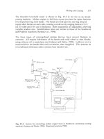
A worked example will be used to demonstrate external references. The procedure may
seem rather involved as it requires the user to save and open several drawings, but the
final result is well worth the effort. For the demonstration we will:
a) create a wblock
b) use the wblock as an xref to create two drawing layouts
c) modify the original wblock
d) view the two drawing layouts.
e) use the existing C:\BEGIN folder
Getting started
1 Open your A3PAPER standard drawing sheet and refer to Fig. 43.1.
2 Make a new current layer with:
name: XREF; colour: red; linetype: continuous.
3 Draw:
a) a circle of radius 18
b) a item of text, middled on the circle centre with height 5 and rotation angle 0. The
item of text is to be AutoCAD and is to be colour blue – fig. (a).
Creating the xref (a wblock)
1 At the command line enter WBLOCK <R> and:
prompt Write Block dialogue box
respond 1. Source: Objects
2. Base point: Pick point and pick circle centre point
3. Objects: Select objects, pick circle and text then right-click
4. Objects: Delete from drawing active
5. File name: XREFEX
6. Location: C:\BEGIN
7. Insert units: Millimeters
8. pick OK.
2 A preview of the wblock will be displayed and a blank screen returned, due to the delete
from drawing option being active.
Chapter 43
Beginning with AutoCAD 2002.qxd 14/06/2002 19:09 Page 301
Inserting the xref (drawing layout 1)
1 Menu bar with File-Close (no to save changes) then menu bar with File-Open and
select your A3PAPER standard sheet again with layer OUT current.
2 Menu bar with Insert-External Reference and:
prompt Select Reference File dialogue box (looks familiar?)
respond 1. scroll and pick C:\BEGIN
2. scroll and pick XREFEX
3. pick Open
prompt External Reference dialogue box
with Name: XREFEX and Path: C:\BEGIN\XREFEX.dwg
respond 1. ensure Reference Type: Attachment (black dot)
2. Retain path active
3. all on-screen options active, i.e. tick
4. dialogue box similar to Fig. 43.2
5. pick OK
prompt Attach Xref “XREFEX”: C:\BEGIN\XREFEX.dwg
and “XREFEX” loaded
then Specify insertion point and enter: 50,50 <R>
prompt Enter X scale and enter: 1 <R>
prompt Enter Y scale and enter: 1 <R>
prompt Specify rotation angle and enter: 0 <R>
3 The named external reference (XREFEX) will be displayed at the insertion point entered.
The complete process seems similar to inserting a wblock?
302 Beginning AutoCAD 2002
Figure 43.1 External reference example.
Beginning with AutoCAD 2002.qxd 14/06/2002 19:09 Page 302
4 Now rectangular array the inserted attached xref for:
a) 5 rows with row offset: 50
b) 6 columns with column offset: 60.
5 Save the layout as C:\BEGIN\XREFLAY1 – Fig. 43.1(c).
Inserting the xref (drawing layout 2)
1 Close the existing drawing then re-open A3PAPER
2 At the command line enter XREF <R> and:
prompt Xref Manager dialogue box
respond pick Attach
prompt Select Reference File dialogue box
respond 1. scroll and pick XREFEX from your C:\BEGIN folder
2. pick OK
prompt External Reference dialogue box
respond 1. Reference Type: Attachment
2. De-activate the three on-screen prompts (no tick)
3. Insertion point:- X: 200; Y: 250; Z: 0
4. X,Y,Z scales: 1
5. Rotation angle: 0
6. pick OK
3 Now polar array the inserted attached xref with:
a) centre point: 200,150
b) number of items: 11
c) angle to fill: 360
d) rotate items as copied active
4 Save the layout as C:\BEGIN\XREFLAY2 – Fig. 43.1(d).
External references 303
Figure 43.2 The External Reference dialogue box.
Beginning with AutoCAD 2002.qxd 14/06/2002 19:09 Page 303
Modifying the original xref
1 Close the current drawing.
2 Open the original XREFEX drawing from C:\BEGIN. This is the original wblock.
3 a) Change the text item to R2002 and colour green
b) Draw a hexagon, centred on the circle and circumscribed in a circle of radius 19.
Change the colour of this hexagon to blue. These modifications are shown in
Fig. 43.1(b).
4 Menu bar with File-Save to automatically update C:\BEGIN\XREFEX.
Viewing the original layouts
1 Close the existing drawing.
2 Menu bar with File-Open and:
a) pick XREFLAY1
b) note the Preview then pick Open
c) interesting result?
3 Menu bar with File-Open and:
a) pick XREFLAY2
b) note the Preview then pick Open
c) again an interesting result?
4 The layout drawings should display the modified XREFEX without any ‘help’ from us.
This is the power of external references. Surely this is a very useful (and dangerous
concept)?
5 Menu bar with Format-Layer and note the layer: XREFEX|XREF. This indicates that
an external reference (xrefex) has been attached to layer xref. The (|) is a pipe symbol
indicating an attached external reference.
6 This completes our simple investigation into xrefs.
Summary
1 External references are wblocks which can be attached to drawings
2 When the original xref wblock is altered, all drawing files which have the external
reference attached are automatically updated to include the modifications to the original
wblock.
304 Beginning AutoCAD 2002
Beginning with AutoCAD 2002.qxd 14/06/2002 19:09 Page 304
Isometric drawings
An isometric is a 2D representation of a 3D drawing and is useful as it can convey
additional information about a component which is not always apparent with the
traditional orthographic views. Although an isometric appears as a 3D drawing, the user
should never forget that it is a ‘flat 2D’ drawing without any ‘depth’.
Isometric drawings are created by the user with polar coordinates and AutoCAD has the
facility to display an isometric grid as a drawing aid.
Setting the isometric grid
There are two methods for setting the isometric grid these being by using a dialogue box
and via the keyboard.
Dialogue box method
1 From the menu bar select Tools-Drafting Settings and:
prompt Drafting Settings dialogue box
respond pick the Snap and Grid tab and:
1. Snap On(F9) active – black dot
2. Grid On(F7) active
3. Snap type & Style with:
a) Grid snap active
b) Isometric snap active
4. set Grid Y Spacing: 10
5. set Snap Y Spacing: 5
6. dialogue box as Fig. 44.1
7. pick OK.
Chapter 44
Figure 44.1 The Drafting Settings dialogue box.
Beginning with AutoCAD 2002.qxd 14/06/2002 19:09 Page 305
2 The screen will display an isometric grid of 10 spacing, with the on-screen cursor ‘aligned’
to this grid with a snap of 5.
3 Use the Drafting Settings dialogue box to ‘turn the isometric grid off’, i.e. pick the
Rectangular snap
4 The screen will display the standard grid pattern.
Keyboard entry method
1 At the command line enter SNAP <R> and:
prompt Specify snap spacing or [ON/OFF/Aspect/Rotate/Style/Type]
enter S <R> – the style option
prompt Enter snap grid style [Standard/Isometric]
enter I <R> – the isometric option
prompt Specify vertical spacing<5.00>
enter 10 <R>
2 The screen will again display the isometric grid pattern with the cursor ‘snapped to the
grid points’
3 Leave this isometric grid on the screen.
Isoplanes
1 AutoCAD uses three ‘planes’ called isoplanes when creating an isometric drawing, these
being named top, right and left. The three planes are designated by two of the X, Y and
Z axes as shown in Fig. 44.2(a) and are:
a) isoplane top: XY axes
b) isoplane right: XZ axes
c) isoplane left: YZ axes
2 When an isoplane is ‘set’ or ‘current’, the on-screen cursor is aligned to that isoplane
axis – Fig. 44.2(b).
3 The isoplane can be set by one of three methods:
a) at the command line enter ISOPLANE <R> and:
prompt Enter isometric plane setting[Left/Top/Right]
enter R <R> – right plane
b) Using a ‘toggle’ effect by:
1. holding down the Ctrl key (control)
2. pressing the E key
3. toggles to isoplane left
4. Ctrl E again – toggles to isoplane top
c) Using the F5 function key:
1. press F5 – toggles isoplane right
2. press F5 – toggles isoplane left, etc.
4 Note:
It is the users preference as to what method is used to set the isometric grid and isoplane,
but my recommendation is:
a) set the isometric grid ON from the Drafting Settings dialogue box with a grid spacing
of 10 and a snap spacing of 5
b) toggle to the required isoplane with Ctrl E or F5
c) isoplanes are necessary when creating ‘circles’ in an isometric ‘view’.
306 Beginning AutoCAD 2002
Beginning with AutoCAD 2002.qxd 14/06/2002 19:09 Page 306
Isometric circles
Circles in isometric are often called isocircles and are created using the ellipse command
and the correct isoplane MUST be set. Try the following exercise:
1 Set the isometric grid on with spacing of 10 and toggle to isoplane top.
2 Using the isometric grid as a guide and with the snap on, draw a cuboid shape as Fig.
44.2(c). The size of the shape is not important at this stage – only the basic shape.
3 Select the ELLIPSE icon from the Draw toolbar and:
prompt Specify axis endpoint or [Arc/Center/Isocircle]
enter I <R> – the isocircle option
prompt Specify center of isocircle
respond pick any point on top ‘surface’
prompt Specify radius of isocircle
respond drag and pick as required.
4 Toggle to isoplane right with Ctrl E.
5 At the command line enter ELLIPSE <R> and:
prompt Specify axis endpoint or [Arc/Center/Isocircle]
enter I <R>
prompt Specify center of isocircle and pick a point on ‘right side’
prompt Specify radius of isocircle and drag/pick to suit
6 Toggle to isoplane left, and draw an isocircle on the left side of the cuboid.
7 The cuboid now has an isometric circle on the three ‘sides’.
8 Now continue with the example which follows.
Isometric example
1 Open your A3PAPER standard sheet and refer to Fig. 44.3.
2 Set the isometric grid on, with a grid spacing of 10 and a snap spacing of 5.
3 With the LINE icon draw:
First point: pick towards lower centre of the screen
Next point and enter: @80<30 <R>
Next point and enter: @100<150 <R>
Next point and enter: @80<–150 <R>
Next point and enter: @100<–30 <R>
Next point and enter: @50<90 <R>
Next point and enter: @80<30 <R>
Next point and enter: @50<–90 <R><R> – fig. (a).
Isometric drawings 307
Figure 44.2 Three isometric concepts.
Beginning with AutoCAD 2002.qxd 14/06/2002 19:09 Page 307
4 With the COPY icon:
a) objects: pick lines D1, D2 and D3 then right-click
b) base point: pick intersection of pt 1
c) displacement: pick intersection of pt 2.
5 Draw the two lines (endpoint-endpoint) to complete the sides and top then draw a top
diagonal line – fig. (b).
6 Toggle to isoplane top.
7 With the ELLIPSE-Isocircle command:
a) pick midpoint of diagonal as the centre
b) enter a radius of 30.
8 Copy the isocircle:
a) from the diagonal midpoint
b) by: @50<90 – fig. (c).
9 Erase the diagonal.
10 Draw in the two ‘cylinder’ sides using the quadrant snap and picking the top and bottom
isometric circles.
11 Trim objects to these lines and erase unwanted objects to give the complete isometric
12 Task:
Draw two additional 30 radius isometric circles and modify to give the completed
isometric as fig. (d).
13 Save if required.
308 Beginning AutoCAD 2002
Figure 44.3 Isometric exercise.
Beginning with AutoCAD 2002.qxd 14/06/2002 19:09 Page 308
Summary
1 An isometric is a ‘flat’ 2D drawing having 3D visualisation.
2 An isometric grid is available as a drafting aid.
3 Isometrics are generally constructed with polar coordinates.
4 Circles are drawn with the ellipse-isocircle option and the correct isoplane must be set.
5 The objects snaps (endpoint, midpoint, etc.) are available with isometric drawings.
6 The modify commands (e.g. copy, trim, etc.) are available with isometrics.
7 The OFFSET command does not give the effect that the user would expect, and should
not be used.
8 The isocircle option of the ellipse command is only available when the isometric grid is
‘set on’. Try this for yourself with a normal rectangular grid.
Assignment
Activity 38: 6 into 1
This activity requires that isometric circles are drawn with the three isoplanes. The
recommended procedure is:
1 Draw an isometric cube of side 50.
2 Draw six isometric circles, one at the centre of each face. The radius is 25.
3 Copy each isometric circle by 50 at the appropriate angle, i.e. 30, 90, 150, –150, –90 and
–30.
4 Draw in the ‘cylinder sides’ using the quadrant snap.
5 Trim as required with care.
6 Erase unwanted objects.
7 The sectional isometric is left for you to complete.
Isometric drawings 309
Beginning with AutoCAD 2002.qxd 14/06/2002 19:09 Page 309
Model space and
paper space
AutoCAD has two drawing environments:
a) model space: used to draw the component
b) paper space: used to layout the drawing paper for plotting.
The two drawing environments are independent of each other and while the concept is
particularly applicable to 3D modelling we will demonstrate its use with a previously
saved 2D drawing.
Until now all work has been completed in model space.
Notes
1 The user must realise that this chapter is an introduction to the model/paper space
concept. Paper space is particularly targeted for plotting and as I have no idea what type
of plotter the reader has access to, I have assumed that no plotter is available. This does
not affect the exercise.
2 When the paper space environment is entered, a new icon will be displayed. The model
space and paper space icons are shown in Fig. 45.1.
3 Before paper space can be used, the paper space environment must be ‘entered’. This
can be achieved by:
a) picking MODEL from the status bar
b) picking one of the layout tabs from the drawing screen
c) entering TILEMODE then 0 at the command line.
Chapter 45
Figure 45.1 The model space and paper space icons.
Beginning with AutoCAD 2002.qxd 14/06/2002 19:09 Page 310
Getting started
1 Open your A3PAPER standard drawing sheet and:
a) Erase the rectangular border
b) Make two new layers, VP and SHEET both with your own colour selection and with
continuous linetype
c) Make layer VP current.
2 AutoCAD generally defaults with a Model tab, a Layout1 tab and a Layout2 tab. While
the layout tabs could be used for this exercise, we will create a new tab.
3 Menu bar with Tools-Wizards-Create Layout and:
prompt Create Layout – Begin dialogue box
respond alter Layout name to FACTORY then pick Next – Fig. 45.2
prompt Create Layout – Printer dialogue box
respond pick None then Next
prompt Create Layout – Paper Size dialogue box
respond 1. Drawing units: Millimeters
2. scroll at paper size and pick ISOA3 (420.00x297.00)
3. pick Next
prompt Create Layout – Orientation dialogue box
respond pick Landscape then Next
prompt Create Layout – Title Block dialogue box
respond pick None then Next
prompt Create Layout – Define Viewports dialogue box
respond 1. Viewport setup: Single
2. View scale: Scaled to Fit
3. pick Next
prompt Create Layout – Pick Location dialogue box
respond pick Select location
prompt Drawing screen returned
with Specify first corner at the command prompt
enter 10,10 <R>
prompt Specify opposite corner
enter 210,145 <R>
prompt Create Layout – Finish dialogue box
respond pick Finish.
Model space and paper space 311
Figure 45.2 The Create Layout (Begin) dialogue box.
Beginning with AutoCAD 2002.qxd 14/06/2002 19:09 Page 311
4 The drawing screen will be returned in Paper Space (note icon) with:
a) a white area – the A3 drawing paper
b) a dotted line area – the plottable area
c) a coloured rectangle – the created viewport
d) a new tab – FACTORY
e) the paper space icon displayed
f) PAPER is displayed in the Status bar.
5 As the paper space icon is displayed, the user is ‘in paper space’.
The sheet layout
Our A3 drawing paper has a paper space viewport and we now want to create another
three viewports. Refer to Fig. 45.3 and:
1 With layer VP current, menu bar with View-Viewports-1 Viewport and:
prompt Specify corner of viewport and enter: 230,75 <R>
prompt Specify opposite corner and enter: 380,170 <R>
2 Repeat the menu bar View-Viewports-1 Viewport selection and create another viewport
from 190,180 to 280,250
312 Beginning AutoCAD 2002
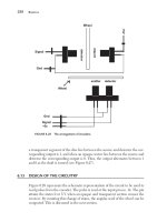
Figure 45.3 The LARGESC model/paper space exercise.
Beginning with AutoCAD 2002.qxd 14/06/2002 19:09 Page 312
3 Menu bar with View-Viewports-Polygonal Viewport and:
prompt Specify start point and enter: 50,160 <R>
prompt Specify next point and enter: @50<0 <R>
prompt Specify next point and enter: @50<72 <R>
prompt Specify next point and enter: @50<144 <R>
prompt Specify next point and enter: @50<–144 <R>
prompt Specify next point and enter: C <R>
4 We have now created three rectangular paper space viewports and one pentagonal paper
space viewport
The model
Rather than draw a new component we will insert an already completed and saved (I
hope) drawing into our created viewports. This drawing is the large scale factory layout
(LARGESC) from Chapter 38.
1 Enter model space with a left-click on PAPER in the Status bar.
2 The model space environment will be entered and the traditional model space icon will
be displayed in the rectangular viewports.
3 Make the first created viewport (lower left) active by:
a) moving the pointer into the rectangular area
b) left-click
c) cursor cross-hairs displayed and the viewport border appears highlighted.
4 Menu bar with Insert-Block and:
prompt Insert dialogue box
respond 1. pick Browse
2. scroll and pick C:\BEGIN folder
3. scroll and pick LARGESC (or your entered name)
4. pick Open
prompt Insert dialogue box with Name: LARGESC
respond 1. ensure Specify On-screen active, i.e. ticks
2. ensure Explode active, i.e. tick
3. pick OK
prompt Specify insertion point for block and enter: 0,0 <R>
prompt Specify scale factor for XYZ axes and enter: 1 <R>
prompt Specify rotation angle and enter: 0 <R>
5 Now select from the menu bar View-Zoom-All.
6 The active viewport will display the complete factory layout while the other three
viewports may display some lines.
7 Make each viewport active in turn by moving the pointing arrow into the viewport and
left-click, then View-Zoom-All from the menu bar and the layout will be displayed in
each viewport.
8 With the large rectangular viewport active:
a) erase all text
b) freeze layer DIMS.
9 Any text and dimensions ‘disappear’ from all the viewports.
Model space and paper space 313
Beginning with AutoCAD 2002.qxd 14/06/2002 19:09 Page 313
Using the viewports
1 With the lower right viewport active select View-Zoom-Window from the menu bar
and:
prompt Specify first corner and enter: 5000,1500 <R>
prompt Specify opposite corner and enter: 13000,8000 <R>
2 With the top right viewport active, zoom a window from 1000,1000 to 9000,8000
3 With the pentagonal viewport active, menu bar with View-Zoom-Scale and:
prompt Enter a scale factor
enter 0.015 <R>
4 Make layer TEXT current and the lower left viewport active and select from menu bar
Draw-Text-Single Line Text and:
prompt Specify start point of text and enter: 2500,2750 <R>
prompt Specify height and enter: 450 <R>
prompt Specify rotation angle and enter: 0 <R>
prompt Enter text and enter: AutoCAD R2002 <R>
5 The entered item of text will be displayed in all viewports.
6 Make layer OUT current with the lower right viewport active.
7 Draw two lines:
a) first point: 7250,5250 next point: 8750,5250
b) first point: 7250,6000 next point: @1500,0.
8 Use the TRIM command to trim these lines to give an opening into the factory – displayed
in all viewports. You may have to zoom in on the wall area to complete the trim, but
remember to zoom previous.
Using the paper space environment
1 Enter paper space with a left-click on MODEL in the status bar and try and erase any
object from a viewport – you cannot as they were created in model space.
2 Make layer TEXT current and add the following text items to the layout:
Start Ht Rot Text item
a) 10,4 4 0 Viewport 1: Complete factory layout
b) 230,60 4 0 Viewport 2: First enlarged view
c) 285,180 4 0 Viewport 3: Second enlarged view
d) 110,160 4 0 Viewport 4: Complete layout
e) 10,240 5 0 FOUR VIEWPORT FACTORY LAYOUT.
3 Now enter model space with a left-click on PAPER in the status bar and try to erase any
of the added text items – you cannot as they were created in paper space.
314 Beginning AutoCAD 2002
Beginning with AutoCAD 2002.qxd 14/06/2002 19:09 Page 314
Completing the layout
1 Enter paper pace and make layer SHEET current.
2 With the LINE command draw:
first point: 0,0 next point: @405,0 next point: @0,257
next point: @–405,0 next point: close.
3 Menu bar with Insert-Block and:
a) select Browse
b) pick your C:\BEGIN folder
c) scroll and pick TITLE then Open
d) activate Explode
e) insertion point: X 405; Y 0; Z 0
f) scale: uniform at 0.9
g) rotation: 0
h) pick OK.
4 The factory layout – created in paper space is now complete.
5 Task:
If you have access to a printer/plotter:
a) plot from model space with any viewport active
b) plot from paper space
c) in model space, investigate the coordinates of the top right corner of the left viewport
– about 22000,15000?
d) in paper space investigate the coordinates of:
1. top right corner of our sheet: 405,257?
2. top right corner of white area: 410,275?
e) Question: how can a drawing area on 22000,15000 be displayed on an A3 sheet of
paper? This is the ‘power’ of model/paper space.
Model/Paper space example 2
The previous exercise created the viewports prior to ‘inserting’ a drawing into the layout.
In this exercise, we will open a previously created drawing, and then adapt the paper
space layout.
1 Open WORKDRG (which has not been used for some time) and erase any text and
dimensions to leave the original red outline, two red circles and four green centre lines.
2 Make a new layer, named VP with continuous linetype, colour to suit and current.
3 Left-click on the Layout1 tab and:
prompt Page Setup – Layout1 dialogue box
with details about the Plotter to be used
respond pick Cancel – as I will assume no plotter.
4 The screen will be returned and display:
a) a paper space layout with the paper space icon
b) a white area – the drawing paper
c) a dotted area – the plottable area
d) a coloured outline – an active viewport
e) the WORKDRG and the black border within the coloured viewport.
5 Erase the coloured viewport and WORKDRG ‘disappears’.
6 Layer VP still current.
Model space and paper space 315
Beginning with AutoCAD 2002.qxd 14/06/2002 19:09 Page 315
7 Menu bar with View-Viewports-New Viewports and:
prompt Viewports dialogue box with two tabs:
a) New Viewports
b) Named Viewports
respond 1. New Viewports tab active
2. pick Three: Right
3. Viewport Spacing: 0.1
4. Setup: 2D – dialogue box as Fig. 45.4
5. pick OK
prompt Specify first corner and enter: 5,5 <R>
prompt Specify opposite corner and enter: 260,195 <R>
8 The drawing screen will be returned (in paper space) with a three viewport
configuration, each viewport displaying the WORKDRG and the black border.
9 Enter model space with one of the following methods:
a) pick PAPER from the Status bar
b) enter MS <R> at the command prompt
c) refer to Fig. 45.5.
10 Note the model space icon in all three viewports.
11 Make the lower left viewport active, and menu bar with View-Zoom-Extents.
12 a) Make the large right viewport active by moving the cursor into it and left-click
b) Erase the black border – it disappears from all viewports.
316 Beginning AutoCAD 2002
Figure 45.4 The Viewports dialogue box.
Beginning with AutoCAD 2002.qxd 14/06/2002 19:09 Page 316
13 a) Make the top left viewport active
b) Zoom-window from: 60,90 to 140,160
c) The circle and centre lines ‘fill the viewport’.
14 Still with the top left viewport active:
a) Make layer OUT current
b) Draw a circle with centre: 100,140 and radius: 3
c) Polar array this circle, about the large circle centre, for 13 items with 360 angle to fill
and rotated as copied.
15 Make the lower left viewport active and layer TEXT current.
16 Menu bar with Draw-Text-Single Line Text and:
a) start point: enter C <R> – the centre text option
b) centre point of text: 100,175
c) height: 5 and rotation angle: 0
d) text: AutoCAD <R>, then Release <R> then 2002 <R><R>
Model space and paper space 317
Figure 45.5 Model/Paper space exercise 2.
Beginning with AutoCAD 2002.qxd 14/06/2002 19:09 Page 317