Maya Secrets of the Pros Second Edition phần 6 ppt
Bạn đang xem bản rút gọn của tài liệu. Xem và tải ngay bản đầy đủ của tài liệu tại đây (1.23 MB, 31 trang )
the chances of that are slim, especially since not all the objects need the same number of
descriptors. Just saying no to underscores eliminates that issue. Besides, if you’re not putting
underscores in the attribute names, why not avoid them in the object names too and avoid
the headache? Trust me on this one!
The Golden Rules of a Successful Pipeline
Keeping a few rules in mind can make creating pipelines easier. Consistency, ease of use, flex-
ibility, and cleanliness are the four major rules to keep things running smoothly.
Consistency
Consistency is imperative. By creating guidelines and methods to follow you can create rou-
tines for every rig you make, as well as specify how things are done for the pipeline. If all
characters are brought in the exact same way, all tools that are based on that pipeline should
work the same. You want everyone to know that no matter what kind of rig they open, from
a cyber-octopus to a flying logo, the controls do the same thing—how the character is
brought into the scene, where to find controls and what they look like, how to switch from
HiRes to LoRes, and how to get the answers the rest of the pipeline needs. Consistency mini-
mizes error and makes the pipeline as a whole more efficient.
Using a naming guide is a good way to keep channels and functions the same from
character to character and will be less confusing for the animators. Once they use the flex
channel on an arm, they’ll remember what it did and how to best use it to their advantage
when they see the Flex attribute on a new character. I try to use the same terminology for all
channels. All IK/FK blend channels are named ikBlend, all constraint switches are named
switch, all eye controls are named eyeCntr, and so on. Beyond naming, the way things work
should be the same as well. If 0 is IK off, and 1 IK on, you don’t want to switch that between
characters; 0 should always be IK off. Similarly, all min max values should match, for exam-
ple, 0 to 1 or –10 to 10. To make this easy on myself, I create simple
for loop MEL scripts to
create attributes:
// add finger attrs to selected objects
// get the selected nodes
string $sel[] = `ls –sl`;
//loop through each of them
for ($each in $sel)
{
// add an attribute with min of -1 and max 1 that is keyable
addAttr –keyable 1 –min -1 –max 1 –ln “indexCurl” $each;
addAttr –keyable 1 –min -1 –max 1 –ln “midCurl” $each;
addAttr –keyable 1 –min -1 –max 1 –ln “ringCurl” $each;
addAttr –keyable 1 –min -1 –max 1 –ln “pinkyCurl” $each;
addAttr –keyable 1 –min -1 –max 1 –ln “thumbCurl” $each; }
//
Notice that I leave the side descriptor off the attribute name. This is so you can select mul-
tiple controls that have the same named attributes and change all of them simultaneously.
■ The Golden Rules of a Successful Pipeline 133
4345c05_p3.1.qxd 1/1/05 10:58 AM Page 133
To keep things consistent, I use curves to control everything that will have animation
applied to it. I create the same curves for the same kinds of controls. Even before an anima-
tor selects the object or checks its name, they have a good idea what that curve does. I use
curves because they don’t render and take up little memory to display. This allows the ani-
mator to quickly hide all the controlling objects for a playblast or review using the panel
view menu and turning off curves. Animators can also turn off everything but curves in the
selection mask, so they won’t accidentally select anything but animation controls. Using
geometry without shaders disconnected is a good idea, but it makes it harder to hide them
quickly and reveal them again, as well as discern selection. I use MEL to create these shapes
for me, to make life easier and less repetitive.
To create a simple curve control and attach it to a DAG (Directed Acyclic Graph) node,
follow these steps:
1. Using the CV or EP Curve tool, create your curve or curves as you normally would.
2. Show the curves’ CVs, and click the Snap to Point button to make a new curve, snap-
ping to its points.
3. On finishing the curve, Maya show the MEL script for creating that curve in the Script
Editor. Copy and paste that one line into an editor.
curve -d 3 -p -0.779152 0 -2.30167 -p 3.87703 ;
4. Add the -name flag to the MEL script to get the following:
curve –name “CNTRL” –d 3 –p 0 3.2 2 ;
Either use that as a sourceable entity on your shelf, or make it into a global proc.
To attach the curve to a controlling group, follow these steps:
1. Snap the curve to your group
2. Freeze its transformations.
3. Select the curves’ shape nodes by pick walking down once or by showing and selecting
Shape Nodes in the Outliner.
4. Shift+select the group, and use the following MEL to parent the shapes under the
transform:
//
parent –r –shape;
//
With this, you can create one transform node with any number of shape nodes, but
when you select using object mode, the DAG or transformation node is automatically
selected, not the curve shape or component level node. You can parent multiple shapes under
one transform to make elaborate control curves, but keeping it simple is always a good idea.
Too many shape nodes can slow down the Outliner tremendously when show shapes is
turned on (see Figure 5.6).
Employ the same consistency for hierarchies. The upper groups of a character should
always match. This can often become redundant for some characters, but it is better to have it
there for consistency. Groups take up little memory and add options for control, so the more
the merrier. I generally make a top group named
ALL and then parent under that two groups
COG and PARTS. The COG will generally have its pivot at the root or hip of the character and be
the top control for moving all the character.
PARTS will contain all the parts that cannot be
134 chapter 5 ■ The Character Pipeline
4345c05_p3.1.qxd 1/1/05 10:58 AM Page 134
moved or will cause double transformations, such as bound geometry. For the PARTS group, I
turn off the inherit transforms so the group doesn’t follow the parent. This keeps the charac-
ter condensed into one main group and keeps the Outliner and Hypergraph clean (see Fig-
ure 5.7).
Also be consistent in all pipeline scripts, plug-ins, and their storage areas. Keep all
scripts in a centrally located folder that everyone can access. They should all work similarly.
Mainly I use the same naming conventions for scripts, as most people do. I also use the same
name for the name of the script and the global procedure that must get called. For example,
a MEL script named
fixBarneyArmRt.mel would be run by calling fixBarnyArmRt in Maya. I
also tend to suffix MEL scripts that have a user interface or window with either
UI or Win.
The user automatically knows to expect a window to pop up when they run such a script.
Ease of Use
Making a pipeline easy to use is extremely important. The job of a rigger is to create an easy
way to control the character. In doing so, it should be readily apparent what each control
does and how to use the character. Don’t expect the animator to have read the same “how to
rig a character” book that you did, and to know that the spiral curve mover behind the char-
acter’s back is to control breathing. Name and place controls where they make sense. Again
keeping it simple is important. If there is better place to put a control or a better order for
channels in the Channel box, move them. You’re creating a new program or a new interface
■ The Golden Rules of a Successful Pipeline 135
Figure 5.6: Control shape Figure 5.7: A clean hierarchy
4345c05_p3.1.qxd 1/1/05 10:58 AM Page 135
for the character, so be sure it makes sense. The same should hold true for all the pipeline
scripts. The closer you can get to a one-button approach, the happier everyone will be.
Using the one-button approach means that the user need press or click only one shiny
button to run your script.
Flexibility
Flexibility is a one of the hardest things to achieve with a character pipeline. You want to
create a pipeline that can handle many possibilities. Luckily, since you’re creating the pipe-
line and guidelines to follow, you can ensure certain things—most important where to keep
and name scene files for geometry, rigs, animation files, and so on. You can take all the
known factors and hard-code them into your rules and scripts. Keeping things generic is also
a good general rule of thumb. Your import and animation transfer tools shouldn’t rely heav-
ily on naming and certain nodes, but rather on objects and animation, so they can work on
any type of rig. When creating scripts for automatically rigging characters, or autoRigs, I
tend to keep them as simple as possible and use them more like building blocks, rather than
complete rigs. For example, create an arm rig, a spine rig, and a foot rig that can be imple-
mented separately, rather than a “human” rig that has everything already put together and is
harder to repurpose for other characters. Just as it is hard to create any one rig that can do it
all, it is better not to limit yourself to an autoRig that cannot be interchangeable.
Cleanliness
Cleanliness is just a matter of keeping things organized. The cleaner, the easier. Delete unne-
cessary geometry and history. For geometry, my main rule of thumb is to delete all history
and freeze transformations. Brush nodes can be created by certain procedures that don’t
necessarily create Paint Effects, and they are not always automatically deleted from the
scene. These nodes can build up in the scene and make it heavy. Polygon tweaks can easily
become a mass of nodes that are unnecessary to the character rig, but can impede and cor-
rupt several deformers down the road; so clean ’em up! Turn off the Show DAG Objects
Only in the Outliner, and turn off show shape, hidden,
and underworld nodes in the Hypergraph to help you
see offending nodes and clean your scenes. Check con-
nections on unknown nodes before deleting, and name
the ones you want to keep. Watch for shape nodes,
those that are created and hidden when a deformer is
applied. These are known as Orig nodes and aren’t
necessarily deleted when history is deleted (see Fig-
ure 5.8). In most cases, you can just delete them.
When experimenting with a new technique or
rig, use a disposable file, and once you have the process
nailed, reopen an old scene and implement the changes
there. Using Undo doesn’t always get rid of everything
you created or the hidden nodes Maya creates for you.
Always prefix anything imported or referenced into a
136 chapter 5 ■ The Character Pipeline
Figure 5.8: Orig nodes
4345c05_p3.1.qxd 1/1/05 10:58 AM Page 136
scene. I use dummy prefixes when importing rig and geometry components into a scene so
that I can find the extra nodes brought in, such as shaders and sceneConfigurationsScript
nodes. That way I can find them using
select dummy_* and then check if they are necessary.
Beware using
optimize scene. This can delete empty sets that might be needed for your rigs
and script and delete unconnected shape nodes that might be needed down the pipeline. It’s
better to look for them by hand or to write your own clean-up scripts if you can.
The Rigging Curtain
To keep the technical side of things away from the creative, I employ what I call the “rigging
curtain”—basically all the things that go on behind the scenes that the creative side doesn’t
need to see. The rigging curtain is purposely hidden from the animators. If you find that the
animators are digging into the rigs and trying to find objects to move and ways to control
things that you didn’t intend them to animate, you might want to rethink they way your rig
works. Most animators will open a new rig and immediately use the Show All menu. Gener-
ally, I try to make everything that the animator doesn’t need completely inaccessible, by hid-
ing anything that is unnecessary. This includes IKhandles, lattices, clusters, joints, and almost
all deformers. To control the display of these items I generally put in a rig-specific control
that controls their display. Keep this control out of the keyable set so it doesn’t get animated.
If it is animated by accident, the animation on it should be discarded and not moved down
the pipeline.
Hide all rig specific geometry, such as wraps and blend targets. Hide and lock all unne-
cessary channels so they are not accidentally changed. Use import scripts to bring characters
into a scene and correctly name and place nodes. If necessary use
lockNode on objects you
think might get changed. No one should need to dig around in the folder
structure either; that’s behind the curtain too.
Defining a Character for the Pipeline
Let’s begin by talking a little about bringing a character into a scene. To
avoid name clashing and Maya’s automatic changing of names, I strongly
suggest you always use Resolve All Nodes when importing and or referenc-
ing with Use NameSpaces turned off. First, this configuration makes it easi-
er to find all the parts of a character. By using
(“select –r “barney_*”),
you can select all the nodes that came in with your imported/referenced
character. Name spaces make things slightly more difficult, in that some
MEL scripts treat the colon ( : ) as a special character so it can’t be used as
easily as an underscore. Second and more important, prefixes ensure that
no names in the scene clash, causing problems down the line. When refer-
encing multiple characters of the same name, rather than letting Maya add
suffix numbers to objects that clash, add a suffix to the prefix. For exam-
ple, the name barney, when referenced again, will have a prefix of bar-
ney1_. To help me do this automatically, I created a window that automati-
cally checks for characters in the scene with the current prefix and, if they
exist, adds a number to the prefix (see Figure 5.9).
To gain access to the relevant parts of your character once they are in
a scene, it’s best to develop an organization for them. A character template
■ Defining a Character for the Pipeline 137
Figure 5.9: A simple character
window
4345c05_p3.1.qxd 1/1/05 10:58 AM Page 137
or map that defines all the relevant parts of your char-
acter makes it possible to manage them. You’ll want to
access the high-resolution geometry, low-resolution
geometry, animation controls, and rigging components.
This makes it possible to select, delete, and get anima-
tion from a character quickly and easily in any scene.
This is especially important when importing rather than
referencing. In a referencing scene, all objects that are
referenced can be easily selected within Maya’s Refer-
ence Editor. When importing into a new scene, there is
no automatic way to keep track of those imported
objects. The most common ways to organize a charac-
ter are with Maya’s character sets, layers, and selection
sets (seen in Figure 5.10). Personally I prefer to work
with selection sets.
Character sets, although great to use with clips and Trax, tend to be intrusive and can
produce more overhead than needed. Numerous connections can slow things down quite a
bit, and since you can delete, cut, break, and in many other ways disconnect a channel from
its character, the danger of a broken pipeline is high. Re-creating the character tends not to
be a viable option once these connections are broken. Even though you can tell your anima-
tors not to delete animation through Break Connections in the Channel box, it can still hap-
pen easily.
Layers have similar issues to Maya’s character sets, in that they are easily accessible
and can be quickly changed at any time, breaking your pipeline. Another issue with layers is
that when an object is hidden by a layer, its visibility is overridden, but not displayed as such
in the Outliner or Hypergraph, making it difficult for the other teams to find all the geome-
try that needs to be visible. A bigger problem with layers is that they are exclusive, meaning
objects can be a part of one and only one layer, making it easy to accidentally remove objects
from layers if someone decides to create new layers with the same objects and again breaking
the pipeline. A character definition without layers frees up the layers for people to use with-
out fear of breaking the pipeline. My rule on layers in general is, don’t use them, and if you
do, delete them before sending your scene file down the pipeline.
I find selection sets the fastest, most flexible, and least intrusive option for character
organization. When using sets, you can hide individual objects or the entire set, and the layer
isn’t overriding the object visibility channel but changing it, so objects retain the color coding
that most Maya users are used to. You can temporarily hide objects and then easily display
them by showing the set. Unlike layers, objects can be in multiple sets. This makes it possible
to have lots of sets that contain the same objects, without intruding on normal work flow or
overriding any objects. Objects aren’t as easily removed and added to sets as layers. Even if
they are using sets, animators can create a new set without affecting the “pipeline” sets.
Last, sets can contain other sets. You can, therefore, make a hierarchy of organization.
I can break up all my character controls into separate sets, such as ARMRTset, ARMLFset,
and so on and then put those sets underneath one main set called ALLCNTRLSset. For key-
ing purposes, I can select just the arm controls or all the animation controls.
I name these sets with either all capital letters or in some way that delineates them from
the naming conventions for the rest of the sets. As mentioned, I generally make one set called
something like ALLCNTRLSset, make subsets for the arms, legs, and various other parts of
138 chapter 5 ■ The Character Pipeline
Figure 5.10: An example of
selection sets
4345c05_p3.1.qxd 1/1/05 10:58 AM Page 138
the character, and then make those sets part of the ALLCNTRLSset set
(see Figure 5.11).
To make it easier for riggers to deal with sets I added some tools to
the Outliner for creating, adding to, and removing objects from sets:
// create set
CreateQuickSelectSet;
Normally to create a quickSelectSet, you choose Create → Sets →
Quick Select Set, which isn’t such a bad thing, but by directly accessing
the command, you can speed up the process. To add and remove objects
and/or sets to sets, choose Window → Relationship Editors → Sets. To
speed that up, I wrote addToSet and removeFromSet scripts. You can
drag these to the shelf or make them into procedures and use them as
MEL scripts.
// select the object and then the set to add to
//AddToSet
string $sel[] = `ls -sl`;
for ($each in $sel)
{
sets -in $each $sel[0] ;
}
//
// select the object and then the set to remove from
//removeFromSet
string $sel[] = `ls -sl`;
for ($ech in $sel)
{
sets -rem $each $sel[0] ;
}
//
These tools will work with both
objects and sets; simply select the object and
then the set. Generally, I make a MEL script
to create these sets for me automatically.
That way I don’t have to do it by hand every
time, and it ensures consistency.
To control the visibility of animation
controls, I use an empty group and add
attributes to it that are connected to parts of
the character. I generally create Boolean
attributes for the left and right sides of the
arms and legs, as well as their IK and FK
controls, controls for the face, controls for
the fingers, and anything that might not always need to be visible in the scene (see Fig-
ure 5.12). I connect ikArmsLF to all the IK arm controllers for the left side of the character
■ Defining a Character for the Pipeline 139
Figure 5.11: Character definition sets
Figure 5.12: IK and FK arm controls
4345c05_p3.1.qxd 1/1/05 10:58 AM Page 139
and so on. These need to be connected to the actual controls themselves and shouldn’t hide
any geometry of the character. Although shape nodes don’t show it in the Channel box, their
visibility channel can be connected. If need be, you can connect to the visibility channel of
the actual shapes that show the control groups. You can do this with the Channel box or
with a MEL command. Remember, you can create a MEL command for any repetitive task;
this is one of those tasks.
I create a second empty group and use it to control all the deformers and rig compo-
nents in the same way. For example, I create ffd, clusters, ikHandles, or any types into chan-
nels to control the nodes I don’t want animators to see, but that I can still access easily for
myself and others (see Figure 5.13).
To create this control, I used the
text command to create curves and then parented all
the curves under one group called cntrls, using the process described earlier. I also have a
channel that is named and locked. This is purely for organization and readability. This is an
enum channel named _________ that I changed to rigCompone. I use blank attributes like
this all the time to make reading the Channel box easier.
As far as naming attributes, simple is the name of the game. Using the guides described
earlier, name channels with few characters, no spaces or underscores, and no redundancy.
There is no sense in naming a channel rightFingerBend when it’s on the handRTCntrl. This
approach is limiting in that you can’t combine the channels with other controls. If both the
handRTCntrl and the handLFCntrl the fingerBend channel, you can bend both fingers at the
same time, merely by selecting both controls and using the virtual slider from the Channel
box (select and MMB drag).
Also, you need not name character parts with the name of the character. Naming a
control barneyHandRtCntrl is going to be redundant once the character is brought into a
new scene. As discussed earlier, when importing or referencing a character into a new scene,
a prefix of the character name is added to all nodes. The name barneyHandRtCntrl becomes
barney_barneyHandRtCntrl. Just keep it simple and generic.
Because of the sets and the naming on import, it is easy to tell whether a character
already exists in the scene. By searching for
”*_ALLCNTRLS”, you can find all the characters in
the scene (
ls –name “_ALLCNTRLS“).
ls –name “*_ALLCNTRLS”
140 chapter 5 ■ The Character Pipeline
Figure 5.13: Visibility control
4345c05_p3.1.qxd 1/1/05 10:58 AM Page 140
From the selected objects, it’s just a matter of a simple loop statement using tokenize
or match to get the prefix and therefore the character’s name in the scene.
//
string $chars[] = `ls –name “*_ALLCNTRLS”’;
for ($each in $chars)
{
string $buffer[];
tokenize $each “_” $buffer;
print (“The characters name is “ + $buffer[0] + “\n”);
}
//
Creating a Ref Window
As I mentioned earlier, whether I am referencing or importing, I always turn off Resolve All
Nodes and Use NameSpaces. I prefer to keep Use NameSpacesoff because all the scripts I’ve
written are based on prefixes that contain underscores. Prefixing all nodes makes it possible
to grab all the parts of your character. In an import or reference pipeline, you can always use
a basic
select command to find all the relevant nodes. I use a reference window to ensure
that correct names are always used for the prefix, as well as to keep track if multiples of a
character are brought into the scene. Generally, I name the rig the name of the character, but
add a rig suffix. For example, the filename for barney is
barneyRig.ma. By using match or
tokenize I can get the base name of the file.
//
string $name = “barneyRig.mb”;
// search for the name prior to “R”
string $charName = `match”[^R]*” $name`;
print $charName;
//
Once you have the name of the character, you can use that as your prefix. The com-
mand for referencing, importing, and general filing of scenes is
file.
//
file -reference -type “mayaBinary” -rpr $charName $file ;
//
But, of course, before we get that far we should get the relevant files. We can use any
folder, so for this example I’ll use scenes. In the following code I’m getting the files in the
scenes folder that are named without the suffix
Rig.mb.
// get the current project and scenes directory
string $currentProject = `workspace -q -fn`;
// concatenate the current project with the scene dir
string $charFolder = ($currentProject + “/scenes/”);
string $characters[] = `getFileList -fld $charFolder -fs “*Rig.mb”`;
//
■ Creating a Ref Window 141
4345c05_p3.1.qxd 1/1/05 10:58 AM Page 141
Once you get the list, you can add it to your window. This, of course, depends on your
window. Let’s build a down-and-dirty GUI using
columnLayout and textScrollList.
//
global proc smimportWin ()
{
if (`window -exists smimportWin`)deleteUI smimportWin;
string $window = `window -w 200 -h 250 -title “smimportWin” -mxb 0
smimportWin`;
columnLayout;
string $scrollList = `textScrollList -h 250 -w 200 -
allowMultiSelection
false`;
button -l “import” -w 200 -c “smimportChar”;
setParent ;
showWindow $window;
}
//
Now we need to create a procedure to fill the textScrollList. Later we can embed
this into the window script.
//
// fill scroll list
string $currentProject = `workspace -q -fn`;
string $charFolder = ($currentProject + “/scenes/”);
string $characters[] = `getFileList -fld $charFolder -fs “*Rig.mb”`;
for ($eachChar in $characters)
{
// search for the name prior to “R”
string $charName = `match”[^R]*” $eachChar`;
print $charName;
textScrollList -e -append $charName $scrollList;
}
//
Now we need to create the procedure that will actually import the character.
//
//
global proc smimportChar ()
{
string $char[] = `textScrollList -q -si smimportWinScrollList`;
string $file = ($char[0] + “Rig.mb”);
// select all obects with _allCNTRLS
string $chars[] = `ls -ap “*_ALLCNTRLS”`;
string $prefix;
int $v;
int $i;
142 chapter 5 ■ The Character Pipeline
4345c05_p3.1.qxd 1/1/05 10:58 AM Page 142
if (`size $chars` >=1)
{
for ($each in $chars)
{
// use tokenize to get the base name
string $buffer[];
tokenize $each “_” $buffer;
// use match to get the basename without a number
string $name = `match “[^0-9]*” $buffer[0];
if ($name == $char[0])
{
$v++;
}
}
$prefix = ($char[0] + “_” + $v);
}
else
$prefix = $char[0];
file -reference -type mayaBinary -rpr $prefix $file;
}
//Done
When you call the window, the script the script automatically fills the window with the
available characters. By selecting a character and clicking the Import button, you can import
the character into the current scene with the proper naming and prefixes. New characters
with the same name will be prefixed with a number. I use
tokenize here to split the name of
the available characters based on the underscore. To use
tokenize, first create a string array
variable
$buffer[]. Then run the tokenize procedure using that variable to store the result-
ing information. The tokenize procedure takes the first argument, in this case the name of the
character, and then searches and splits that string using the second argument
“_”. It stores
what’s before and after each of the split strings into the third argument, in this case
buf-
fer[]
. The tokenize procedure returns only the integer number of items split. For example,
name_is_steve results in 3, putting name into buffer[0], is into $buffer[1], and steve into
$buffer[2]. To get the results of the first part of the string, or the character prefix, you want
$buffer[0]. I take the results of that and use match to strip off any numbers at the end of the
string. This code actually looks for all the characters that occur before any numbers. There-
fore,
super or super58 both result in super.
In an import pipeline, you can update characters by saving the animation, deleting the
character from the scene, reimporting the character, and then reattaching the animation. To
do this, you need a way to get that animation and transfer it. Obviously, you can move that
animation in a lot of ways. For this example and script, I’ll be using character sets and clips.
To create the character set, I simply select the *
_ALLCNTRLS set and then create the character
set. Since we’re using MEL and the set to create the character set, it will be created in the
same order every time, limiting the possibilities for nonmatching character sets. Once we cre-
ate the character set, it’s a simple matter to create a clip and export it to a scene file.
■ Creating a Ref Window 143
4345c05_p3.1.qxd 1/1/05 10:58 AM Page 143
To import the animation back in, create a character set again from the ALLCNTRLS set,
import the clip, and assign it. I then delete the character set and the clips, keeping the scene clean
but leveraging the power of clips and character sets. I’ve included two scripts for automatically
doing that. They are fairly simple, and you can easily change them to match your own produc-
tion pipeline:
smExportCharacterAnimation,mel and smImportCharacterAnimation.mel. To
use them, simply write the procedure in the Script Editor and add the name of the character.
SmExportCharacterAnimation barney;
SmImportCharacterAnimation barney;
Instead of typing the script, you can add a button to smImportWin and use the selected
character instead, just as in this script.
Expressions and Utility Nodes in Rigs
Using utility nodes in rigs can produce two major benefits, speed and reliability. Unlike
expressions, utility nodes don’t need the frame to change to update, don’t need to be parsed,
and each node as code serves one purpose. Consequently, a string of utility nodes calculates
much faster and without a change in time. Since a utility node is already binary code, Maya
doesn’t need to read it first and then parse it; it can be used immediately. Replacing all
expressions with utility nodes might not be practical or possible, but use them whenever you
can, and save expressions for mathematical equations that are too long or difficult to create
with nodes. Keeping the expression count low boosts the interactivity rate.
Since direct connections and not names connect utility nodes, you can change the
names of the connected nodes without fear of destroying their communication. Thus, they
are useful in import and reference pipelines. As discussed earlier, prefix all characters
brought into a new scene. However, renaming nodes when referencing or importing them
into a scene can cause any expressions that use MEL to fail. Basically, Maya renames nodes
based on the prefix selected inside an expression, but Maya won’t change names embedded
within MEL code that is inside the expression statement. For example, the following fails on
reference.
$ballTx = `getAttr ball.tx`;
ball.ty = $ballTx * 5;
The only name to be changed will be ball.ty that starts the second line. I try to con-
vert simple expressions such as these to utility nodes. In this example, I would connect
ball.tx to a multiplyDivide node’s input1X. Set the multiplyDivide node’s input2X to 0.5.
Then connect the multiplyDivide node’s output1D back to the
ball.ty (see Figure 5.14). It
may seem simple, but it can make a difference.
The basic math nodes in the Create Render Rode window are plusMinusAverage,
multiplyDivide, clamp, and setRange. Several other nodes that perform similar functions
such as addDoubleLinear and multDoubleLinear, do not appear in this window. As the
names state, these nodes add double linears, which refers to the type of channels used to con-
nect. A double linear is a float channel—any number including decimals. Double linears are
limited to connecting only two float values, but they are hidden by default in the Hypershade
window. Therefore, they can’t be accidentally deleted or used by your lighting department.
They are safer than renderNodes. Choosing Edit → Delete Unused Nodes will not affect
144 chapter 5 ■ The Character Pipeline
4345c05_p3.1.qxd 1/1/05 10:58 AM Page 144
these nodes, as they are not considered render nodes. To create these nodes, you use the MEL
createNode command.
//
createNode addDoubleLinear;
createNode multDoubleLinear;
//
You can use several other nodes for varying conditions; blendTwoAttr and pairBlend
are just two examples. You might have noticed some of the nodes Maya creates for you
when making connections, such as the unitConversion node. For a list of all the nodes in
Maya, you can check Maya Help, “Nodes and Attributes.”
Now let’s take a look at some examples using utility nodes. I created most of these con-
nections using the Connection Editor, but you can also do so using MEL. I’m in the habit of
creating these connections with small MEL procedures that I keep as simple connection tools
on my shelf.
When creating animated constraints by animating or connecting the “weights” of a
constraint, I use a reverse node (see Figure 5.15) to make the link between the two weights.
Add an attribute named blend to your control with Min and Max set to 0 to 1. Connect
blend to the w[0] of the constraint node, and then connect the w[0] to the input of a reverse
node. Connect the output of the reverse node to the w[1] of the constraint node. I find this
much easier, cleaner, and faster than creating a set driven key or an expression. In this
instance, you can’t use a multiplyDivide node with its input2X set to –1; the math would be
incorrect.
Rather than writing an
if/then statement, you can use conditions or even clamp
depending on your desired result. For this example, we’ll use clamp to make a square that
can tip up on its edges depending on the rotation of the control. Create a cube, and group it
to itself twice. In the front view, place the pivot of one group on the right corner of the
square, and name it rightGRP. Place the pivot of the other group on the left corner of the
square and name it leftGRP. Create a clamp node.
createNode clamp;
And finally create a curve for the control and name it cntrl.
■ Expressions and Utility Nodes in Rigs 145
Figure 5.14: A multiplyDivide example
4345c05_p3.1.qxd 1/1/05 10:58 AM Page 145
Connect the rotateZ of a cntrl to the clamp nodes inputR and inputG. We’ll use the R
channel as the right side connection and the G channel as the left side connection. Connect
the outputR to the rotateZ of the left group, and connect outputG to the rotateZ of the right
group. Set the clamp node’s minR to –1000 or more, and set maxG to 1000 or more. Now
when you rotate the cntrl in positive Z, the left group should rotate in Z, rotating the box off
that corner. That is, any number greater than 0 rotates the left group with the same number
as the cntrl. Now rotate the cntrl in negative Z. The leftGRP should now rotate the same
amount, lifting the box of its left corner. Even though the clamp has three channels (RGB) to
use we are only using two, and with different numbers. You’ll find that different nodes use
input RGB, input XYZ, and in some cases input2D[0] [2] [3] (see Figure 5.16). The best way
to check these inputs and outputs is by putting them in the Connection Editor and looking at
the possible connections.
Now let’s create a simple animation control for offset and speed using a single anima-
tion node, two multiplyDivide nodes, and one plusMinusAverage node. Follow these steps:
1. Create a NURBS sphere and name it ball.
2. Keyframe the ball at frames 0 and 10 with a translateY value of 0 and a keyFrame at
frame 5 a value of 1.
3. Turn off pre- and post-cycle for the animation.
146 chapter 5 ■ The Character Pipeline
Figure 5.15: Using the reverse utility node
Figure 5.16: Using the clamp utility node
4345c05_p3.1.qxd 1/1/05 10:58 AM Page 146
4. Add some attributes to ball named timeOffset, speed, and heightOffset.
5. Create the utility nodes—two multiplyDivide nodes and one plusMinusAverage node.
6. Graph the up and downstream connections for the ball in the Hypergraph.
7. To create the height offset control, connect the animation node, which should be called
ball_translateY to one of the multiplyDivide node’s input1X.
8. Connect the ball.heightOffset to the multiplyDivide’s input2X. Now this will multiply
the animation node’s output by whatever you choose. A value of 1 is the default.
Anything below or above that value causes the ball to bounce higher or lower.
To create the time and speed connections, connect the ball.timeOffset to the plus-
MinusAverage node’s input1D[0]. The input 1D is an array, so you need to use brackets to
delineate which object in the array you are connecting to. For the first connection, the Con-
nection Editor will allow you to do this, but for the consecutive connections, it is easiest to
do it with MEL. Now it’s time to connect the plusMinusAverage node’s input1D[1].
{
connectAttr time1.outTime plusMinusAverage1.input1D[1];
}
Time is directly connected to the Timeline. You can have only one time node, and it
has no connectable inputs. Now connect the plusMinusAverage’s output1D to the other
multiplyDivide’s input1X. Connect ball.speed to the multiplyDivide’s input2X. Finally, con-
nect the outputX of the multiplyDivide to the animation node’s input (see Figure 5.17).
{
connectAttr multiplyDivide1.outputX ball_translate.input;
}
Now you can change the ball bounce speed and offset the timing of it by changing the
ball.speed and the ball.timeOffset channels.
To make this exercise practical, duplicate the ball with Duplicate Input Graph on. This
not only duplicates the ball object, but the animation node and the utility nodes connecting
them. Time is connected to all since it cannot be duplicated. Now, by adjusting each ball’s
speed, heightOffset, and timeOffset channels, they can each have a different animation but
still be based on the same simple animation cycle.
You can then create a large number of bouncing balls just by duplicating the original
ball and randomizing each of their attributes. Of course, the easiest way to do this is with a
MEL script. I’ve included on the CD the MEL script
dupeball as an example. It duplicates
■ Expressions and Utility Nodes in Rigs 147
Figure 5.17: The offsetAnimation utility nodes
4345c05_p3.1.qxd 1/1/05 10:58 AM Page 147
the object with upstream on and randomizes the attributes on each, creating a random grid
of bouncing balls. Now, when you watch the animation, it appears as if all the balls have dif-
ferent animation and timings (see Figure 5.18).
Simple Tools You Should Be Using
Now let’s look at some scripts I wrote that make things simple when dealing with characters
and character setup.
You can use
smattrUp.mel and smattrDwn.mel to move user-created channels in the
Channel box. Ordinarily, you would have to open the Maya file in ASCII format and
reorder these attributes by hand or re-create them in the correct order. Using these scripts,
all you need do is select the attribute in the Channel box, and then run either
smattrUp or
smattrDwn. The attribute moves up or down in the list of channels. It won’t move the trans-
late rotate scale and visibility channels, as they are not permitted to move.
The script
HideLockChannel.mel basically hides and locks the selected channels in the
Channel box. When you hide a channel in the Channel box, you make it unkeyable.
Unkeyable attributes are not displayed in the Channel box.
By definition a channel is a keyable attribute.
148 chapter 5 ■ The Character Pipeline
Figure 5.18: Multiple animated objects
4345c05_p3.1.qxd 1/1/05 10:58 AM Page 148
The scripts ShowTranslate, showRotate, and showScale work on the selected objects.
As their names suggest they display or make keyable the translate, rotate, or scale of the cur-
rently selected objects.
I either put these scripts on my shelf or add them to my Channel box pop-up menu. To
do that, locate the
generateChannelMenu.mel script, and copy it to your local scripts folder.
You never want to overwrite an original Maya script; if you do, you might have to reinstall
to rebuild it. By copying the script to your scripts folder, it will get sourced last, and the pro-
cedure for that Maya session will be overwritten, rather than the MEL script itself. In your
copied script, simply find the generateChannelMenu procedure. Within that procedure, you
some lines similar to the following:
//
menuItem -l “Key Selected” -c “channelBoxCommand -key” keyItem;
menuItem -d true;
//
The menu -d true is the divider you see in your Channel menu. You can add your own
scripts simply by adding a new menu item and calling the script you want.
//
menuItem -divider true;
menuItem -l “upAttr” -c smattrUp;
menuItem -l “downAttr” -c smattrDown;
menuItem -l “hideLockAttr” -c hideLockChannel;
//
You can just as easily add to your Outliner menu the set scripts that were discussed by
editing
OutlinerEdMenu.mel.
In this chapter’s section on the CD, I am including MEL versions of the scripts dis-
cussed earlier in this chapter, although I recommend you learn how to write them on your
own. I hope that what I showed will at least put you on the right track.
Always Learning
I hope that this chapter has been helpful in the creation of your own pipelines and pipeline
tools, or at the very least give you some building blocks to start with. You can expand on
this information in a million ways. Nothing is set in stone, and you can accomplish any task
in many ways. Building a successful pipeline doesn’t happen overnight, and most likely your
pipelines will evolve with each successive production.
■ Always Learning 149
4345c05_p3.1.qxd 1/1/05 10:58 AM Page 149
CHAPTER
six
4345c06new_p3.1.qxd 1/1/05 11:00 AM Page 150
Hair Systems
Petre Gheorghian and Dariush Derakhshani
Hair systemsuse a collection of dynamic NURBS curves gen-
erated from hair follicles to simulate natural movement of long hair, hair
blowing in the wind, hair motion when a character is swimming underwa-
ter, and various hair styles (including braids and updos).
Although we’re talking about a sub-module of the Dynamics module
called Hair, you can put Hair dynamics to myriad uses beyond just hair. In
this chapter, we will jump into Hair dynamics with a few examples to take
a look at how to use them to create animations for scenes.
Each hair follicle contains one NURBS curve, but it can also contain a
number of hairs that make up a clump. The follicle has various attributes
for modifying the simulation as well as the appearance and style of the hair,
including a Braid attribute. The new Paint Hair tool allows for creating
and removing follicles as well as painting hair attributes (including Clump
Width Scale, Stiffness, and Braid).
But since Hair uses a generic dynamic curve simulation engine, you
can also use the curves to control IK chains, deformers, surfaces, and so on.
And we will continue to focus on that in the following examples. But first,
we’ll explain how Hair works.
4345c06new_p3.1.qxd 1/1/05 11:00 AM Page 151
Hair at a Quick Glance
Getting to know a few things about Hair will help build your foundation for the examples in
this chapter, as well as prepare you for some other dynamics exercises in Chapter 7.
You can create Hair on both NURBS and polygonal surfaces. But for polygons, UVs
should be nonoverlapping and fit between 0 and 1. Automatic mapping is a quick way to
achieve this, however. Before you create the Hair system, decide which renderer you will be
using because this affects the type of output you select.
You can create Hair in the form of NURBS curves (you use this option if you want to
use the Hair system for nonHair dynamic simulations), Paint Effects strokes, or both curves
and strokes. For example, you use Paint Effects strokes to create renderable hair for you
character, or you create NURBS curves to help you create animations for your scene.
Curve Types
There are three sets of curves for a given Hair system:
Start Position Curves This is the position of the hair at the start frame of a hair simu-
lation. At creation time, these curves stick out straight from the follicles on the surface
and show you the origin of your simulation.
Rest Position Curves This is the position of the hair when no forces are affecting it.
You can edit the shape of these curves to influence the look of the hair. You essentially
set these curves to give the hair curves a goal, if you will.
Current Position Curves These curves show you how the hair behaves when you play
the simulation.
To display any of these curves while you set up your simulation, choose Hair → Display.
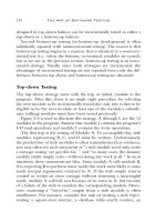
This is useful in showing how the hair is reacting to forces. Figure 6.1 shows you the Start
Position Curves as well as the Cur-
rent Position Curves as they fall
due to gravity.
You can easily edit the Start
and Rest Position curves by editing
their points in Component Mode
as you would any other CV or EP
curve. This way you can set your
simulation as you like it, to create,
for example, a simulation in which
you hair stands up when you grab
onto a power cable. Just don’t
mess with the Current Position
Curves; you want to let Maya run
those for you.
Do not edit the Current Position Curves. Doing so yields unpredictable results.
152 chapter 6 ■ Hair Systems
4345c06new_p3.1.qxd 1/1/05 11:00 AM Page 152
Passive Hair Curves
Passive curves interpolate the dynamic behavior of
active curves, but are less expensive than simulating
every curve. In the Create Hair options window, you
can specify a ratio of passive curves (Passive Fill) to
active curves to fill in hair without incurring a huge
simulation cost. Dynamic forces or collisions are not
computed on passive hairs, per se. Instead, they inter-
polate the motion of the active hairs in their own hair-
System node. Figure 6.2 shows passive curves in green
and active curves in blue.
The Simulation Method attribute on the follicle-
Shape node for a Hair system determines whether the
hair curve is dynamic, passive, or static, allowing you
to change the curve to suit your simulation. Static
hairs simply keep their start position and do not ani-
mate. That’s not fun.
Interacting with the Hair Simulation
What’s fun about hair if you can’t play with it? In the
following steps, you will learn how to interactively
■ Hair at a Quick Glance 153
Figure 6.1: The
Start and Current
Position Curves
Figure 6.2:
Passive and
Active curves
4345c06new_p3.1.qxd 1/1/05 11:00 AM Page 153
move, scale, or rotate the surface with hair while the simulation is playing and see the hair
update due to the dynamic forces applied to it.
Choose Hair → Display → Current Position to change the hair curves display to the
current dynamic curves, which are those that update when you play the simulation. This is
usually the default display so as not to cause confusion. To interact with your Maya object
while the simulation runs, follow these steps:
1. Of course, you’ll need a surface with hair. Create a NURBS sphere. While it is still
selected, choose Hair → Create Hair.
2. Select the surface with your hair. In the Dynamics menu set, choose Solvers → Interactive
Playback to play the hair simulation and allow you to interact with it at the same time.
3. Select the Move tool, and move the surface with hair while the simulation is running to
see how the hair reacts to the dynamic forces.
4. Now select the Scale or Rotate tool and act upon the surface with hair to see how the
hair reacts to the dynamic forces.
To tweak the hair simulation, adjust the Stiffness, Iterations, and even Gravity attributes
in the Dynamics section of the hairSystemShape node.
Hair Constraints
Choose Hair → Create Constraint, and then choose from a variety of options that are
designed to enhance specific hair looks. When you create a constraint, the constraint is set to
affect the selected hair curves. For example, three hair curves in Figure 6.3 have been given a
Rubber Band constraint. When you run the simulation, they are affected by the constraint’s
locator and its position and movement.
In component mode you select the curve components where you want to apply the con-
straining effect; you do not select the entire curve, unless you fear nothing.
To apply a constraint, first select the
hair curves and then apply the constraint
type you want. The Attribute Editor for the
hairConstraintShape node contains the
attributes that affect the way the constraint
interacts with the hair. For example, Glue
Strength rules the strength of the constraint,
and Stiffness lets you control the elasticity of
the constraint. If you want an effect in which
you are grabbing the ends of a few hairs
forcefully, Glue Strength is as high as Stiff-
ness. But if you are going for an effect in
which the static charge of a balloon rubbed
on some rabbit fur gently tugs on the ends
of the hair, both Glue Strength and Stiffness
are low.
154 chapter 6 ■ Hair Systems
Figure 6.3: Three
hairs are con-
strained by a
Rubber Band
constraint.
4345c06new_p3.1.qxd 1/1/05 11:00 AM Page 154
Using Hair Curves as Deformers
Now that you’ve seen a little bit of Maya Hair’s work-
ings, let’s look at a few examples of how Hair dynamics
can help run your animation. In this example, we are
creating the motion of an octopus’s tentacles with hair.
The Hair system curves will be made into wire
deformers and will drive the animation/deformation
of the octopus. Upon contact with the ground, the ten-
tacles will emit into a 2D fluid container positioned at
ground level to create a look of dust getting kicked up.
To begin, follow along with these steps:
1. Open the file
Octopus_start.mb. You should see
something like Figure 6.4.
2. Go to the top view. From the Create menu,
select the EP Curve tool.
3. Holding down the V key (for snap to point),
start clicking the tentacle’s axis following the
order shown at right.
4. Press Enter at the end of the tentacle (after the
ninth click) to create the curve. Smashing, isn’t it?
■ Using Hair Curves as Deformers 155
Figure 6.4: Fancy octopus
4345c06new_p3.1.qxd 1/1/05 11:00 AM Page 155
5. Change the scale on the Y axis to 0 for the curve you created to flatten it.
6. Go to the side view. Holding down the X key, move the curve up until it is in the center
of the tentacle. It needs to be positioned here to properly deform the surface.
If you go to the side view when you move with the curve snapping to the grid, it helps
because the octopus is 2 units above the ground and the curve will snap in the middle.
7. Choose Edit → Duplicate ❒. Set the Rotate Y value to 45, set the number of copies to
7, and click Duplicate. The next time you duplicate, be sure to reestablish these settings
unless you want eight more copies. The curves should be in the center of the tentacle.
8. Open the Outliner, select the eight curves, and then choose Hair → Make Selected
Curves Dynamic to turn the curve into a dynamic curve.
9. In the Outliner, click the plus sign beside hairSystem1Follicles to expand the view.
Shift+select all the hair follicles (from follicle1 to follicle8). You need to select the folli-
cle nodes themselves, instead of just selecting the group node.
10. In the Channel box, click inside the Point Lock field and choose Base from the drop-
down menu to lock down the now-dynamic curves at their base, which is at the start of
the curve.
11. In the Hair menu, choose Display → Current Position to ensure that you’re seeing the
curves as they move—not that we don’t trust you or anything.
12. In the Animation menu set, choose Deform and then select the Wire tool. This lets you
assign the curves as wire deformers.
13. Select the octopus geometry and press Enter to select the affected geometry. Now you
can select the deforming curves to be used.
14. In the Outliner, click the plus sign beside hairSystem1Out-
putCurves to expand its view as shown in Figure 6.5.
15. Shift+select all the output curves (from 9 to 16) and press
Enter. This creates wire deformers for these curves to drive
the deformation of the octopus. Again, it’s important to
select the output curves and not just the top node.
16. Select the octopus geometry, and then select hairSys-
tem1Follicles in the Outliner. In the Constrain menu,
choose Parent. This ensures that the follicles move with
the octopus’s body.
17. Expand hairSystem1OutputCurves in the Outliner. Select
the octopus geometry, Ctrl+select curve9BaseWire, and
choose Parent from the Constrain menu. Repeat this step
for all the other BaseWire curves found in hairSystem1Out-
putCurves. This step is important since it ensures that the base of the deformers moves
with the octopus geometry.
18. Set your playback end to 10000. This is to let you see the simulation run a good long
course. Plus big numbers are cool.
Now let’s see how the octopus body deforms while you move the geometry around in
the Perspective view. Select the octopus geometry, and in the Dynamics menu set, choose Sol-
vers → Interactive Playback. This plays the hair simulation while allowing you to interact
156 chapter 6 ■ Hair Systems
Figure 6.5: Expand the
Outliner view to select the
curves themselves.
4345c06new_p3.1.qxd 1/1/05 11:00 AM Page 156
with the octopus. Using the Move tool, select the octopus and move it while the simulation is
playing interactively.
Let’s add some collisions to the simulation and add some fluid emission for the fun of
it, so that the octopus kicks up a little dust:
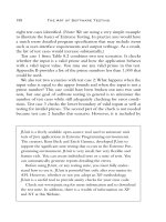
1. In the Outliner, select HairSystem1, and in the Attribute Editor, open the Collisions
section. Turn on Self Collide and Collide Ground to prevent the tentacles from going
through the ground plane or crossing each other.
2. From the Fluid Effects menu, choose Create 2D Container to add a 2D fluid container
to the simulation.
3. In the Channel box, set the Rotate X of the 2D fluid container to 90 and then move it
0.25 units on the Y axis to place it just above the ground plane, as shown in Figure 6.6.
4. Open the Attribute Editor for the fluid container. In the Contents Method section, set
Density to Static Grid, and set Velocity, Temperature, and Fuel to Off.
5. Open the Shading section of the Attribute Editor for the fluid container, and set the
color to dark gray for dust.
6. Open the Display section of the Attribute Editor for the fluid container, and set Boun-
dary Draw to None. This will just turn off the bounding box view of the fluid con-
tainer to clean up our view.
7. In the Outliner, select the fluid container, and then Ctrl+select the octopus geometry.
From the Fluid Effects menu, choose Add/Edit Contents → Emit from Object. This will
make the octopus emit inside the fluid container.
Now when you play back the simulation, dust will be emitted at the contact points
when the tentacles touch the ground, as you can see in Figure 6.7.
■ Using Hair Curves as Deformers 157
Figure 6.6: Posi-
tion the fluid
container to kick
up dust from
the octopus’s
movement.
4345c06new_p3.1.qxd 1/1/05 11:00 AM Page 157