Castings 2 Episode 6 ppt
Bạn đang xem bản rút gọn của tài liệu. Xem và tải ngay bản đầy đủ của tài liệu tại đây (853.52 KB, 25 trang )
The
mould
113
Gravity die casters that use sand cores (semi-
permanent moulds) will be all too aware of the
serious contamination of their moulds from the
condensation of volatiles from the breakdown of
resins in the cores. The build-up of these products
can be
so
severe as
to
cause the breakage of cores,
and the blocking of vents. Both lead to the scrapping
of castings. The blocking of vents
in
permanent
moulds is the factor that controls the length of a
production run prior to the mould being taken out
of service for cleaning. It is an advantage of sand
moulding that is usually overlooked.
the complete move, where possible, from lead-
containing alloys; or (iii) the use of chemical binders,
together with the total recycling of sand in-house.
This policy will contain the problem, and the
separation of metallic lead from the dry sand in the
recycling plant will provide a modest economic
resource.
There has been a suggestion that iron can
evaporate from the surface of a ferrous casting in
the form of iron carbonyl Fe(CO),. This suggestion
appears to have been eliminated on thermodynamic
grounds; Svoboda and Geiger
(1969)
show that the
compound is not stable at normal pressures at the
temperature of liquid iron. Similar arguments
eliminated the carbonyls of nickel, chromium and
molybdenum. These authors survey the existing
knowledge of the vapour pressures of the metal
hydroxides and various sub-oxides but find
conclusions difficult because the data is sketchy
and contradictory. Nevertheless they do produce
evidence that indicates vapour transport of iron and
manganese occurs by the formation of the sub-
oxides (FeO), and (MnO)z. The gradual transfer of
the metal by a vapour phase, and its possible
reduction back to the metal on arrival
on
the sand
grains coated in carbon, might explain some of the
features of metal penetration of the mould, which
is often observed to be delayed, and then occur
suddenly. More work is required to establish such
a mechanism.
The evaporation of manganese from the surface
of castings of manganese steel is an important factor
in the production of these castings. The surface
depletion of manganese seriously reduces the surface
properties of the steel. In a study of this problem,
Holtzer
(
1990)
found that the surface concentration
of manganese in the casting was depleted to a depth
of
8
mm and the concentration of manganese
silicates in the surface of the moulding sand was
increased.
Figure
1.9
confirms that the vapour pressure
of’
manganese is significant at the casting temperature
of steel. However, the depth of the depleted surface
layer is nearly an order of magnitude larger than
can be explained by diffusion alone. It seems
necessary to assume, therefore, that the transfer
occurs mainly while the steel is liquid, and that
some mixing of the steel is occurring in the vicinity
of the cooling surface.
It is interesting that a layer of zircon wash on
the surface of the mould reduces the manganese
loss by about half. This seems likely to be the result
of the thin zircon layer heating up rapidly, thereby
reducing the condensation of the vapour. In addition,
it will form a barrier to the progress of the manganese
vapour, keeping the concentration of vapour near
the equilibrium value close to the casting surface.
Both mechanisms will help to reduce the rate of
loss.
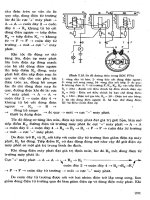
4.4.5
Mould
penetration
Levelink and Berg have investigated and described
conditions (Figure
4.15)
in which they claimed that
iron castings in greensand moulds were subject to
a problem that they suggested was a water explosion.
This led to a severe but highly localized form of
mould penetration by the metal.
n
Figure
4.15
Water hanimrr (mornenium
<ffec.i)
iect
picw,
(Levelink and Berg
1971).
However, careful evaluation of their work
indicates that it seems most likely that they were
observing a simple conservation of momentum
effect.
As
the liquid metal fills the last volume of
the mould it accelerates into the decreasing space,
with the result that high shock pressure is generated,
and sand penetration by the metal occurs. The effect
is similar to a cavitation damage event associated
with the collapse of bubbles against the ship’s
propeller. The oxides and bubbles that were present
in many of their tests seem to be the result of
entrainment in their rather poor filling system, and
not associated with any kind of explosion.
The impregnation of the mould with metal
in
last regions to till is commonly observed in all
metals in sand moulds.
A
pressure pulse generated
114
Castings
by the filling of a boss in the cope will often also
cause some penetration in the drag surface too.
The point discontinuity shown in Figure 2.27 will
be a likely site for metal penetration into the mould.
If the casting
is
thin-walled, the penetration on the
front face will also be mirrored on its back face.
Such surface defects in thin-walled aluminium alloy
castings in sand moulds are unpopular, because
the silvery surface of an aluminium alloy casting is
spoiled by these dark spots of adhering sand, and
thus will require the extra expense of blasting with
shot or grit
Levelink and Berg
(1968)
report that the problem
is increased in greensand by theuse of high-pressure
moulding. This may be the result of the general
rigidity of the mould accentuating the concentration
of momentum (weak moulds will yield more
generally, and thus dissipate the pressure over a
wider area). They list a number of ways in which
this problem can be reduced:
1.
Reduce mould moisture.
2. Reduce coal and organics.
3.
Improve permeability or local venting; gentle
filling of mould to reduce final filling shock.
4.
Retard moisture evaporation at critical locations
by local surface drying or the application
of
local oil spraying.
The reduction in the mechanical forces involved
by reduced pouring rates or by local venting are
understandable as reducing the final impact forces.
Similarly, the use of a local application of oil will
reduce permeability, causing the air to be
compressed, acting as a cushion to decelerate the
flow more gradually.
The other techniques in their list seem less clear
in their effects, and raise the concern that they may
possibly be counterproductive! It seems there is
plenty of scope for additional studies to clarify
these problems.
Work over a number of years at the University
of Alabama, Tuscaloosa (Lane
et
al.
1996),
has
clarified many of the issues relating to the
penetration of sand moulds by cast iron. Essentially,
this work concludes that hot spots in the casting,
corresponding to regions of isolated residual liquid,
are localized regions in which high pressures can
be generated by the expansion of graphite. The
pressure can be relieved by careful provision of
‘feed paths’ to allow the excess volume to be returned
to the feeder. The so-called ‘feed paths’ are, of
course, allowing residual liquid to escape, working
in reverse of normal feeding. If feed paths are not
provided, and if the hot spot region intersects the
metal/mould interface, then the pressure is relieved
by the residual melt forcing its way out to penetrate
the mould.
Naturally, any excess pressure inside the casting
will assist in the process of mould penetration. Thus
large steel castings are especially susceptible to
mould penetration because of the high metallostatic
pressure. This factor is in addition to the other
potential high-temperature reactions listed above.
This is the reason for the widespread adoption in
steel foundries
of
the complete coating of moulds
with a ceramic wash.
4.5
Metal surface reactions
Easily the most widely occurring and most important
metal/mould reaction is the reaction of the metal
with water vapour to produce a surface oxide and
hydrogen, as discussed in Chapter 1.
However, the importance of the release of
hydrogen and other gases at the surface of the metal,
leading to the possibility of porosity in the casting,
is to be dealt with in Chapter
6.
Here we shall
devote ourselves to the many remaining reactions.
Some are reviewed by Bates and Scott (1977). These
and others are listed briefly below.
4.5.1 Oxidation
Oxidation of the casting skin is common for low
carbon equivalent cast irons and for most low carbon
steels. It is likely that the majority of the oxidation
is the result
of
reaction with water vapour from the
mould, and not from air, which is expelled at an
early stage of mould filling as shown earlier. Carbon
additions to the mould help to reduce the problem.
The catastrophic oxidation of magnesium during
casting, leading to the casting (and mould) being
consumed by fire, is prevented by the addition of
so-called inhibitors to the mould. These include
sulphur, boric acid and other compounds such as
ammonium borofluoride. More recently, much use
has been made of the oxidation-inhibiting gas,
sulphur hexafluoride
(SF,),
which is used diluted
to about 2 per cent in air or other gas to prevent the
burning of magnesium during melting and casting.
However, since its identification as a powerful
ozone-depleting agent,
SF6
is being discontinued
for good environmental reasons.
A
return is being
made to dilute mixtures of
SO2
in
C02
and other
more environmentally friendly atmospheres are now
under development.
Titanium and its alloys are also highly reactive.
Despite being cast under vacuum into moulds of
highly stable ceramics such as zircon, alumina or
yttria, the metal reacts to reduce the oxides,
contaminating the surface of the casting with
oxygen, stabilizing the alpha-phase of the alloy.
The ‘alpha-case’ usually has to be removed by
chemical machining.
The
mould
I
IS
An addition of
5
or 6 per cent coal dust to the
mould further reduces it. The reaction seems to
start at about the freezing point of the eutectic,
about
1
150"C, and proceeds little further after the
casting has cooled to 1050°C (Rickards 1975)
(Figure 4.16).
4.5.2 Carburization
Mention has already been made of the problem of
casting titanium alloy castings
in
carbon-based
moulds. The carburization of the surface again
results in the stabilization
of
the alpha-phase, and
requires to be subsequently removed.
The difficulty is found with stainless steel of
carbon content less than
0.3
per cent cast in resin-
bonded (Croning) shell moulds (McGrath and
Fischer 1973). The carburization, of course, becomes
more severe the lower the carbon content of the
steel. Also, the problem is worse on drag than on
cope faces.
Carbon pick-up is the principal reason why low
carbon steel castings are not produced by the lost-
foam process. The atmosphere of styrene vapour,
which is created in the mould as the polystyrene
decomposes, causes the steel
to
absorb carbon (and
presumably hydrogen). The carbon-rich regions of
the casting are easily seen
on
an etched cross-section
as swathes of pearlite in an otherwise ferritic matrix.
In
controlled tests of the rate of carburization of
low carbon steel in hydrocarbon/nitrogen mixtures
at 925°C (Kaspersma and Shay 1982) methane was
the slowest and acetylene the fastest of the
carburizing agents tested, and hydrogen was found
to enhance the rate, possibly by reducing adsorbed
oxygen on the surface of the steel.
Section thickness
(rnm'")
0
10
20
4.5.3 Decarburization
At high ratios of H,/CH4, hydrogen decarburizes
steel at 925°C (Kaspersma and Shay 1982). This
may be the important reaction in the casting of
steel in greensand and resin-bonded sand moulds.
In the investment casting of steel, the
decarburization of the surface layer is particularly
affected because atmospheric oxygen persists in
the mould as a consequence of the inert character
of the mould, and its permeability to the surrounding
environment. Doremus and Loper (1970) have
measured the thickness of the decarburized layer
on a low carbon steel investment casting and find
that it increases mainly with mould temperature
and casting modulus. The placing of the mould
immediately after casting into a bin filled with
charcoal helps to recarburize the surface. However,
Doremus and Loper point out that there is a danger
that if the timing and extent of recarburization is
not correct, the decarburized layer will still exist
below!
In iron castings the decarburization of the surface
gives a layer free from graphite. This adversely
affects machinability, giving pronounced tool wear,
especially in large castings such as the bases of
machine tools. The decarburization seems to be
mainly the result of oxidation of the carbon by
water vapour since dry moulds reduce the problem.
0
50
100
200
300
400
Casting section thickness
(rnrn)
Figure
4.16
Depth
of
decarburization
in
grq iron plates
cast in greensand. Data from Rickards
(1975).
4.5.4 Sulphurization
The use of moulds bonded with furane resin
catalysed with sulphuric and/or sulphonic acid
causes problems for ferrous castings because of
the pick-up of sulphur in the surface of the casting.
This is especially serious for ductile iron castings,
because the graphite reverts from spheroidal back
to flake form in this high sulphur region. This has
a
serious impact
on
the fatigue resistance of the
casting.
4.5.5 Phosphorization
The use of moulds bonded with furane resin
catalysed with phosphoric acid leads
to
the
contamination of the surfaces of ferrous castings
with phosphorus. In grey iron the presence of the
hard phosphide phase in the surface causes
machining difficulties associated with rapid tool
wear.
116
Castings
4.5.6 Surface alloying
There has been some Russian (Fomin
et
al.
1965)
and Japanese (Uto and Yamasaki 1967) work on
the alloying of the surface of steel castings by the
provision of materials such as ferrochromium or
ferromanganese in the facing of the mould. Because
the alloyed layers that have been produced have
been
up
to 3 or
4
mm deep, it is clear once again
that not only is diffusion involved but also some
additional transport of added elements must be
taking place by mixing in the liquid state.
Omel’chenko further describes a technique to use
higher-melting-point alloying additions such as
titanium, molybdenum and tungsten, by the use of
exothermic mixes. Predictably enough, however,
there appear
to
be difficulties with the poor surface
finish and the presence of slag inclusions. Until
this difficult problem is solved, the technique does
not have much chance of attracting any widespread
interest.
4.5.7 Grain refinement
The use of cobalt aluminate (CoAl2O4) in the
primary mould coat for the grain refinement of
nickel and cobalt alloy investment castings is now
widespread. The mechanism of refinement is not
yet understood. It seems unlikely that the aluminate
as an oxide phase can wet and nucleate metallic
grains. The fact that the surface finish of grain-
refined castings is somewhat rougher than that of
similar castings without the grain refiner indicates
that some wetting action has occurred. This suggests
that the particles of CoA1,04 decompose to some
metallic form, possibly CoA1. This phase has a
melting point of 1628°C. It would therefore retain
its solid state at the casting temperatures of Ni-
based alloys. In addition it has an identical face-
centred-cubic crystal structure. On being wetted
by the liquid alloy it would constitute an excellent
substrate for the initiation of grains. The effect is
limited to a depth of about 1.25 mm in a Co-Cr
alloy casting (Watmough 1980) and is limited to
low casting temperatures (as is to be expected; there
can be no refinement if all the CoAl particles are
either melted or dissolved).
The addition of cobalt to a mould coat is also
reported to grain-refine malleable cast iron (Bryant
and Moore 197 l), presumably for a similar reason.
The use of zinc in a mould coat to achieve a
similar aim in iron castings must involve a quite
different mechanism, because the temperature of
liquid iron greatly exceeds not only the melting
point, but even the boiling point of zinc! It may be
that the action of the zinc boiling at the surface of
the solidifying casting may disrupt the formation
of the dendrites, detaching them from the surface
so
that they become freely floating nuclei within
the melt. Thus the grain refining mechanism in
this case is grain multiplication rather than
nucleation. The effect seems analogous to that
described in section 3.3.3.2 for acetylene black and
hexachlorethane coatings on moulds.
4.5.8 Miscellaneous
Boron has been picked up in the surfaces of stainless
steel castings from furane-bonded moulds that
contain boric acid as an accelerator (McGrath and
Fischer 1973).
Tellurium is sometimes deliberately added as a
mould wash to selected areas of a grey iron casting.
Tellurium is a strong carbide former, and will locally
convert the structure of the casting from grey to a
fully carbidic white iron. This action is said to be
taken to reduce local internal shrinkage problems,
although its role in this respect seems difficult to
understand. It has been suggested that a solid skin
is formed rapidly, equivalent to a thermal chill
(Vandenbos 1985). The effect needs to be used
with caution: tellurium and its fumes are toxic, and
the chilled region causes machining difficulties.
The effect of tellurium converting grey to white
irons is used to good purpose in the small cups
used for the thermal analysis
of
cast irons. Tellurium
is added as a wash on the inside of the cup. During
the pouring of the iron it seems to be well distributed
into the bulk
of
the sample, not just the surface,
so
that the whole test piece is converted from grey to
white iron. This simplifies the interpretation of the
cooling curve, allowing the composition of the iron
to be deduced.
Chapter
5
Solidification structure
In this chapter we consider how the metal changes
state from the liquid to the solid, and how the solid
develops its structure, together with its pore structure
due to the precipitation of gas.
In
a
later chapter we consider the problems
of
the usual volume deficit
on
solidification, and the
so-called shrinkage problems that lead to a different
set
of
void phenomena, sometimes appearing as
porosity.
This highlights the problem for the author. The
problem is how to organize the descriptions of the
complex but inter-related phenomena that occur
during the solidification
of
a casting. This book
could be organized
in
many different ways. For
instance, naturally, the gas and shrinkage
contributions to the overall pore structure are
complementary and additive.
The reader is requested to be vigilant to see this
integration.
I
am conscious that while spelling out
the
detail in a didactic dissection of phenomena,
emphasizing the separate physical mechanisms, the
holistic vision for the reader is easily lost.
5.1
Heat transfer
5.1.1
Resistances
to
heat transfer
The hot liquid metal takes time
to
lose its heat and
solidify. The rate at which it can lose heat is
controlled by
a
number of resistances described by
Flemings
(1974).
We shall follow his clear treatment
in
this section.
The resistances
to
heat flow from the interior of
the casting are:
1.
The liquid.
2.
The solidified metal.
3.
The metal/mould interface.
4.
The mould.
5.
The surroundings
of
the mould.
All these resistances add,
as
though
in
series.
as
shown schematically
in
Figure
5.1.
Random fluctuations
as
a
result
of
convection
I I
Mould Solid
Surroundings metal
Liquid
metal
As it happens, in nearly all cases
of
interest,
resistance
(I)
is negligible, as
a
result of bulk tlow
by forced convection during filling and thermal
convection during cooling. The turbulent flow and
mixing quickly transport heat and
so
smooth
out
temperature gradients. This happens quickly since
bulk flow
of
the liquid is fast, and the heat is
transported out
of
the centre of large ingots and
castings in a time that is short compared
to
that
required by the remaining resistances, whose rate
is controlled by diffusion.
I18
Castings
In many instances. resistance
(5)
is also negligible
in practice. For instance, for normal sand moulds
the environment
of
the mould does not affect
solidification, since the mould becomes hardly warm
on its outer surface by the time the casting has
solidified inside. However, there are, of course, a
number of exceptions to this general rule, all of
which relate to various kinds of thin-walled moulds,
which, because of the thinness of the mould shell,
are somewhat sensitive
to
their environment. Iron
castings made in Croning shell moulds (the Croning
shell process is one in which the sand grains are
coated with a thermosetting resin, which is cured
against a hot pattern to produce a thin, biscuit-like
mould) solidify faster when the shell is thicker, or
when the shell is thin and backed up with steel
shot. Conversely, the freezing of investment shell
castings in steel is delayed by a backing to the
shell of granular refractory material preheated to
high temperature, but is accelerated by being allowed
to radiate heat away freely to cool the surroundings.
Iron and steel dies for the casting of aluminium
alloys cool faster when the backs
of
the dies are
cooled by water.
Nevertheless, despite such useful ploys for
coaxing greater productivity, it remains essential
to understand that in general the major fundamental
resistances to heat flow from castings are items
(2),
(3)
and
(4).
For convenience we shall call these
resistances
1, 2
and
3.
The effects of all three simultaneously can
nowadays be simulated with varying degrees of
success by computer. However, the problem is both
physically and mathematically complex, especially
for castings of complex geometry.
There is therefore still much understanding and
useful guidance
to
be obtained by a less ambitious
approach, whereby we look at the effect of each
resistance in isolation, considering only one
dimension (i.e. unidirectional heat flow). In this
way we can define some valuable analytical solutions
that are surprisingly good approximations to casting
problems. We shall continue to follow the approach
by Flemings.
5.1.1.1 Resistance 1
:
The casting
It has to be admitted that this type of freezing regime
is not common for metal castings of high thermal
conductivity such as the light alloys or Cu-based
alloys.
However, it would nicely describe the casting
of Pb-Sb alloy into steel dies for the production of
battery grids and terminals; the casting of steel
into a copper mould; or the casting of hot wax into
metal dies as in the injection of wax patterns for
investment casting. It would be of wide application
in the plastics industry.
For the unidirectional flow of heat from a metal
poured exactly at its melting point
T,
against a
mould wall initially at temperature
To,
the transient
heat flow problem is described by the partial
differential equation, where
a,
is the thermal
diffusivity of the solid:
(5.1)
The boundary conditions are
x
=
0,
T
=
To;
at
x
=
S,
T
=
T,,,,
and at the solidification front the rate of
heat evolution must balance the rate of conduction
down the temperature gradient, Le.:
(5.2)
where
K,
is the thermal conductivity of the solid,
H
is the latent heat of solidification, and for which
the solution is:
s
=
2yKt
(5.3)
The reader is referred to Flemings for the rather
cumbersome relation for
y.
The important result
to
note is the parabolic time law for the thickening of
the solidified shell. This agrees well with
experimental observations. For instance, the
thickness
S
of
steel solidifying against a cast iron
ingot mould is found to be:
(5.4)
where the constants
a
and
b
are of the order of
3
and
25
respectively when the units are millimetres
and seconds. The result is seen in Figure
5.2.
The apparent delay in the beginning of
solidification shown by the appearance of the
constant
b
is a consequence of the following: (i)
the turbulence of the liquid during and after pouring,
resulting in the loss of superheat from the melt,
and
so
slowing the start of freezing, and
(ii)
the
finite interface resistance further slows the initial
rate of heat loss. Initially the solidification rate
will be linear, as described in the next section (and
hence giving the initial curve in Figure
5.2
because
of this plot using the square root of time). Later,
the resistance of the solidifying metal becomes
dominant, giving the parabolic relation (shown, of
course, as a straight line in Figure
5.2
because
of
the plot using the square root plot of time).
5.1.1.2
Resistance
2:
The metal/mould interface
In many important casting processes heat flow is
controlled to a significant extent by the resistance
at the metallmould interface. This occurs when both
the metal and the mould have reasonably good rates
of heat conductance, leaving the boundary between
the two the dominant resistance. The interface
Solidification structure
1
19
Time (min)
0
4 16 36 64
100
300
-g
200
E
-
D
c
._
n
-
8
v)
a,
Y
c
+
100
I
I
I
I
0
/'
2
4
6
8 10
/
G(rnin'/*)
/
Figure
5.2
Unidirectional solidification of pure iron
against
a
cast iron mould coated
vbsith
a
protective
wa.rh
(from Flemings
1974).
becomes overriding in this way when an insulating
mould coat is applied, or when the casting cools
and shrinks away from the mould (and the mould
heats up, expanding away from the metal), leaving
an air gap separating the two. These circumstances
are common in the die casting of light alloys.
For
unidirectional heat flow the rate of heat
released during solidification of a solid of density
ps
and latent heat of solidification
H
is simply:
(5.5)
This released heat has to be transferred to the mould.
The heat transfer coefficient
h
across the metal/
mould interface is simply defined as the rate of
transfer of energy
q
(usually measured in watts)
across unit area (usually a square metre) of the
interface, per unit temperature difference across
the interface. This definition can be written:
(5.6)
assuming the mould is sufficiently large and
conductive not to allow its temperature to increase
=
-
hA(T,,,
-
TO)
significantly above
To,
effectively giving a constant
temperature difference
(T,,
-
To)
across the interface.
Hence equating
5.5
and
5.6
and integrating from
S
=
0
at
t
=
0
gives:
(5.7)
It is immediately apparent that since shape is
assumed not to alter the heat transfer across the
interface, Equation
5.7
may be generalized for
simple-shaped castings to calculate the solidification
time
tf
in terms of the volume
V
to
cooling surface
areaA ratio (the geometrical modulus) of the casting:
P\
H
V
h(T,
-
T")
x
tf
=
All of the above calculations assume that
I7
is a
constant. As we shall see later, this is perhaps a
tolerable approximation in the case of gravity die
(permanent mould) casting of aluminium alloys
where an insulating die coat has been applied.
In
most other situations
h
is highly variable, and is
particularly dependent on the geometry of the
casting.
The
air
gap
As
the casting cools and the mould heats up, the
two remain in good thermal contact while the casting
interface is still liquid. When the casting starts
to
solidify, it rapidly gains strength, and can contract
away from the mould. In turn, as the mould surface
increases in temperature it will expand. Assuming
for a moment that this expansion is homogeneous,
we can estimate the size of the gap
d
as a function
of the diameter
D
of the casting:
where
a
is the coefficient of thermal expansion,
and subscripts c and m refer to the casting and
mould respectively. The temperatures
T
are
Tt
the
freezing point,
Tmi
the mould interface. and
To
the
original mould temperature.
The benefit
of
the gap equation is that it shows
how straightforward the process of gap formation
is. It is simply a thermal contraction-expansion
problem, directly related to interfacial temperature.
It indicates that for a casting a metre across which
is allowed
to
cool to room temperature the gap
would be expected to be of the order of
10
mm at
each of the opposite sides. This is a substantial gap
by any standards!
Despite the usefulness
of
the elementary formula
in giving some order-of-magnitude guidance
on
the dimensions of the gap, there are a number of
interesting reasons why this simple approach
requires further sophistication.
120
Castings
In a thin-walled aluminium alloy casting
of
section only 2 mm the room temperature gap would
be only
10
pm. This is only one-twentieth of the
size of an average sand grain
of
200 pm diameter.
Thus the imagination has some problem in
visualizing such a small gap threading its way amid
the jumble
of
boulders masquerading as sand grains.
It really is not clear whether it makes sense to talk
about a gap in this situation.
Woodbury and co-workers (2000) lend support
to this view for thin wall castings. In horizontally
sand cast aluminium alloy plates of
300
mm square
and up to 25 mm thickness, they measured the rate
of transfer
of
heat across the metal/mould interface.
They confirmed that there appeared to be no
evidence for an air gap. Our equation would have
predicted a gap of 2.5 pm. This small distance could
easily be closed by the slight inflation of the casting
because of two factors: (i) the internal metallostatic
pressure provided by the filling system (no feeders
were used), and (ii) the precipitation of a small
amount of gas; for instance, it can be quickly shown
that
1
per cent porosity would increase the thickness
of the plate by at least
70
pm. Thus the plate would
swell by creep under the combined internal pressure
due to head height and the growth
of
gas pores
with minimal difficulty. The 25 pm movement from
thermal contraction would be
so
comfortably
overwhelmed that a gap would probably never have
chance to form.
Our simple air gap formula assumes that the
mould expands homogeneously. This may be a
reasonable assumption for the surface of a greensand
mould, which will expand into its surrounding cool
bulk material with little resistance. A rigid,
chemically bonded sand will be subject to more
restraint, thus preventing the surface from expanding
so
freely. The surface of a metal die will, of course,
be most constrained of all by the surrounding metal
at lower temperature, but the higher conductivity
of the mould will raise the temperature of the whole
die more uniformly, giving a better approximation
once again to homogeneous expansion.
Also, the sign of the mould movement for the
second half of the equation is only positive if the
mould wall is allowed to move outwards because
of small mould restraint (i.e. a weak moulding
material) or because the interface is concave.
A
rigid mould and/or a convex interface will tend to
cause inward expansion, reducing the gap, as shown
in Figure 5.3. It might be expected that a flat interface
will often be unstable, buckling either way. However,
Ling and co-workers (2000) found that both theory
and experiment agreed that the walls of their cube-
like mould poured with white cast iron distorted
outwards in the case
of
greensand moulds, but
inwards in the case
of
the more rigid chemically
bonded moulds.
There are further powerful geometrical effects
Figure
5.3
Movement
of
mould walls, illustrating the
principle
of
inward expansion in convex regions and
outward expansion in concave regions.
to
upset our simple linear temperature relation.
Figure 5.4 shows the effect of linear contraction
during the cooling of a shaped casting. Clearly,
anything in the way
of
the contraction of the straight
lengths of the casting will cause the obstruction
to
be forced hard against the mould. This happens in
the corners at the ends of the straight sections.
Gaps cannot form here. Similarly, gaps will not
occur around cores that are surrounded with metal,
and on to which the metal contracts during cooling.
Conversely, large gaps open up elsewhere. The
situation in shaped castings is complicated and is
only just being tackled with some degree of success
by computer models.
Figure
5.4
Variable air gap in a shaped casting: arrows
denote the probable sires
of
zero gap.
Solidification
mucturc
I2
I
Richmond and Tien (1971) and Tien and
Richmond (1982) demonstrate via
a
theoretical
model how the formation of the gap is influenced
by the internal hydrostatic pressure
in
the casting,
and by the internal stresses that occur within the
solidifying solid shell. In Richmond
et
al.
(1990)
Richmond goes on to develop his model further,
showing that the development of the air gap is
not
uniform. but is patchy. He found that air gaps were
found to nucleate adjacent
to
regions of the solidified
shell that were thin, because,
as a
result of stresses
within the solidifying shell, the casting/mould
interface pressure first dropped to zero at these
points. Conversely. the casting/mould interface
pressure was found to be raised under thicker regions
of the solid shell, thereby enhancing the initial non-
uniformity in the thickness of the solidifying shell.
Growth becomes unstable, automatically moving
away from uniform thickening. This rather counter-
intuitive result may help
to
explain the large growth
perturbations that are seen from time to time in the
growth fronts of solidifying metals. Richmond
reviews
a
considerable amount of experimental
evidence
to
support this model. All the experimental
data seem to relate to solidification in metal moulds.
It
is possible that the effect is less severe
in
sand
moulds.
Attempts to measure the gap formation directly
(Isaac
et
ul.
1985; Majumdar and Raychaudhuri
198
1)
are extremely difficult to carry out accurately.
Results averaged for aluminium cast into cast iron
dies of various thickness reveal the early formation
of the gap at the corners of the die where cooling
is fastest. and the subsequent spread of the gap to
the centre of the die face.
A
surprising result is the
reduction of the gap if thick mould coats are applied.
(The results in Figure
5.5
are plotted
as
straight
lines. The apparent kinks in the early opening of
the gap reported by these authors may be artefacts
of their experimental method.)
It is not easy to see how the gap can be affected
by the thickness of the coating. The effect may be
the result of the creep of the solid shell under the
internal hydrostatic pressure of the feeder. This is
more likely to be favoured
by
thicker mould coats
as
a
result of the increased time available and the
increased temperature of the solidified skin of the
casting. If this is true then the effect is important
because the hydrostatic head in these experiments
was modest, only about 200mm. Thus for
aluminium alloys that solidify with higher heads
and times as long or longer than a minute or
so,
this mechanism for gap reduction will predominate.
It
seems possible, therefore, that in gravity die
casting of aluminium the die coating will have the
major influence on heat transfer, giving a large and
stable resistance across the interface. The air gap
will be
a
small and variable contributor. For
computational purposes, therefore, it is attractive
Corner
0
Centre
r7
Time
(s)
Figure
5.5
Results civeraged from varioii.c die.%
(ISLI~K
('1
al.
1985).
illustrating the .start
of
the air gap ut
the
corners, and its spread to the centre ofthe inoiild
,film.
Increased thickness
of
mould coating is
.seen
to
delq
solidification and
to
reduce the growth
of'the
gap.
to
consider the great simplification of neglecting
the air gap in the special case of gravity die casting
of aluminium.
In conclusion, it is worth mentioning that the
name 'air gap' is perhaps
a
misnomer. The gap will
contain almost everything except air. As we have
seen previously, mould gases are often high
in
hydrogen, containing typically
50
per cent. At room
temperature the thermal conductivity of hydrogen
is approximately 6.9 times higher than that of air,
and at 500°C the ratio rises to 7.7. Thus, the
conductivity of
a
gap at the casting/mould interface
containing a
5050
mixture of air and hydrogen at
500°C
can be estimated to be approximately a factor
of
4
higher than that of air. In the past, therefore,
most investigators in this field have probably chosen
the wrong value for the conductivity of the gap,
and by a substantial margin!
The heat-transfer coefficient
The authors
Ho
and Pehlke (1984) from the
University of Michigan have reviewed and
researched this area thoroughly. We shall rely mainly
on their work in this section.
When the metal first enters the mould the
macroscopic contact is good because of the
conformance of the molten metal. Gaps exist
on
a
microscale between high spots
as
shown in Figure
5.6.
At the high spots themselves, the high initial
heat
flux
causes nucleation of the metal by local
severe undercooling (Prates and Biloni 1972). The
solid then spreads to cover most of the surface
of
the casting. Conformance and overall contact
between the surfaces
is
expected to remain good
during all of this early period, even though the
122
Castings
produce analytical equations for each of these
contributors to the total heat flux. We can summarize
their findings as follows:
(b)
Figure
5.6
MetaWmould interface at an early stage when
solid is nucleating
at
points
of
good thermal contact.
Overall macroscopic contact
is
good at this stage (a).
Later (bj the casting gains strength, and casting and
mould both deform, reducing contact to isolated points at
greater separations
on
non-conforming rigid surfaces.
mould will now be starting to move rapidly because
of distortion.
After the creation of a solidified layer with
sufficient strength, further movements of both the
casting and the mould are likely to cause the good
fit to be broken,
so
that contact is maintained across
only a few widely spaced random high spots (Figure
5.6b).
The total transfer of heat across the interface
may be written as the sum of three components:
h,
=
h,
+
h,
+
h,
where
h,
is
the conduction through the solid contacts,
h,
is the conduction through the gas phase, and
h,
is that transferred by radiation.
Ho
and Pehlke
Table
5.1
Mould and metal constants
While the casting surface can conform, the
contribution of solid-solid conduction is the most
important. In fact, if the area of contact is
enhanced by the application of pressure, then
values of
h,
up to
60
000
Wm-2K-' are found
for aluminium in squeeze casting. Such high
values are quickly lost as the solid thickens and
conformance is reduced, the values fallin to
more normal levels of
100-1000
Wm-
K
(Figure
5.7).
When the interface gap starts to open, the
conduction through solid contacts becomes
negligible. The point at which this happens is
clear in Figure 5.7b. (The actual surface
temperature of the casting and the chill in this
figure are reproduced from the results calculated
by
Ho
and Pehlke.) The rapid fall of the casting
surface temperature is suddenly halted, and
reheating of the surface starts to occur. An
interesting mirror image behaviour can be noted
in the surface temperature of the chill, which,
now out of contact with the casting, starts to
cool. The estimates of heat transfer are seen to
simultaneously reduce from over
1000
to around
100
Wm-*K-' (Figure 5.7~).
8
-1
J.
After solid conduction diminishes, the important
mechanism for heat transfer becomes the
conduction of heat through the gas phase. This
is calculated from:
h,
=
Wd
where
k
is
the thermal conductivity of the gas and
d
is the thickness of the gap. An additional correction
is noted by
Ho
and Pehlke for the case where the
Material Melting Liquid- Specific heat Densiy Thermal conductivity
point solid
(J.Kg
K)
(kglm
1
(Jlrn
K
s)
("C)
contraction
(%I
Solid Liquid Solid Liquid Solid Liquid
20°C
m.p. m.p
20°C
m.p. m.p.
20°C
m.p. m.p.
Pb 327 3.22
130
(138) 152
11680 11020 10678 39.4 (29.4) 15.4
Zn
420 4.08
394
(443) 481
7140 (6843) 6575 119 95 9.5
Mg 650
4.2 1038 (1300) 1360
1740
(1657)
1590 155
(90)? 78
A1
660 7.14 917 (1200)
1080 2700 (2550) 2385 238
-
94
cu
1084 5.30
386
(480) 495
8960 8382
8000 397
(235) 166
Fe 1536 3.16 456 (1130) 795 7870
7265 7015
73 14)?
-
Graphite
- -
1515
-
-
2200
-
-
147
Silica
sand
-
1130
-
1500
- -
0.0061
-
(Mullite) 750
-
-
1600
- -
0.0038
- -
- -
Investment
- -
Plaster
-
840
- -
1100
-
0.0035
-
-
References:
Wray
(1976); Brandes
(1
99
I
);
Fleming5
(1
974)
Solidification structure
I23
Transducers
nn
Water
cooling
coils
Copper
chill
AI
casting
127 rnm
0
(a)
$
400
300
E
200
F
100 TC 1
0
5
10
15
2025
Time
(rnin)
(b)
E
2500
._
$
2000
t
E“
1000
1500
m3
-
500
c
0
m
I
c
0
5
10
15
2025
Time (min)
(c)
Figure
5.7
Results
,froin
Ho
and Pehlke
(I
984)
iUiisirating
the
femperurure
histor!
ticross
a
casririg/chill
intrrftrcr,
arid
the
inferred
heat
tramfer
co@cirnt.
becomes of increasing importance to heat transfer
at these higher temperatures.
5.1.1.3 Resistance
3:
The mould
The rate of freezing of castings made in silica sand
moulds is generally controlled by the rate at which
heat can he absorbed by the mould. In fact, compared
to many other casting processes, the sand mould
acts
as
an excellent insulator, keeping the casting
warm. However, of course, ceramic investment and
plaster moulds are even more insulating, avoiding
premature cooling of the metal, and aiding fluidity
to
give the excellent ability
to
fill thin sections for
which these casting processes are renowned. It is
regrettable that the extremely slow cooling can
contribute to rather poorer mechanical properties.
Considering the simplest case
of
unidirectional
conditions once again, and metal poured at its
melting point
T,
against an infinite mould originally
at temperature
To,
but whose surface is suddenly
heated
to
temperature
T,
at
I
=
0,
and that has
thermal diffusivity
a,,,
we now have:
d2T
-
=a,-
dT
at
ax2
Following Flemings, the final solution is:
(5.9)
gap is smaller than the mean free path of the gas
molecules, which effectively reduces the
conductivity. Thus heat transfer now becomes a
strong function of gap thickness. As we have noted
above, it will also be a strong function of the
composition of the gas. Even a small component
of hydrogen will greatly increase the conductivity.
For the case of light alloys, Ho and Pehlke find
that the contribution to heat transfer from radiation
is of the order of
1
per cent of that due to conduction
by gas.
Thus
radiation can he safely neglected at
these temperatures.
Heat transfer coefficients have been calculated
by Hallam
et
a/.
(2000)
for the case of A1 alloy
gravity die (permanent mould) castings. They
demonstrate excellent predictions based on the
assumption that the resistance of the die coating is
mainly due to the gas voids between the casting
and the coating surface. Thus the character of the
coating surface was a highly influential factor in
determining the heat transfer across the casting/
mould interface.
For higher-temperature metals, results by Jacobi
(
1976)
from experiments on the casting of steels in
different gases and
in
vacuum indicate that radiation
This relation is most accurate for the highly
conducting non-ferrous metals aluminium,
magnesium and copper. It is less good for iron and
steel, particularly those ferrous alloys that solidify
to the austenitic (face-centred cubic) structure that
has especially poor conductivity.
Note that at
a
high temperature heat is lost more
quickly,
so
that
a
casting in steel should solidify
faster than a similar casting in grey iron. This perhaps
surprising conclusion is confirmed experimentally,
as seen in Figure
5.8.
Low heat of fusion of the metal,
H.
similarly
favours rapid freezing because less heat has to be
removed. Therefore despite their similar freezing
points, magnesium castings freeze faster than similar
castings in aluminium.
The product
K,p,C,
is
a useful parameter
to
assess the rate at which various moulding materials
can absorb heat. The reader needs to be aware that
some authorities have called this the heat diffusivity,
and this definition was followed
in
Castings
(Campbell 199
1).
However, originally the
definition of heat diffusivity
h
was
(K,,p,C,)”’
as
described for instance by Ruddle (1950).
In
subsequent years the square root seems to have
124 Castings
1
05
104
c
c
V
c
E
-
P
2
103
c
F
102
10'
103
1
o2
IC
I
1
100
/
/
/
/
100
AI-8Si gravity die
AI-8Si squeeze cast
Steel in steel
mould
(Heine,
1984)
10
100
Oo0
Figure
5.8
Freezing times
of
plate-shaped
Modulus
(rnrn)
castings in different
alloys
and moulds.
been overlooked in error. Ruddle's definition is
therefore accepted and followed here. However, of
course, both
b
and
6'
are useful quantitative
measures. What we call them is merely a matter of
definition.
(I
am grateful to John Berry of Mississippi
State University for pointing out this fact.
As
a
further aside from Professor Berry, the units of
b
are even more curious than the units of toughness;
see Table
5.2.)
For simple shapes, if we assume that we may
replace
S
with
VJA
where
V,
is the volume solidified
at a time
t,
and
A
is the area of the metal/mould
Table
5.2
Thermal properties of mould and chill materials at approximately
20°C
Material Heat Diffusivity Thermal Diffusivity Heat Capacity
(KpC)"' KIpC
(Jm-2
K-ls-l/2
)
(rn2sd)
per unit volume
(JK- m
)
pc
I
-1
~~~ ~ ~ ~
Silica
sand
3.21
x
IO'
3.60
x
IO-'
1.70
x
IO6
Plaster
1.8
x
IO'
3.79
x
0.92
x
10'
Aluminium 24.3
x
IO3
96.1
x
2.48
x
10'
Copper
37.0
x
10'
114.8
x
3.60
x
IOh
Investment 2.12
x
lo"
3.17
x
IO-'
1.20
x
106
Iron
(pure
Fe) 16.2
x
lo"
20.3
x
3.94
x
106
Graphite
22.1
x
10' 44.1
x
lo-'
3.33
x
106
Soliditic'ition
\tructurt'
I75
However, the above derivation of Chvorinov's
rule
is
open to criticism in that
it
uses one-
dimensional theory but goes
on
to apply it to three-
dimensional castings. In fact, it is quickly
appreciated that the flow of heat into
a
concave
mould wall will be divergent, and
so
will be capable
of
carrying away heat more rapidly than in a one-
dimensional case. We can describe this exactly
(without the assumption of one-dimensional heat
flow), following Flemings once again:
interface (i.e. the cooling area of the casting), then
when
t
=
t,
where
tf
is the total freezing time of a
casting of volume
V
we have:
and
so:
tf
=
B(
V/A)'
(5.12)
where B is a constant for given metal and mould
conditions.
Equation
5.12
is the famous Chvorinov rule.
Convincing demonstrations of its accuracy have
been made many times. Chvorinov himself showed
in his paper published in 1940 that it applied to
steel castings from 12 to
6
000
kg weight made in
greensand moulds. This superb result
is
presented
in Figure 5.9. Experimental results for other alloys
are illustrated in Figure 5.8.
Chvorinov's rule is one of the most useful guides
to the student. It provides a powerful general method
of tackling the feeding of castings to ensure their
soundness.
1
?
3
c
10-
10-
1-
10
100
1000
Modulus (mm)
Figure
5.9
Freezing
time
of
steel
castings in greensund
moulds
us
(I
,function of
modulus
(Chvorinov
1940).
Some
re.sults
,fi)r
other
metal/mould
system
have
heen
.siimniari:ed in Figure
5.8.
(5.13)
where
n
=
0
for a plane,
1
for
a cylinder, and
2
for
a sphere. The casting radius is
r.
The solution to
this equation is:
(5.14)
The effect
of
the divergency of heat flow predicts
that for a given value of the ratio
V/A
(i.e. a given
modulus) a sphere will freeze quickest, the cylinder
next and the plate last. Katerina Trbizan (2001)
provides a useful study, confirming these relative
freezing rates for these three shapes. For aluminium
in sand moulds, Equation 5.14 indicates these
differences to be close to 20 per cent. This is the
reason for the safety factor 1.2 recommended when
applying Chvorinov's feeding rule since the feeding
rules tacitly assume that all shapes with the same
modulus freeze at the same time.
It should be noted that the simple Chvorinov
link between modulus and freezing time is capable
of great sophistication. One of the great exponents
of this approach has been Wlodawer (1966), who
produced a famous volume devoted to the study of
the problem for steel castings. This has been a source
book for the steel castings industry ever since.
A
final aspect relating to the divergency of heat
flow is important. For a planar freezing front, the
rate of increase
of
the solidified metal is parabolic,
gradually slowing with thickness, as described by
equations such as
5.3
and 5.4 relating to one-
dimensional heat flow. However, for more compact
shapes such as cylinders, spheres, cubes, etc. the
heat flow from the casting is three-dimensional.
Thus initially for such shapes, when the solidified
layer is relatively thin, the solid thickens
parabolically. However, when little liquid remains
in the centre of the casting, the extraction
of
heat
in
all three directions greatly accelerates the rate
of freezing. Santos and Garcia
(1
998) show that
126
Castings
the effect is general. Whereas in a slab casting the
velocity of the front slows progressively with
distance according to the well-known parabolic law,
for cylinders and spheres the growth rate is similar
until the front has progressed to about
40
per cent
of the radius. From then onwards the front
accelerates rapidly (Figure 5.10).
This increase of the rate of freezing in the interior
of
many castings explains the otherwise baffling
observation of ‘inverse chill’ as seen in cast irons.
Normal intuition would lead the caster to expect
fast cooling near the surface of the casting, and
this is true to a modest degree in all castings. From
this point onwards the front slows progressively in
uniform plate-like sections, but speeds up
dramatically in bars and cylinders, causing grey
iron to change to carbidic white iron in the centre
of the casting. The accelerated rate has been
demonstrated experimentally by Santo and Garcia
on a Zn4Al alloy by measurement
of
the increasing
fineness of dendrite arm spacing towards the centre
of a cylindrical casting.
5.1.2
Increased heat transfer
In practice, the casting engineer can manipulate
the rate of heat extraction from a casting using a
number
of
tricks. These include the placement of
chill blocks in the mould, adjacent to the casting,
or fins attached to the casting to increase the surface
area through which heat can be dissipated. These
techniques will be described in detail in Volume
I1
of this series.
I
5.1.3
Convection
Convection is the bulk movement of the liquid under
the driving force of density differences in the liquid.
In section
5.3.4
we shall consider the problems
raised by convection driven by solutes; heavy solutes
cause the liquid to sink, and the lighter solutes
cause flotation. In this section we shall confine our
discussion simply to the effects of temperature:
hot liquid will expand, becoming less dense, and
will rise; cool liquid will contract, becoming denser,
and
so
will sink.
The existence of convection has been cited as
important because it affects the columnar to equiaxed
transition (Smith
et
al.
1990).
There may be some
truth in this. However, in most castings, grain
structure is much less important than soundness,
and it seems to be little known that convection can
give severe soundness problems.
The problems of convective flow create serious
problems in counter-gravity filling systems. Figures
5.1
1
and
5.12
illustrate how, after the mould cavity
is completely filled, the temperature gradient in
the mould is as wrong as it could be: the hot metal
is at the bottom and the cold metal at the top. As
the casting starts to solidify, the cold liquid metal
drifts downward, draining into the riser tube. Here
it is replaced by hot metal flowing up the heated
riser tube and into the casting. This freshly reheated
metal can remelt a channel through the pasty zone.
If the heat input to the furnace at the base of the
riser tube is sufficient then a circulation is set up
which can become infinitely perpetuating; the rate
-
S
(0
v)
a,
0
v)
a,
D
-
E
._
-
2
m
c
N
e
ln-
c
-
0
>
%
u
0
a,
a,
m
I
._
-
._
c
-
d
Figure
5.10
Acceleration
of
the freezing front in
0
0.5
’.’
compact castings as a result
of
3-0
extraction of
Casting
heat (sphere and cylinder curves calculated from
Santos and Garcia
1998).
Mould
wall
Relative distance to centre (dimensionless)
centre
Solidification structure
I17
Hot, upward flow
/
Heat
-
input
___)
'
cnl
'
Heat
-
input
___)
Runner
Figure
5.12
Rernnants
of
the convective plumes in
n
casting.
defining regions
of
c.oar.se .strucfure and porosity.
of heat input from below equals the rate of heat
loss from the casting. Flow therefore continues
indeflnitely, long after the casting should have
completely frozen. The result
is
that when the casting
is
removed
from
the casting machine, two things
can happen:
1.
In the worst case the liquid can drain completely
from the flow path, leaving a hollow tunnel
through the casting.
2.
In the best case, perhaps because of
a
cranked
delivery system or other impediment to the free
Figure
5.11
Convection-driven
,flow
wifhin
u
solidifiing low-pressure casting.
flow of liquid out of the casting (such as
a
filter),
the flow path then freezes, but without the benefit
of applied pressure or any extra feeding liquid.
Thus it becomes a porous region of the casting,
appearing to be a region of shrinkage porosity
(Figure
5.12).
The casting engineer will then
increase the size of the feed path from the riser
tube to the poorly fed region in an attempt to
increase the feeding. With the enhanced ease
of
convection, and enhanced ease of subsequent
emptying of the flow path, the problem merely
gets worse!
This was the nightmare problem that blighted
the Cosworth development in its early years, almost
causing the company to fail.
At
the time the problem
was baffling since many castings could be cast
perfectly, but certain not-so-different designs could
not be made without severe porosity. (The problem
was completely solved some years later by the
development
of
the rollover technique following
casting. This is dealt with in Volume 11.)
Thermal convection is not only a problem in
low-pressure, uphill-filling systems. It is probably
common in any casting that takes a long time to
freeze. This is because the circulation pattern takes
time to build up and time to carve out a significant
flow channel.
128
Castings
Thus it is common in investment castings of
steels and nickel-based alloys, especially when these
are cast into hot moulds at temperatures near
1000°C, and even more when these moulds are
backed by insulating material, all at this high
temperature.
Figure 5.13a shows a typical problem casting
where the side feeder constitutes a heat source and
a circulation path. The result is that the casting
becomes too hot at the top, gaining for itself an
effectively higher modulus and extended freezing
time. A shrinkage-type defect in the top of the heavy
section of the casting follows, even though the feeder
appears to be correctly sized to feed the casting.
flow
(c)
Figure
5.13
Encouragement of thermal convection by
(a) side feeding;
(6)
bottom feeding; (c) its elimination by
top
feeding.
Turning the casting
on
its back and feeding from
underneath (Figure 5.13b), pressurizing via an
auxiliary feeder, is similarly problematical since
the sprue will freeze early and thus not continue to
pressurize. This system is similar to the low-pressure
case shown in Figure 5.12. The choice of ingatel
feeder through which the metal decides to rise or
fall is probably random, being sometimes at one
gate and sometimes at the other in the absence of
other influences. The situation of cold dense metal
overlying hot lighter liquid is simply unstable and
can ‘flip’ over in either direction. The direction of
flip is, of course, highly sensitive to initial
perturbations such as the residual effect of the flow
induced during filling, or the presence of the heat
centre in the heavier runner nearer the sprue, or the
fact that the runner may not be perfectly balanced
so
that more flow has occurred via the far ingate,
heating that ingate preferentially.
In
a metastable
density regime a bubble blowing off a core can be
a powerful trigger, precipitating a rapid slide into
instability.
As we have seen, the counter-gravity geometries
can sometimes continue to convect indefinitely.
In
comparison, the convective flows inside gravity-
filled castings are usually not
so
serious, since
without the external heat source, they only continue
until the feeder finally solidifies. However, even
this may greatly prolong the local solidification
time of the casting with the result that, at best,
properties are locally impaired, and localized gas
porosity will have had increased time to develop.
At worst, shrinkage porosity may occur because of
the transfer of the remaining solidifying liquid out
of the casting and into the feeding system.
The only reliable solution to avoid convection
is to place the heavy sections at the top and feed
downwards using gravity. This is a stable feeding
orientation. Thus the casting shown in Figure 5.13~
will have enjoyed optimum conditions of filling
uphill and feeding downhill. This is a universally
applicable condition for reliable castings.
The optional provision of additional gates x and
y to provide some hot feed metal directly below
the feeders is attractive, but raises the potential for
convective problems, if
x
and y allow convective
paths to form. If
x
and y are narrowed,
so
as to
freeze off early, convection may be avoided, and
this mode of filling may become quite efficient.
In general, however, filling the feeders by flow
through the casting has the double disadvantage of
(i) heating the casting and (ii) cooling the liquid
that finally reaches the feeders. The feeding system
is therefore necessarily inefficient. This is a problem
from which there is often
no
escape for static casting
processes. (An upspruelfeeder system is possible
for some products. This solution is described in
Volume 11.)
The solution
to
this problem is the inversion of
Solidification
structure
129
the local washing away of the solidification front,
as a curving river can erode its outer bank.
The existence of continuous fluidity is a widely
seen effect resulting directly from the remelting of
the solid material that has formed in the filling
system, keeping the metal flowing despite an
unfavourable modulus. Without the benefits of this
phenomenon it would be difficult to make castings
at all!
Other convective flows produced by solute
density gradients in the freezing zone take time to
get established. Thus channels are formed by the
remelting action of low-melting-point liquid flowing
at a late stage of the freezing process. The A and
V
segregated channels in steel ingots, and freckle
defects in nickel- and cobalt-based alloys, are good
examples of this kind of defect.
the casting immediately after pouring. The filling
system is preheated by the flow of metal, and, after
inversion, becomes the feeding system. This is an
ultimate and powerful solution, universally
recommended if completely reliable castings are
required.
Finally, the casting engineer needs
to
be
constantly vigilant against problems caused by
convection. Convection problems require a trained
eye on the lookout for circulation paths that contain
hot (or heated) and cool (or freezing) regions. Uphill
filling systems are sometimes impaired, whereas
uphill feeding systems are usually greatly troubled,
often
to
the point of being insoluble.
5.1.4 Remelting
When considering
the
solidification of castings
it
is easy to think simply of the freezing front as
advancing. However, there are many times when
the front goes into reverse! Melting is common in
castings and needs to be considered at many stages.
On a microscale, melting is known
to
occur at
different points on the dendrite arms. In a
temperature gradient along the main growth direction
of
the dendrite the secondary arms can migrate
down the temperature gradient by the remelting of
the hot side of the arms and the freezing of the
cold side. Allen and Hunt (1979) show how the
arms can move several arm spacings. Similar
microscopic remelting occurs as the small arms
shrink and the larger arms grow during dendrite
arm coarsening, as will be discussed later.
Slightly more serious thermal perturbations can
cause the secondary dendrite arms
to
become
detached when their roots are remelted (Jackson
et
al.
1966). The separated secondaries are then free
to that away into the melt to become nuclei for the
growth of equiaxed grains.
If,
however, there is too
much heat available, then the growth front stays in
reverse, with the result that the nuclei vanish, having
completely remelted!
On a larger scale in the casting, the remelting of
large sections of the solidification front can occur.
This can happen as heat flows are changed
as
a
result of changes in heat transfer at the interface,
as the casting flexes and moves in the mould,
changing its contact points and pressures at different
locations and at different times. It is likely that this
can happen as parts of the mould, such
as
an
undersized chill, become saturated with heat, while
cooling continues elsewhere. Thus the early
rapid solidification
in
that locality
is
temporarily
reversed.
Local remelting of the solid is seen to occur
as
a
result of the influx of fresh quantities of heat
from convective flows because of filling. The
so-
called flow lines seen on the radiographs
of
magnesium alloy castings are clearly
a
result of
5.2
Development
of
matrix structure
5.2.1 General
The liquid phase can be regarded as a randomly
close-packed heap
of
atoms,
in
ceaseless random
thermal motion, with atoms vibrating, shuffling and
jostling a meandering route, shoulder to shoulder,
among and between their neighbours.
In contrast, the solid phase is an orderly array,
or lattice, of atoms arranged in more or less close-
packed rows and layers. Atoms arranged in lattices
constitute solid bodies we call crystals. The body-
centred-cubic (bcc) lattice of alpha-iron (Figure
5.14a)
known as ferrite is rather less close packed
than the face-centred-cubic (fcc) lattice of the
gamma-phase, known as austenite. Figure
5.15
shows only a single 'unit cell' of the lattice. The
concept of the lattice is that it repeats such units,
replicating the symmetry into space millions of
times in all directions. Macroscopic lattices are
often seen in castings as crystals that have sizes
from
1
pm to
100
mm, representing arrays
10
to
10'
atoms across.
The transition from liquid to solid, the process
of solidification, is
not
always easy, however. For
instance, in the case of glass the liquid continues
to cool, gradually losing the thermal motion of its
atoms, to the point at which it becomes incapable
of undergoing sufficient atomic rearrangements for
it to convert
to
a lattice. It has therefore become
a
supercooled liquid, capable of remaining in this
state for ever.
Metals, too, are sometimes seen to experience
this reluctance to convert to a solid, despite on
occasions being cooled hundreds of degrees Celsius
below their equilibrium freezing temperature. This
is easily demonstrated for clean metals
in
a
clean
container.
If and when the conversion from liquid
to
solid
130
Castings
(b)
Figure
5.14
Body-centred cubic form of a-iron (a) exists
up
to
910°C.
Above this temperature, iron changes to
(b)
the face-centred-cubic form. At
1390OC
the structure
changes to &iron, which is bcc once again (a).
/
Surface
energy
energy
\
\
occurs, it is by a process first of nucleation, and
then of growth.
Nucleation
is the process of the aggregation of
clusters of atoms that represent the first appearance
of the new phase. The difficulties of achieving a
stable cluster are considered briefly in section
5.2.2.
Growth
is, self-evidently, getting bigger. However,
this process is subject to factors that encourage or
discourage it. Again these will be dealt with later.
In fact, the complexities of the real world dictate
not only that the main solid phase appears during
solidification, but also that alloys and impurities
concentrate in ways to trigger the nucleation and
growth of other phases. These include solid and
liquid phases that we call second phases or
inclusions, and gas or vapour phases which we call
gas or shrinkage pores. It is convenient to treat the
solid and liquid phases together as condensed
(Le.
practically incompressible) matter that we shall
consider in this chapter. The gas and vapour phases,
constituting the non-condensed matter such as gas
and shrinkage porosity respectively, will be treated
separately in Chapters
6
and
7.
For those readers who are enthusiastic about
nucleation theory, there are many good formal
accounts.
A
readable introduction relating to the
solidification of metals is presented in Flemings
(1
974).
We shall consider only
a
few basic aspects
here; enough to enable us to understand how the
structures of castings originate.
Figure
5.15
Surface and volume energies of an embtyo
of
solid
growing in a liquid give the total energy as
shown. Below the critical size d* any embryos will tend
to shrink and disappear: Above
d*
increasing size reduces
the total energy,
so
growth will be increasingly favoured,
becoming a runaway process.
5.2.2 Nucleation
of
the solid
As the temperature of a liquid is reduced below its
freezing point, nothing happens at first. This is
because in clean liquids the conversion to the solid
phase involves a nucleation problem. We can gain
an insight into the nature of the problem as follows.
As the temperature falls, the thermal agitation
of the atoms of the liquid reduces, allowing small
random aggregations of atoms into crystalline
regions. For a small cubic cluster of size
d
the net
energy to form this new phase is reduced in
proportion to its volume
d3
and the free energy per
unit volume
AG,.
At the same time however, the
creation of new surface area
6d2
involves extra
energy because of the interfacial energy
y
per unit
area of surface. The net energy to form our little
cube of solid is therefore:
(5.15)
AG
=
6d2y
-
d3AG,
Figure
5.15
shows that the net energy to grow the
embryo increases at first, reaching
a
maximum.
Embryos that do not reach the maximum require
more energy to grow,
so
normally they will shrink
and redissolve in the liquid.
Solidification
structure
13
1
grain refining addition to a melt is not only that of
nucleating new grains. An important secondary role
is that of inhibiting the rate of growth of grains.
thereby allowing more to nucleate.
The addition of TiB,
to
Fe-3Si alloys (Campbell
and Bannister
1975)
had a profound grain refinement
action, almost certainly enhanced by the thick layer
of borides that surrounded each grain. The
mechanical properties were expected to be seriously
impaired by this brittle grain boundary phase,
illustrating that not all grain refinement of cast alloys
is beneficial.
For more complex systems, where many solutes
are present, the rate of growth of grains is assumed
by Greer and colleagues (2001) to be controlled by
the rate at which solute can diffuse through the
segregated region ahead to the advancing front.
They carry out a detailed exercise for aluminium
alloys, using a
growth
restriction
parameter.
This
exercise is reported in section 5.4.3.
Turning now to a consideration of the growth of
columnar grains into the casting, the primary solid
will spread relatively quickly through the
undercooled liquid in contact with the face of the
mould. Having formed a solid skin, how does it
then continue its progress into the melt?
Progress will only occur at all if heat is extracted
through the solid, cooling the freezing front below
the equilibrium freezing point. The actual amount
of undercooling is usually several degrees Celsius.
If the rate of heat extraction is increased, the
temperature of the solidification front will fall
further, and the velocity of advance,
V,,
of
the solid
will increase correspondingly.
For pure metals, as the driving force for
solidification increases
so
the front is seen to go
through a series of transitions. Initially it is planar;
at higher rates of advance it develops deep intrusions,
spaced rather regularly over the front. These are
parts of the front that have been left far behind.
This type of growth is called cellular growth. At
higher velocities still, the cells grow into rapidly
advancing projections, sometimes of complex
geometry (Figure 5.16). These tree-like forms have
given them the name dendrites (after the Greek
word for tree,
dendros).
For the more important case of alloys, however,
the three growth forms are similarly present (Figure
5.16). However, the driving force for instability is
a kind of effective undercooling that arises because
of the segregation of alloying elements ahead of
the front. The presence of this extra concentration
of alloying elements reduces the melting point
of
the liquid. If this reduction is sufficient to reduce
the melting point to below the actual local
temperature, then the liquid is said to be locally
constitutionally undercooled (that is, effectively
undercooled because of a change in the constitution
of the liquid).
Only when the temperature is sufficiently low
to allow a chance chain of random additions to
grow an embryo above the critical size will further
growth be encouraged by a reduction in energy;
thus growth will enter a ‘runaway’ condition. The
temperature at which this event can occur is called
the homogeneous nucleation temperature. For metals
like iron and nickel it is hundreds of degrees Celsius
below the equilibrium freezing point.
Such low temperatures may in fact be attained
when making castings, because the liquid only
contacts the mould wall at high spots, bridging
elsewhere because of the effect of surface tension
(Figure 5.6). At such microscopic points of contact,
for moulds with high conductivity, the cooling may
be
so
intense that homogeneous nucleation may
occur. Nucleation is not likely to be a heterogeneous
event in this situation because the liquid will be
contained in its oxide skin, and
so
will not be in
actual atomic contact with the surface of the mould.
(We shall see later that oxides, such as some crucible
materials, are not good nuclei to initiate nucleation
heterogeneously.)
It is more common for the liquid to contain other
solid particles in suspension on which new embryo
crystal can form. In this case the interfacial energy
component of Equation
5.15
can be reduced or
even eliminated. Thus the presence of foreign nuclei
in a melt can give a range of heterogeneous
nucleation temperatures; the more effective nuclei
requiring less undercooling. In the limit, a liquid
may start to freeze at a temperature practically at
its equilibrium freezing point in the presence of
very favourable foreign nuclei.
It is important to realize that not all foreign
particles
in
liquids are favourable nuclei for the
formation of the solid phase. In fact it is likely that
the liquid is indifferent to the presence of much of
this debris. Only rarely will particles be present
that reduce the interfacial energy term in Equation
5.15.
Thus, as far as most metals are concerned,
oxides are not good nuclei. This is probably a result
of their covalent lattice structure. It is worth noting
that it makes
no
difference whether the crystal
structures of the oxide and metal are closely
matched. The oxides are not wetted. This indicates
that their electronic contribution to the interfacial
energy with the metal is not favourable for
nucleation.
Materials with more metallic properties are better
nuclei. For the nucleation of steels, these include
some borides, nitrides and carbides, as described
in section 5.6.6. For AI alloys, an intermetallic
compound, TiAl?, is the key inoculant, together
with TiB,. This will become clear in the section
devoted to the individual alloy systems.
5.2.3 Growth
of
the
solid
It
seems, however, that the action of an effective
132
Castings
It
I
I
L
Front
I
L
Temperature regime
Plane
growth
Cell
growth
Dendrite
growth
Figure
5.17
shows how detailed consideration
of the phase diagram can explain the relatively
complicated effects of segregation during freezing.
It
is
worth examining the logic carefully.
The original melt of composition
C,
starts to
freeze at the liquidus temperature
TL.
The first solid
to appear has composition
kCo
where
k
is known
as the partition coefficient. This usually has a value
less than
1
(although the reader needs to be aware
Figure
5.16
Transition of growth
morphology from planac to
~
cellular, to dendritic, as
compositionally induced
undercooling increases (equivalent
~
to
Gn/
being reduced).
of the existence of the less common but important
cases where
k
is greater than
1).
For instance, for
k
=
0.1
the first solid has only
10
per cent of the
concentration of alloy compared to the original melt;
the first metal to appear is therefore usually rather
pure.
In
general,
k
defines how the solute alloy
partitions between the solid and liquid phases.
Thus:
II
I
I
I
I
-
_I
Distance
kCo
co
Cdk
Composition Composition
t
Effectively
I
undercooled
I
Solute-rich zone built up
ahead
of
advancing front
as a result of solute
rejection
(k4)
on
solidification
Figure
5.17
Link
between the
constitutional phase diagram for a binay
allo?; and constitutional undercooling on
I
,freezing.
Solidification
structure
I33
description
to
quuntitutive prediction.
Computers
have encouraged an acceleration of this new
thinking.
Figure 5.16 illustrates how the progressive
increase in constitutional undercooling causes
progressive instability in the advancing front,
so
that the initial planar form changes first to form
cells, and with further instability ahead of the front
will be finally provoked to advance as dendrites.
Notice that the growth of dendrites is
in
response
to an
instubiliry condition
in the environment ahead
of the growing solid, not the result of some influence
of the underlying crystal lattice (although the crystal
structure will subsequently influence the details of
the shape of the dendrite).
In
the same way stalactites
will grow as dendrites from the roof of a cave as a
result of the destabilizing effect
of
gravity
on
the
distribution of moisture on the roof. Icicles are a
similar example; their forms being, of course.
independent of the crystallographic structure of ice.
Droplets running down windowpanes are a similar
unstable-advance phenomenon that can owe nothing
to crystallography. There
are
numerous other natural
examples of dendritic advance of fronts that are
not associated with any long-range crystalline
internal structure. It is interesting to look out for
such examples. Remember also the converse
situation that the planar growth condition also
effectively suppresses any influence that the crystal
lattice might have. It is clear therefore that the
constitutional undercooling, assessed by the ratio
G/R,
is the factor that measures the degree of stability
of the growth conditions, and
so
controls the type
of growth front,
not,
primarily, the crystal structure.
Figure
5.18
shows a transition from planar,
through cellular, to dendritic solidification
in
a low-
alloy steel that had been directionally solidified
in
a vertical direction. The speeding up of the
solidification front has caused increasing instability.
Figures 5.19 and
5.20
show different types of
dendritic growth. Both types are widely seen
in
metallic alloy systems. In fact, dendritic
solidification is the usual form of solidification
in
castings.
A columnar dendrite nucleated on the mould
wall of a casting will grow both forwards and
sideways, its secondary arms generating more
primaries, until an extensive ‘raft’ has formed (Figure
5.21).
All these arms will be parallel in terms of
the internal alignment of their atomic planes. Thus
(5.16)
For solidus and liquidus lines that are straight,
k
is
accurately constant for all compositions. However,
even where they are curved, the relative matching
of the curvatures often means that
k
is still reasonably
constant over wide ranges of composition. When
k
is close to
I,
the close spacing of the liquidus and
solidus lines indicates little tendency towards
segregation. When
k
is small, then the wide
horizontal separation of the liquidus and solidus
lines warns of a strongly partitioning alloying
element.
On forming the solid that contains only
kCo
amount of alloy, the solute remaining in the liquid
has to be rejected ahead of the advancing front.
Thus although the liquid was initially of uniform
composition
Co,
after an advance of about a
millimetre or
so
the composition of the liquid ahead
of the front builds up to a peak value of
C&.
The
effect is like that of a snow plough. This is the
steady-state condition shown in Figure
5.17.
In common with all other diffusion-controlled
spreading problems, we can estimate the spread of
the solute layer ahead of the front by the order-of-
magnitude relation for the thickness
d
of the layer.
If the front moves forward by
d
in time
t,
this is
equivalent to a rate
V,.
We then have:
d
=
(Dt)”’
where
V,
=
d/t
SO:
(1
=
DN,
(5.17)
where
D
is the coefficient of diffusion of the solute
in the liquid. It follows that constitutional
undercooling will occur when the temperature
gradient,
G,
in the liquid at the front is:
(5.18)
or
GIVS
5
-(TL
-
Ts)/D
(5.19)
from Figure
5.17,
assuming linear gradients. Again,
from elementary geometry which the reader can
quickly confirm, assuming straight lines on the
equilibrium diagram, we may eliminate
TL
and
Ts
and substitute
C,,
k
and
m,
where
m
is the slope of
the liquidus line, to obtain the equivalent statement:
rnCo
(1
-
k)
kD
on solidificati& the arms will ‘knit’ tbgether with
almost atomic perfection, forming a single-crystal
lattice known as a grain. A grain may consist of
thousands of dendrites in a raft. Alternatively a
grain may consist merely of a single primary arm.
or,
in
the extreme, merely an isolated secondary
arm.
The boundaries formed between rafts
of
different
orientation, originating from different nucleation
(5.20)
which is the solution derived from more rigorous
diffusion theory
by
Chalmers in 1953, nicely
summarized by Flemings
(1974).
This famous result
marked the breakthrough in the history of the
understanding of solidification by the application
of physicc.
It
marked the revolution from
qualitative
134
Castings
Figure
5.18
Structure of a low-alloy steel subjected to
accelerating freezing from bottom to top, changing from
planar, through cellular; to dendritic growth.
events, are known as grain boundaries. Sometimes
these are called high-angle grain boundaries to
distinguish them from the low-angle boundaries
that result from small imperfections in the way the
separate arms of the raft may grow, or suffer slight
mechanical damage,
so
that their lattices join slightly
imperfectly, at small but finite angles.
Given a fairly pure melt, and extremely quiescent
conditions, it is not difficult to grow an extensive
dendrite raft sufficient to fill a mould having
dimensions of
100
mm or
so,
producing a single
crystal. Nordland
(1967)
describes a fascinating
experiment in which he solidifies bismuth at high
Figure
5.19
Transparent organic alloy showing dendritic
solidification. Columnar growth (a) and equiaxed growth
(b)
with a modification
to
the alloy by the addition of a
strongly partitioning solute, with
k
<<
1,
which can
be
seen to
be
segregated ahead of the growing front
(courtesy
J.
D.
Hunt;
see
Jackson et al.
1966).
Solidification
structure
I35
Primary
-
Figure
5.20
Rather irregular dendrites common in
al~iminium alloys at (a)
SO
and (b) 90 per cent solidijkd.
The
secondary arms spread laterally, joining
to
,form
continuous p1nte.s (after Singh
et
al.
1970).
undercooling and high rates, but preserves the fragile
dendrite in one piece. He achieves this by adding
weights to the furnace that contained his sample of
solidifying metal, and suspends the whole assembly
in
mid-air, using long lengths of polypropylene
tubing from the walls and ceiling
of
the room.
In
this way he was able to absorb and dampen any
outside vibrations.
In a review
of
the effects
of
vibration on
solidifying metals, Campbell
(1
98
1)
confirms that
yy#///,
Grain size
w
H
Primary dendrite arm spacing
w
Secondary dendrite arm spacing
Figure
5.21
Schematic illustration of the formution
of
LI
raft
qf
dendrites
to
make grains. The dendrite steins
within
uny
one
raft or grain are
all
cn.stalloRraphicnl1~
related
to
a common
nucleus.
Figure
5.22
Grain re$nement threshold
(I.\
a
,function
of
amplitude and,frequenc.v
(?/'
rfbration (Campbell
1981).
136
Castings
Nordland's results fall into a regime of frequency
and amplitude where the vibrational energy is too
low for damage to occur to the dendrites (Figure
5.22).
5.2.3.1 Dendrite arm spacing (DAS)
In the metallurgy of wrought materials, it is the
grain size of the alloy that is usually the important
structural feature. Most metallurgical textbooks
therefore emphasize the importance of grain size.
In castings, however, grain size is sometimes
important (as will be discussed later), but more
often it is the secondary dendrite arm spacing
(sometimes shortened merely to dendrite arm
spacing, DAS) that appears to be the most important
structural length parameter.
The mechanical properties of most cast alloys
are seen to be strongly dependent on secondary
arm
spacing. As DAS decreases,
so
ultimate strength,
ductility and elongation increase. Also, since
homogenization heat treatments are dependent on
the time required to diffuse a solute over a given
average distance
d,
if the coefficient of diffusion in
the solid is
D,
then from the order-of-magnitude
relation we have
d
=
(Dt)'/*
(5.21)
Thus finer DAS results in shorter homogenization
times, or better homogenization in similar times;
the cast material is more responsive to heat treatment,
giving better properties or faster treatments.
It is now known that DAS is controlled by a
coarsening process, in which the dendrite arms first
grow at very small spacing near the tip of the
dendrite. As time goes on, the dendrite attempts to
reduce its surface energy by reducing its surface
area. Thus small arms preferentially go into solution
while larger arms grow at their expense, increasing
the average spacing between arms. The rate of this
process appears to be limited by the rate of diffusion
of solute in the liquid as the solute transfers between
cnl
dissolving and growing arms. From an equation
such as 5.21, and assuming the alloy solidifies in a
time
tf,
we would expect that DAS would be
proportional to
ti1*,
since
tf
is the time available
for coarsening. In practice it has been observed
that DAS is actually proportional to
t"
where
n
usually lies between 0.3 and
0.4.
Figure 5.23 shows
the magnificent research result, that the relation
between DAS and
tf
continues to hold for Al4.5Cu
alloy over eight orders
of
magnitude. Interestingly,
however, a plot
of
grain size on the same figure
shows that grain size is completely scattered above
the DAS line. Clearly, a grain cannot be smaller
than a single dendrite
arm,
but can grow to unlimited
size in some situations.
In summary, DAS is controlled by solidification
time. Grain size,
on
the other hand, is controlled
by a number of quite different processes, some of
which are discussed further in the following section.
5.2.4
Disintegration
of
the solid
As the growers of single-crystal turbine blades know
only too well, a single knock or other slight
disturbance during freezing can damage the growing
dendrite, breaking off secondary arms that then
constitute nuclei for new separate grains. The
growing crystal is especially vulnerable when
strongly partitioning alloys are present that favour
the growth of dendrites with secondary arms that
have weak roots. Thus some single crystals are
fragile and much more difficult to grow than others.
Figure 5.22 indicates that as frequency
f
and/or
amplitude
a
of vibration is increased, a critical
threshold is reached at which the grains are
fragmented. In a study of the mechanism of
fragmentation in this review (Campbell 1981) it
was not clear whether the dendrite roots melted, or
whether they were mechanically sheared, since these
two processes could not be distinguished by the
experimental results. Whatever mechanism was
io-'
1
10
ioz
103
104
io5
io6
10'
Local freezing time
(s)
Figure
5.23
Relation between
dendrite arm spacing
(DAS),
grain
size and local solidtfication time
for
AI-4.5Cu
alloy.
Solidification
5tructure
I37
isolated grains in the growing forest of columnar
dendrites. The directional heat flow that they will
then experience will grow them unidirectionally,
converting them to columnar grains. However. a
sufficient deluge of equiaxed grains will swamp
the progress of the columnar zone, converting the
structure to equiaxed.
The columnar to equiaxed transition has been
the subject of much solidification research. In
summary it seems that the transition is controlled
by the numbers of equiaxed grains that are available.
This in turn is controlled by the casting temperature
and the
G/V
ratio. The work by Spittle and Brown
(I
989) illuminates the concepts admirably (Figure
5.24).
The interested reader is recommended
to
consult the original publications.
In large steel ingots the columnar grains can
reach lengths of
200
mm or more. These long
cantilevered projections from the mould wall are
under considerable stress as
a
result of their weight,
and the additional weight of equiaxed grains, en
route to the bottom of the ingot, that happen to
settle on their tips. Under this weight, the grains
will therefore bend by creep, possibly recrystallizing
at the same time, allowing the grains that grow
beyond
a
certain length to sag downwards at various
angles. This mechanism seems consistent with the
structure of the columnar zone in large castings,
and explains the so-called branched columnar zone.
The straight portions of the columnar crystals near
the base have probably resisted bending by the
support provided by secondary arms, linked to form
transverse supporting structures.
Growing dendrites can be damaged or fragmented
in other ways to create the seeds of new grains.
Mould coatings that contain materials that release
gas on solidification, and
so
disturb the growing
crystals, are found to be effective grain refiners
(Cupini
et
al.
1980). Although these authors do not
find any apparent increase of gas take-up by the
casting, it seems prudent
to
view the
10
per cent
increase in strength as hardly justifying such a risk
until the use of volatile mould dressings is assessed
more rigorously.
The application of vibration to solidifying alloys
is also successful in refining grain size. The author
admits that it was hard work reviewing the vast
amount of work in this area (Campbell 1981). It
seems that
all
kinds of vibration, whether subsonic,
sonic, or ultrasonic, are effective in refining the
grain size of most dendritically freezing materials
providing the energy input is sufficient (Figure
5.22).
The product of frequency and amplitude has to
i
exceed
0.01
ms-’ for
10
per cent refinement
0.02
ms-’ for
SO
per cent refinement, and
0.1
ms-
for 90 per cent refinement (Campbell 1980).
It
is
possible that at the free liquid surface
of
the metal
the energy required to fragment dendrites is much
less than this, as Ohno (1987) points out. This is
operating, the experimental results on a wide variety
of metals that solidify in a dendritic mode from A1
alloys
to
steels could be summarized to a close
approximation by:
,f.
n
=
0.
10
ms-’
This relation describes the product of frequency
(Hz) and amplitude (m) that represents the critical
threshold for grain fragmentation. It seems to be
valid over the complete range of experimental
conditions ever tested, from subsonic
to
ultrasonic
frequencies, and from amplitudes of micrometres
to centimetres.
In single-crystal growth it seems that the damage
to a dendrite arm may not be confined to breaking
off the arm. Simply bending an arm will cause that
part of the crystal to be misaligned with respect to
its neighbours. Its subsequent growth might be in
a favourable direction, causing
it
to
grow to the
size of a significant defect. Vogel and colleagues
(
1977) propose that given
a
sufficiently large angle
of bend, the plastically deformed material will
recrystallize rapidly. The newly formed grain
boundary, having a high energy, will be preferentially
wetted by the melt, which will therefore propagate
along the boundary and detach the arm. The arm
now becomes a free-floating grain.
In the pouring of conventional castings, Ohno
(
1987)
has drawn attention to the way in which the
grains of some metals grow from the nucleation
site on the mould wall. The grains grow from narrow
stems that make the grains vulnerable to plastic
deformation and detachment. Thus as metal washes
over the mould surface, thousands of crystals are
washed into the melt, the nucleation sites that
continue to be attached to the mould wall presumably
seeding strings of replacement crystals, one after
another. There is an element
of
runaway catastrophe
in this process; as one dendrite is felled, it will
lean on its neighbours and encourage their fall.
The fragments
of
crystals that are detached in
this way may dissolve once again as they are carried
off into the interior of the melt if the casting
temperature is too high. The interior of the casting
may therefore become free of so-called equiaxed
grains. Finally, the structure of the casting will
consist only of columnar grains that grow inwards
from the mould wall.
However, if the casting temperature is not
too
high, then the detached crystals will survive, forming
the seeds of grains that subsequently grow freely
in the melt. The lack
of
directionality and the
equal
length
of
the
axes
of these crystals have given them
the name
‘equiaxed’
grains. At very low casting
temperatures, perhaps together with sufficient bulk
turbulence, the whole of the casting may solidify
with an equiaxed structure.
In mixed situations where modest quantities of
equiaxed grains exist, they may be caught up
as