Software Engineering A PRACTITIONER’S APPROACH phần 3 ppsx
Bạn đang xem bản rút gọn của tài liệu. Xem và tải ngay bản đầy đủ của tài liệu tại đây (625.22 KB, 89 trang )
CHAPTER 6 RISK ANALYSIS AND MANAGEMENT
a characterization of the potential consequences of errors (rows labeled 1) or a failure
to achieve a desired outcome (rows labeled 2) are described. The impact category is
chosen based on the characterization that best fits the description in the table.
6.4 RISK PROJECTION
Risk projection, also called risk estimation, attempts to rate each risk in two ways—the
likelihood or probability that the risk is real and the consequences of the problems asso-
ciated with the risk, should it occur. The project planner, along with other managers
and technical staff, performs four risk projection activities: (1) establish a scale that
reflects the perceived likelihood of a risk, (2) delineate the consequences of the risk, (3)
estimate the impact of the risk on the project and the product, and (4) note the overall
accuracy of the risk projection so that there will be no misunderstandings.
6.4.1 Developing a Risk Table
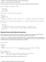
A risk table provides a project manager with a simple technique for risk projection.
2
A sample risk table is illustrated in Figure 6.2.
151
Risks
Size estimate may be significantly low
Larger number of users than planned
Less reuse than planned
End-users resist system
Delivery deadline will be tightened
Funding will be lost
Customer will change requirements
Technology will not meet expectations
Lack of training on tools
Staff inexperienced
Staff turnover will be high
PS
PS
PS
BU
BU
CU
PS
TE
DE
ST
ST
60%
30%
70%
40%
50%
40%
80%
30%
80%
30%
60%
2
3
2
3
2
1
2
1
3
2
2
Probability
Impact values:
1—catastrophic
2—critical
3—marginal
4—negligible
Impact RMMMCategory
•
•
•
FIGURE 6.2 Sample risk table prior to sorting
2 The risk table should be implemented as a spreadsheet model. This enables easy manipulation
and sorting of the entries.
PART TWO MANAGING SOFTWARE PROJECTS
152
A project team begins by listing all risks (no matter how remote) in the first col-
umn of the table. This can be accomplished with the help of the risk item check-
lists referenced in Section 6.3. Each risk is categorized in the second column (e.g.,
PS implies a project size risk, BU implies a business risk). The probability of occur-
rence of each risk is entered in the next column of the table. The probability value
for each risk can be estimated by team members individually. Individual team mem-
bers are polled in round-robin fashion until their assessment of risk probability
begins to converge.
Next, the impact of each risk is assessed. Each risk component is assessed using
the characterization presented in Figure 6.1, and an impact category is determined.
The categories for each of the four risk components—performance, support, cost, and
schedule—are averaged
3
to determine an overall impact value.
Once the first four columns of the risk table have been completed, the table is
sorted by probability and by impact. High-probability, high-impact risks percolate to
the top of the table, and low-probability risks drop to the bottom. This accomplishes
first-order risk prioritization.
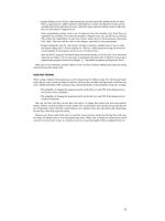
The project manager studies the resultant sorted table and defines a cutoff line.
The cutoff line (drawn horizontally at some point in the table) implies that only risks
that lie above the line will be given further attention. Risks that fall below the line are
re-evaluated to accomplish second-order prioritization. Referring to Figure 6.3, risk
impact and probability have a distinct influence on management concern. A risk fac-
1.0
0
Very low
Very high
Impact
Management
concern
High
Disregard
risk factor
Probability
of occurrence
FIGURE 6.3
Risk and
management
concern
Think hard about the
software you’re about
to build and ask
yourself, “What can go
wrong?” Create your
own list and ask other
members of the
software team to do
the same.
3 A weighted average can be used if one risk component has more significance for the project.
The risk table is sorted
by probability and
impact to rank risks.
CHAPTER 6 RISK ANALYSIS AND MANAGEMENT
tor that has a high impact but a very low probability of occurrence should not absorb
a significant amount of management time. However, high-impact risks with moder-
ate to high probability and low-impact risks with high probability should be carried
forward into the risk analysis steps that follow.
All risks that lie above the cutoff line must be managed. The column labeled
RMMM contains a pointer into a Risk Mitigation, Monitoring and Management Plan
or alternatively, a collection of risk information sheets developed for all risks that
lie above the cutoff. The RMMM plan and risk information sheets are discussed in
Sections 6.5 and 6.6.
Risk probability can be determined by making individual estimates and then devel-
oping a single consensus value. Although that approach is workable, more sophisti-
cated techniques for determining risk probability have been developed [AFC88]. Risk
drivers can be assessed on a qualitative probability scale that has the following val-
ues: impossible, improbable, probable, and frequent. Mathematical probability can
then be associated with each qualitative value (e.g., a probability of 0.7 to 1.0 implies
a highly probable risk).
6.4.2 Assessing Risk Impact
Three factors affect the consequences that are likely if a risk does occur: its nature,
its scope, and its timing. The nature of the risk indicates the problems that are likely
if it occurs. For example, a poorly defined external interface to customer hardware (a
technical risk) will preclude early design and testing and will likely lead to system
integration problems late in a project. The scope of a risk combines the severity (just
how serious is it?) with its overall distribution (how much of the project will be affected
or how many customers are harmed?). Finally, the timing of a risk considers when
and for how long the impact will be felt. In most cases, a project manager might want
the “bad news” to occur as soon as possible, but in some cases, the longer the delay,
the better.
Returning once more to the risk analysis approach proposed by the U.S. Air Force
[AFC88], the following steps are recommended to determine the overall consequences
of a risk:
1. Determine the average probability of occurrence value for each risk component.
2. Using Figure 6.1, determine the impact for each component based on the cri-
teria shown.
3. Complete the risk table and analyze the results as described in the preceding
sections.
The overall risk exposure, RE, is determined using the following relationship
[HAL98]:
RE = P x C
153
“Failure to prepare is
preparing to fail.”
Ben Franklin
How do we
assess the
consequences of a
risk?
?
PART TWO MANAGING SOFTWARE PROJECTS
154
where P is the probability of occurrence for a risk, and C is the the cost to the project
should the risk occur.
For example, assume that the software team defines a project risk in the follow-
ing manner:
Risk identification. Only 70 percent of the software components scheduled for reuse
will, in fact, be integrated into the application. The remaining functionality will have to
be custom developed.
Risk probability. 80% (likely).
Risk impact. 60 reusable software components were planned. If only 70 percent can be
used, 18 components would have to be developed from scratch (in addition to other cus-
tom software that has been scheduled for development). Since the average component is
100 LOC and local data indicate that the software engineering cost for each LOC is $14.00,
the overall cost (impact) to develop the components would be 18 x 100 x 14 = $25,200.
Risk exposure. RE = 0.80 x 25,200 ~ $20,200.
Risk exposure can be computed for each risk in the risk table, once an estimate of
the cost of the risk is made. The total risk exposure for all risks (above the cutoff in
the risk table) can provide a means for adjusting the final cost estimate for a project.
It can also be used to predict the probable increase in staff resources required at var-
ious points during the project schedule.
The risk projection and analysis techniques described in Sections 6.4.1 and 6.4.2
are applied iteratively as the software project proceeds. The project team should revisit
the risk table at regular intervals, re-evaluating each risk to determine when new cir-
cumstances cause its probability and impact to change. As a consequence of this
activity, it may be necessary to add new risks to the table, remove some risks that are
no longer relevant, and change the relative positions of still others.
6.4.3 Risk Assessment
At this point in the risk management process, we have established a set of triplets of
the form [CHA89]:
[r
i
, l
i
, x
i
]
where r
i
is risk, l
i
is the likelihood (probability) of the risk, and x
i
is the impact of the
risk. During risk assessment, we further examine the accuracy of the estimates that
were made during risk projection, attempt to rank the risks that have been uncov-
ered, and begin thinking about ways to control and/or avert risks that are likely to
occur.
For assessment to be useful, a risk referent level [CHA89] must be defined. For most
software projects, the risk components discussed earlier—performance, cost, sup-
port, and schedule—also represent risk referent levels. That is, there is a level for per-
Compare RE for all
risks to the cost
estimate for the
project. If RE is greater
than 50 percent of
project cost, the
viability of the project
must be evaluated.
CHAPTER 6 RISK ANALYSIS AND MANAGEMENT
formance degradation, cost overrun, support difficulty, or schedule slippage (or any
combination of the four) that will cause the project to be terminated. If a combina-
tion of risks create problems that cause one or more of these referent levels to be
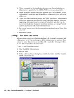
exceeded, work will stop. In the context of software risk analysis, a risk referent level
has a single point, called the referent point or break point, at which the decision to
proceed with the project or terminate it (problems are just too great) are equally
weighted. Figure 6.4 represents this situation graphically.
In reality, the referent level can rarely be represented as a smooth line on a graph.
In most cases it is a region in which there are areas of uncertainty; that is, attempt-
ing to predict a management decision based on the combination of referent values
is often impossible. Therefore, during risk assessment, we perform the following
steps:
1. Define the risk referent levels for the project.
2. Attempt to develop a relationship between each (r
i
, l
i
, x
i
) and each of the ref-
erent levels.
3. Predict the set of referent points that define a region of termination, bounded
by a curve or areas of uncertainty.
4. Try to predict how compound combinations of risks will affect a referent
level.
A detailed discussion of risk referent level is best left to books that are dedicated to
risk analysis (e.g., [CHA89], [ROW88]).
155
The risk referent level
establishes your
tolerance for pain.
Once risk exposure
exceeds the referent
level, the project may
be terminated.
Projected cost overrun
Projected schedule overrun
Referent point (cost value, time value)
Project termination will occur
FIGURE 6.4
Risk referent
level
PART TWO MANAGING SOFTWARE PROJECTS
156
6.5 RISK REFINEMENT
During early stages of project planning, a risk may be stated quite generally. As time
passes and more is learned about the project and the risk, it may be possible to refine
the risk into a set of more detailed risks, each somewhat easier to mitigate, monitor,
and manage.
One way to do this is to represent the risk in condition-transition-consequence (CTC)
format [GLU94]. That is, the risk is stated in the following form:
Given that <condition> then there is concern that (possibly) <consequence>.
Using the CTC format for the reuse risk noted in Section 6.4.2, we can write:
Given that all reusable software components must conform to specific design standards
and that some do not conform, then there is concern that (possibly) only 70 percent of the
planned reusable modules may actually be integrated into the as-built system, resulting in
the need to custom engineer the remaining 30 percent of components.
This general condition can be refined in the following manner:
Subcondition 1. Certain reusable components were developed by a third party with no
knowledge of internal design standards.
Subcondition 2. The design standard for component interfaces has not been solidified
and may not conform to certain existing reusable components.
Subcondition 3. Certain reusable components have been implemented in a language that
is not supported on the target environment.
The consequences associated with these refined subconditions remains the same (i.e.,
30 percent of software components must be customer engineered), but the refinement
helps to isolate the underlying risks and might lead to easier analysis and response.
6.6 RISK MITIGATION, MONITORING, AND MANAGEMENT
All of the risk analysis activities presented to this point have a single goal—to assist
the project team in developing a strategy for dealing with risk. An effective strategy
must consider three issues:
• risk avoidance
• risk monitoring
• risk management and contingency planning
If a software team adopts a proactive approach to risk, avoidance is always the best
strategy. This is achieved by developing a plan for risk mitigation. For example, assume
that high staff turnover is noted as a project risk, r
1
. Based on past history and man-
“If I take so many
precautions, it is
because I leave
nothing to chance.”
Napolean
What is a
good way to
describe a risk?
?
CHAPTER 6 RISK ANALYSIS AND MANAGEMENT
agement intuition, the likelihood, l
1
, of high turnover is estimated to be 0.70 (70 per-
cent, rather high) and the impact, x
1
, is projected at level 2. That is, high turnover will
have a critical impact on project cost and schedule.
To mitigate this risk, project management must develop a strategy for reducing
turnover. Among the possible steps to be taken are
• Meet with current staff to determine causes for turnover (e.g., poor working
conditions, low pay, competitive job market).
• Mitigate those causes that are under our control before the project
starts.
• Once the project commences, assume turnover will occur and develop tech-
niques to ensure continuity when people leave.
• Organize project teams so that information about each development activity
is widely dispersed.
• Define documentation standards and establish mechanisms to be sure that
documents are developed in a timely manner.
• Conduct peer reviews of all work (so that more than one person is "up to speed”).
• Assign a backup staff member for every critical technologist.
As the project proceeds, risk monitoring activities commence. The project manager
monitors factors that may provide an indication of whether the risk is becoming
more or less likely. In the case of high staff turnover, the following factors can be
monitored:
• General attitude of team members based on project pressures.
• The degree to which the team has jelled.
• Interpersonal relationships among team members.
• Potential problems with compensation and benefits.
• The availability of jobs within the company and outside it.
In addition to monitoring these factors, the project manager should monitor the effec-
tiveness of risk mitigation steps. For example, a risk mitigation step noted here called
for the definition of documentation standards and mechanisms to be sure that doc-
uments are developed in a timely manner. This is one mechanism for ensuring con-
tinuity, should a critical individual leave the project. The project manager should
monitor documents carefully to ensure that each can stand on its own and that each
imparts information that would be necessary if a newcomer were forced to join the
software team somewhere in the middle of the project.
Risk management and contingency planning assumes that mitigation efforts have
failed and that the risk has become a reality. Continuing the example, the project is
157
“We are ready for an
unforseen event that
may or may not
occur.”
Dan Quayle
W
ebRef
An excellent FAQ on risk
management can be
obtained at
www.sei.cmu.edu/
organization/
programs/sepm/
risk/risk.faq.html
PART TWO MANAGING SOFTWARE PROJECTS
158
well underway and a number of people announce that they will be leaving. If the mit-
igation strategy has been followed, backup is available, information is documented,
and knowledge has been dispersed across the team. In addition, the project manager
may temporarily refocus resources (and readjust the project schedule) to those func-
tions that are fully staffed, enabling newcomers who must be added to the team to
“get up to speed.” Those individuals who are leaving are asked to stop all work and
spend their last weeks in “knowledge transfer mode.” This might include video-based
knowledge capture, the development of “commentary documents,” and/or meeting
with other team members who will remain on the project.
It is important to note that RMMM steps incur additional project cost. For exam-
ple, spending the time to "backup" every critical technologist costs money. Part of
risk management, therefore, is to evaluate when the benefits accrued by the RMMM
steps are outweighed by the costs associated with implementing them. In essence,
the project planner performs a classic cost/benefit analysis. If risk aversion steps for
high turnover will increase both project cost and duration by an estimated 15 per-
cent, but the predominant cost factor is "backup," management may decide not to
implement this step. On the other hand, if the risk aversion steps are projected to
increase costs by 5 percent and duration by only 3 percent management will likely
put all into place.
For a large project, 30 or 40 risks may identified. If between three and seven risk
management steps are identified for each, risk management may become a project
in itself! For this reason, we adapt the Pareto 80–20 rule to software risk. Experience
indicates that 80 percent of the overall project risk (i.e., 80 percent of the potential
for project failure) can be accounted for by only 20 percent of the identified risks. The
work performed during earlier risk analysis steps will help the planner to determine
which of the risks reside in that 20 percent (e.g., risks that lead to the highest risk
exposure). For this reason, some of the risks identified, assessed, and projected may
not make it into the RMMM plan—they don't fall into the critical 20 percent (the risks
with highest project priority).
6.7 SAFETY RISKS AND HAZARDS
Risk is not limited to the software project itself. Risks can occur after the software
has been successfully developed and delivered to the customer. These risks are typ-
ically associated with the consequences of software failure in the field.
In the early days of computing, there was reluctance to use computers (and soft-
ware) to control safety critical processes such as nuclear reactors, aircraft flight con-
trol, weapons systems, and large-scale industrial processes. Although the probability
of failure of a well-engineered system was small, an undetected fault in a computer-
based control or monitoring system could result in enormous economic damage or,
worse, significant human injury or loss of life. But the cost and functional benefits of
If RE for a specific risk
is less than the cost of
risk mitigation, don’t
try to mitigate the risk
but continue to
monitor it.
CHAPTER 6 RISK ANALYSIS AND MANAGEMENT
computer-based control and monitoring far outweigh the risk. Today, computer hard-
ware and software are used regularly to control safety critical systems.
When software is used as part of a control system, complexity can increase by an
order of magnitude or more. Subtle design faults induced by human error—some-
thing that can be uncovered and eliminated in hardware-based conventional con-
trol—become much more difficult to uncover when software is used.
Software safety and hazard analysis [LEV95] are software quality assurance activ-
ities (Chapter 8) that focus on the identification and assessment of potential hazards
that may affect software negatively and cause an entire system to fail. If hazards can
be identified early in the software engineering process, software design features can
be specified that will either eliminate or control potential hazards.
6.8 THE RMMM PLAN
A risk management strategy can be included in the software project plan or the risk
management steps can be organized into a separate Risk Mitigation, Monitoring and
Management Plan. The RMMM plan documents all work performed as part of risk
analysis and is used by the project manager as part of the overall project plan.
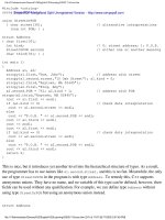
Some software teams do not develop a formal RMMM document. Rather, each risk
is documented individually using a risk information sheet (RIS) [WIL97]. In most cases,
the RIS is maintained using a database system, so that creation and information entry,
priority ordering, searches, and other analysis may be accomplished easily. The for-
mat of the RIS is illustrated in Figure 6.5.
Once RMMM has been documented and the project has begun, risk mitigation and
monitoring steps commence. As we have already discussed, risk mitigation is a prob-
lem avoidance activity. Risk monitoring is a project tracking activity with three pri-
mary objectives: (1) to assess whether predicted risks do, in fact, occur; (2) to ensure
that risk aversion steps defined for the risk are being properly applied; and (3) to col-
lect information that can be used for future risk analysis. In many cases, the prob-
lems that occur during a project can be traced to more than one risk. Another job of
risk monitoring is to attempt to allocate origin (what risk(s) caused which problems
throughout the project).
6.9 SUMMARY
Whenever a lot is riding on a software project, common sense dictates risk analy-
sis. And yet, most software project managers do it informally and superficially, if
they do it at all. The time spent identifying, analyzing, and managing risk pays itself
back in many ways: less upheaval during the project, a greater ability to track and
control a project, and the confidence that comes with planning for problems before
they occur.
159
RMMM Plan
W
ebRef
A voluminous database
containing all entries from
the ACM’s Forum on Risks
to the Public can be found
at
catless.ncl.ac.uk/
Risks/search.html
PART TWO MANAGING SOFTWARE PROJECTS
160
Risk analysis can absorb a significant amount of project planning effort. Identifi-
cation, projection, assessment, management, and monitoring all take time. But the
effort is worth it. To quote Sun Tzu, a Chinese general who lived 2500 years ago, "If
you know the enemy and know yourself, you need not fear the result of a hundred
battles." For the software project manager, the enemy is risk.
REFERENCES
[AFC88] Software Risk Abatement, AFCS/AFLC Pamphlet 800-45, U.S. Air Force, Sep-
tember 30, 1988.
[BOE89] Boehm, B.W., Software Risk Management, IEEE Computer Society Press,
1989.
[CHA89] Charette, R.N., Software Engineering Risk Analysis and Management, McGraw-
Hill/Intertext, 1989.
Risk information sheet
Date: 5/9/02 Prob: 80% Impact: highRisk ID: P02-4-32
Description:
Only 70 percent of the software components scheduled for reuse will, in fact, be
integrated into the application. The remaining functionality will have to be custom
developed.
Refinement/context:
Subcondition 1: Certain reusable components were developed by a third party
with no knowledge of internal design standards.
Subcondition 2: The design standard for component interfaces has not been
solidified and may not conform to certain existing reusable components.
Subcondition 3: Certain reusable components have been implemented in a
language that is not supported on the target environment.
Mitigation/monitoring:
1. Contact third party to determine conformance with design standards.
2. Press for interface standards completion; consider component structure when
deciding on interface protocol.
3. Check to determine number of components in subcondition 3 category; check
to determine if language support can be acquired.
Management/contingency plan/trigger:
RE
computed to be $20,200. Allocate this amount within project contingency cost.
Develop revised schedule assuming that 18 additional components will have to be
custom built; allocate staff accordingly.
Trigger: Mitigation steps unproductive as of 7/1/02
Current status:
5/12/02: Mitigation steps initiated.
Originator: D. Gagne Assigned: B. Laster
FIGURE 6.5
Risk
information
sheet [WIL97
]
CHAPTER 6 RISK ANALYSIS AND MANAGEMENT
[CHA92] Charette, R.N., “Building Bridges over Intelligent Rivers,” American Pro-
grammer, vol. 5, no. 7, September, 1992, pp. 2–9.
[DRU75] Drucker, P., Management, W. H. Heinemann, 1975.
[GIL88] Gilb, T., Principles of Software Engineering Management, Addison-Wesley, 1988.
[GLU94] Gluch, D.P., “A Construct for Describing Software Development Risks,”
CMU/SEI-94-TR-14, Software Engineering Institute, 1994.
[HAL98] Hall, E.M., Managing Risk: Methods for Software Systems Development,
Addison-Wesley, 1998.
[HIG95] Higuera, R.P., “Team Risk Management,” CrossTalk, U.S. Dept. of Defense,
January 1995, p. 2–4.
[KAR96] Karolak, D.W., Software Engineering Risk Management, IEEE Computer Soci-
ety Press, 1996.
[KEI98] Keil, M., et al., “A Framework for Identifying Software Project Risks,” CACM,
vol. 41, no. 11, November 1998, pp. 76–83.
[LEV95] Leveson, N.G., Safeware: System Safety and Computers, Addison-Wesley,
1995.
[ROW88] Rowe, W.D., An Anatomy of Risk, Robert E. Krieger Publishing Co., 1988.
[SEI93] “Taxonomy-Based Risk Identification,” Software Engineering Institute,
CMU/SEI-93-TR-6, 1993.
[THO92] Thomsett, R., “The Indiana Jones School of Risk Management,” American
Programmer, vol. 5, no. 7, September 1992, pp. 10–18.
[WIL97] Williams, R.C, J.A. Walker, and A.J. Dorofee, “Putting Risk Management into
Practice,” IEEE Software, May 1997, pp. 75–81.
PROBLEMS AND POINTS TO PONDER
6.1. Provide five examples from other fields that illustrate the problems associated
with a reactive risk strategy.
6.2. Describe the difference between “known risks” and “predictable risks.”
6.3. Add three additional questions or topics to each of the risk item checklists pre-
sented at the SEPA Web site.
6.4. You’ve been asked to build software to support a low-cost video editing sys-
tem. The system accepts videotape as input, stores the video on disk, and then allows
the user to do a wide range of edits to the digitized video. The result can then be out-
put to tape. Do a small amount of research on systems of this type and then make a
list of technology risks that you would face as you begin a project of this type.
6.5. You’re the project manager for a major software company. You’ve been asked
to lead a team that’s developing “next generation” word-processing software (see
Section 3.4.2 for a brief description). Create a risk table for the project.
161
PART TWO MANAGING SOFTWARE PROJECTS
162
6.6. Describe the difference between risk components and risk drivers.
6.7. Develop a risk mitigation strategy and specific risk mitigation activities for three
of the risks noted in Figure 6.2.
6.8. Develop a risk monitoring strategy and specific risk monitoring activities for
three of the risks noted in Figure 6.2. Be sure to identify the factors that you’ll be mon-
itoring to determine whether the risk is becoming more or less likely.
6.9. Develop a risk management strategy and specific risk management activities
for three of the risks noted in Figure 6.2.
6.10. Attempt to refine three of the risks noted in Figure 6.2 and then create risk
information sheets for each.
6.11. Represent three of the risks noted in Figure 6.2 using a CTC format.
6.12. Recompute the risk exposure discussed in Section 6.4.2 when cost/LOC is $16
and the probability is 60 percent.
6.13. Can you think of a situation in which a high-probability, high-impact risk would
not be considered as part of your RMMM plan?
6.14. Referring the the risk referent shown on Figure 6.4, would the curve always
have the symmetric arc shown or would there be situations in which the curve would
be more distorted. If so, suggest a scenario in which this might happen.
6.15. Do some research on software safety issues and write a brief paper on the
subject. Do a Web search to get current information.
6.16. Describe five software application areas in which software safety and hazard
analysis would be a major concern.
FURTHER READINGS AND INFORMATION SOURCES
The software risk management literature has expanded significantly in recent years.
Hall [HAL98] presents one of the more thorough treatments of the subject. Karolak
[KAR96] has written a guidebook that introduces an easy-to-use risk analysis model
with worthwhile checklists and questionnaires. A useful snapshot of risk assessment
has been written by Grey (Practical Risk Assessment for Project Management, Wiley,
1995). His abbreviated treatment provides a good introduction to the subject. Addi-
tional books worth examining include
Chapman, C.B. and S. Ward, Project Risk Management: Processes, Techniques and Insights,
Wiley, 1997.
Schuyler, J.R., Decision Analysis in Projects, Project Management Institute Publications, 1997.
Wideman, R.M. (editor), Project & Program Risk Management: A Guide to Managing Project
Risks and Opportunities, Project Management Institute Publications, 1998.
CHAPTER 6 RISK ANALYSIS AND MANAGEMENT
Capers Jones (Assessment and Control of Software Risks, Prentice-Hall, 1994) pre-
sents a detailed discussion of software risks that includes data collected from hun-
dreds of software projects. Jones defines 60 risk factors that can affect the outcome
of software projects. Boehm [BOE89] suggests excellent questionnaire and checklist
formats that can prove invaluable in identifying risk. Charette [CHA89] presents a
detailed treatment of the mechanics of risk analysis, calling on probability theory and
statistical techniques to analyze risks. In a companion volume, Charette (Application
Strategies for Risk Analysis, McGraw-Hill, 1990) discusses risk in the context of both
system and software engineering and suggests pragmatic strategies for risk man-
agement. Gilb (Principles of Software Engineering Management, Addison-Wesley, 1988)
presents a set of "principles" (which are often amusing and sometimes profound) that
can serve as a worthwhile guide for risk management.
The March 1995 issue of American Programmer, the May 1997 issue of IEEE Soft-
ware, and the June 1998 issue of the Cutter IT Journal all are dedicated to risk man-
agement.
The Software Engineering Institute has published many detailed reports and guide-
books on risk analysis and management. The Air Force Systems Command pamphlet
AFSCP 800-45 [AFC88] describes risk identification and reduction techniques. Every
issue of the ACM Software Engineering Notes has a section entitled "Risks to the Pub-
lic" (editor, P.G. Neumann). If you want the latest and best software horror stories,
this is the place to go.
A wide variety of information sources on risk analysis and management is avail-
able on the Internet. An up-to-date list of World Wide Web references that are rele-
vant to risk can be found at the SEPA Web site:
/>163
CHAPTER
KEY
CONCEPTS
adaptation
criteria . . . . . . . . 174
critical path. . . . . 181
earned value . . . 186
error tracking. . . 187
lateness . . . . . . . 166
people and effort170
project plan . . . . 189
project tracking . 185
scheduling
principles . . . . . . 168
task network. . . 180
task set . . . . . . . 172
timeline chart. . . 182
work breakdown
structure. . . . . . . 181
I
n the late 1960s, a bright-eyed young engineer was chosen to "write" a com-
puter program for an automated manufacturing application. The reason for
his selection was simple. He was the only person in his technical group who
had attended a computer programming seminar. He knew the ins and outs of
assembly language and FORTRAN but nothing about software engineering and
even less about project scheduling and tracking.
His boss gave him the appropriate manuals and a verbal description of what
had to be done. He was informed that the project must be completed in two
months.
He read the manuals, considered his approach, and began writing code.
After two weeks, the boss called him into his office and asked how things were
going.
"Really great," said the young engineer with youthful enthusiasm, "This was
much simpler than I thought. I'm probably close to 75 percent finished."
The boss smiled. "That's really terrific," he said, encouraging the young
engineer to keep up the good work. They planned to meet again in a week’s
time.
A week later the boss called the engineer into his office and asked, "Where
are we?"
7
PROJECT SCHEDULING AND
TRACKING
What is it? You’ve selected
an appropriate process model,
you’ve identified the software
engineering tasks that have to be performed, you
estimated the amount of work and the number of
people, you know the deadline, you’ve even con-
sidered the risks. Now it’s time to connect the dots.
That is, you have to create a network of software
engineering tasks that will enable you to get the
job done on time. Once the network is created,
you have to assign responsibility for each task,
make sure it gets done, and adapt the network as
risks become reality. In a nutshell, that’s software
project scheduling and tracking.
Who does it? At the project level, software proj-ect
managers using information solicited from soft-
ware engineers. At an individual level, software
engineers themselves.
Why is it important? In order to build a complex sys-
tem, many software engineering tasks occur in
parallel, and the result of work performed during
one task may have a profound effect on work to
be conducted in another task. These interdepen-
dencies are very difficult to understand without a
schedule. lt’s also virtually impossible to assess
progress on a moderate or large software project
without a detailed schedule.
What are the steps? The software engineering
tasks dictated by the software process model are
refined for the functionality to be built. Effort and
duration are allocated to each task and a task
network (also called an “activity network”) is
QUICK
LOOK
PART TWO MANAGING SOFTWARE PROJECTS
166
"Everything's going well," said the youngster, “but I've run into a few small snags.
I'll get them ironed out and be back on track soon."
"How does the deadline look?" the boss asked.
"No problem," said the engineer. "I'm close to 90 percent complete."
If you've been working in the software world for more than a few years, you can fin-
ish the story. It'll come as no surprise that the young engineer
1
stayed 90 percent
complete for the entire project duration and finished (with the help of others) only
one month late.
This story has been repeated tens of thousands of times by software developers
during the past three decades. The big question is why?
7.1 BASIC CONCEPTS
Although there are many reasons why software is delivered late, most can be traced
to one or more of the following root causes:
• An unrealistic deadline established by someone outside the software devel-
opment group and forced on managers and practitioner's within the group.
• Changing customer requirements that are not reflected in schedule changes.
• An honest underestimate of the amount of effort and/or the number of
resources that will be required to do the job.
• Predictable and/or unpredictable risks that were not considered when the
project commenced.
• Technical difficulties that could not have been foreseen in advance.
• Human difficulties that could not have been foreseen in advance.
• Miscommunication among project staff that results in delays.
• A failure by project management to recognize that the project is falling
behind schedule and a lack of action to correct the problem.
Aggressive (read "unrealistic") deadlines are a fact of life in the software business.
Sometimes such deadlines are demanded for reasons that are legitimate, from the
created in a manner that enables
the software team to meet the
delivery deadline established.
What is the work product? The project schedule and
related information are produced.
How do I ensure that I’ve done it right? Proper sched-
uling requires that (1) all tasks appear in the net-
work, (2) effort and timing are intelligently allo-
cated to each task, (3) interdependencies between
tasks are properly indicated, (4) resources are allo-
cated for the work to be done, and (5) closely
spaced milestones are provided so that progress
can be tracked.
QUICK
LOOK
1 If you’re wondering whether this story is autobiographical, it is!
“Excessive or
irrational schedules
are probably the
single most
destructive influence
in all of software.”
Capers Jones
CHAPTER 7 PROJECT SCHEDULING AND TRACKING
point of view of the person who sets the deadline. But common sense says that legit-
imacy must also be perceived by the people doing the work.
7.1.1 Comments on “Lateness”
Napoleon once said: "Any commander in chief who undertakes to carry out a plan
which he considers defective is at fault; he must put forth his reasons, insist on the
plan being changed, and finally tender his resignation rather than be the instrument
of his army's downfall." These are strong words that many software project man-
agers should ponder.
The estimation and risk analysis activities discussed in Chapters 5 and 6, and the
scheduling techniques described in this chapter are often implemented under the
constraint of a defined deadline. If best estimates indicate that the deadline is unre-
alistic, a competent project manager should "protect his or her team from undue
[schedule] pressure . . . [and] reflect the pressure back to its originators" [PAG85].
To illustrate, assume that a software development group has been asked to build
a real-time controller for a medical diagnostic instrument that is to be introduced to
the market in nine months. After careful estimation and risk analysis, the software
project manager comes to the conclusion that the software, as requested, will require
14 calendar months to create with available staff. How does the project manager
proceed?
It is unrealistic to march into the customer's office (in this case the likely customer
is marketing/sales) and demand that the delivery date be changed. External market
pressures have dictated the date, and the product must be released. It is equally fool-
hardy to refuse to undertake the work (from a career standpoint). So, what to do?
The following steps are recommended in this situation:
1. Perform a detailed estimate using historical data from past projects. Deter-
mine the estimated effort and duration for the project.
2. Using an incremental process model (Chapter 2), develop a software engi-
neering strategy that will deliver critical functionality by the imposed dead-
line, but delay other functionality until later. Document the plan.
3. Meet with the customer and (using the detailed estimate), explain why the
imposed deadline is unrealistic. Be certain to note that all estimates are
based on performance on past projects. Also be certain to indicate the per-
cent improvement that would be required to achieve the deadline as it cur-
rently exists.
2
The following comment is appropriate:
"I think we may have a problem with the delivery date for the XYZ controller
software. I've given each of you an abbreviated breakdown of production
167
2 If the percent of improvement is 10 to 25 percent, it may actually be possible to get the job done.
But, more likely, the percent of improvement in team performance must be greater than 50 per-
cent. This is an unrealistic expectation.
“I love deadlines. I
like the whooshing
sound they make as
they fly by.”
Douglas Adams
What should
we do when
management
demands that we
make a deadline
that is
impossible?
?
PART TWO MANAGING SOFTWARE PROJECTS
168
rates for past projects and an estimate that we've done a number of different
ways. You'll note that I've assumed a 20 percent improvement in past pro-
duction rates, but we still get a delivery date that's 14 calendar months rather
than 9 months away."
4. Offer the incremental development strategy as an alternative:
“We have a few options, and I'd like you to make a decision based on them.
First, we can increase the budget and bring on additional resources so that
we'll have a shot at getting this job done in nine months. But understand that
this will increase risk of poor quality due to the tight timeline.
3
Second, we
can remove a number of the software functions and capabilities that you're
requesting. This will make the preliminary version of the product somewhat
less functional, but we can announce all functionality and then deliver over
the 14 month period. Third, we can dispense with reality and wish the project
complete in nine months. We'll wind up with nothing that can be delivered to
a customer. The third option, I hope you'll agree, is unacceptable. Past his-
tory and our best estimates say that it is unrealistic and a recipe for disaster."
There will be some grumbling, but if solid estimates based on good historical data
are presented, it's likely that negotiated versions of option 1 or 2 will be chosen. The
unrealistic deadline evaporates.
7.1.2 Basic Principles
Fred Brooks, the well-known author of The Mythical Man-Month [BRO95], was once
asked how software projects fall behind schedule. His response was as simple as it
was profound: "One day at a time."
The reality of a technical project (whether it involves building a hydroelectric plant
or developing an operating system) is that hundreds of small tasks must occur to
accomplish a larger goal. Some of these tasks lie outside the mainstream and may
be completed without worry about impact on project completion date. Other tasks
lie on the "critical” path.
4
If these "critical" tasks fall behind schedule, the completion
date of the entire project is put into jeopardy.
The project manager’s objective is to define all project tasks, build a network that
depicts their interdependencies, identify the tasks that are critical within the network,
and then track their progress to ensure that delay is recognized "one day at a time."
To accomplish this, the manager must have a schedule that has been defined at a
degree of resolution that enables the manager to monitor progress and control the
project.
Software project scheduling is an activity that distributes estimated effort across the
planned project duration by allocating the effort to specific software engineering tasks.
3 You might also add that adding more people does not reduce calendar time proportionally.
4 The critical path will be discussed in greater detail later in this chapter.
The tasks required to
achieve the project
manager’s objective
should not be
performed manually.
There are many
excellent project
scheduling tools. Use
them.
XRef
Incremental process
models are described in
Chapter 2.
CHAPTER 7 PROJECT SCHEDULING AND TRACKING
It is important to note, however, that the schedule evolves over time. During early
stages of project planning, a macroscopic schedule is developed. This type of sched-
ule identifies all major software engineering activities and the product functions to
which they are applied. As the project gets under way, each entry on the macroscopic
schedule is refined into a detailed schedule. Here, specific software tasks (required to
accomplish an activity) are identified and scheduled.
Scheduling for software engineering projects can be viewed from two rather dif-
ferent perspectives. In the first, an end-date for release of a computer-based system
has already (and irrevocably) been established. The software organization is con-
strained to distribute effort within the prescribed time frame. The second view of soft-
ware scheduling assumes that rough chronological bounds have been discussed but
that the end-date is set by the software engineering organization. Effort is distributed
to make best use of resources and an end-date is defined after careful analysis of the
software. Unfortunately, the first situation is encountered far more frequently than
the second.
Like all other areas of software engineering, a number of basic principles guide
software project scheduling:
Compartmentalization. The project must be compartmentalized into a
number of manageable activities and tasks. To accomplish compartmental-
ization, both the product and the process are decomposed (Chapter 3).
Interdependency. The interdependency of each compartmentalized activity
or task must be determined. Some tasks must occur in sequence while others
can occur in parallel. Some activities cannot commence until the work prod-
uct produced by another is available. Other activities can occur independently.
Time allocation. Each task to be scheduled must be allocated some num-
ber of work units (e.g., person-days of effort). In addition, each task must be
assigned a start date and a completion date that are a function of the interde-
pendencies and whether work will be conducted on a full-time or part-time
basis.
Effort validation. Every project has a defined number of staff members. As
time allocation occurs, the project manager must ensure that no more than
the allocated number of people have been scheduled at any given time. For
example, consider a project that has three assigned staff members (e.g., 3
person-days are available per day of assigned effort
5
). On a given day, seven
concurrent tasks must be accomplished. Each task requires 0.50 person days
of effort. More effort has been allocated than there are people to do the work.
Defined responsibilities. Every task that is scheduled should be assigned
to a specific team member.
169
“Overly optimistic
scheduling doesn’t
result in shorter
actual schedules, it
results in longer
ones.”
Steve McConnell
5 In reality, less than three person-days are available because of unrelated meetings, sickness,
vacation, and a variety of other reasons. For our purposes, however, we assume 100 percent
availability.
When you develop a
schedule, compartmen-
talize the work,
represent task inter-
dependencies, allocate
effort and time to each
task, define respon-
sibilities for the work
to be done, and define
outcomes and
milestones.
PART TWO MANAGING SOFTWARE PROJECTS
170
Defined outcomes. Every task that is scheduled should have a defined out-
come. For software projects, the outcome is normally a work product (e.g.,
the design of a module) or a part of a work product. Work products are often
combined in deliverables.
Defined milestones. Every task or group of tasks should be associated with
a project milestone. A milestone is accomplished when one or more work
products has been reviewed for quality (Chapter 8) and has been approved.
Each of these principles is applied as the project schedule evolves.
7.2 THE RELATIONSHIP BETWEEN PEOPLE AND EFFORT
In a small software development project a single person can analyze requirements,
perform design, generate code, and conduct tests. As the size of a project increases,
more people must become involved. (We can rarely afford the luxury of approach-
ing a ten person-year effort with one person working for ten years!)
There is a common myth (discussed in Chapter 1) that is still believed by many
managers who are responsible for software development effort: "If we fall behind
schedule, we can always add more programmers and catch up later in the project."
Unfortunately, adding people late in a project often has a disruptive effect on the proj-
ect, causing schedules to slip even further. The people who are added must learn the
system, and the people who teach them are the same people who were doing the
work. While teaching, no work is done, and the project falls further behind.
In addition to the time it takes to learn the system, more people increase the num-
ber of communication paths and the complexity of communication throughout a proj-
ect. Although communication is absolutely essential to successful software
development, every new communication path requires additional effort and there-
fore additional time.
7.2.1 An Example
Consider four software engineers, each capable of producing 5000 LOC/year when
working on an individual project. When these four engineers are placed on a team
project, six potential communication paths are possible. Each communication path
requires time that could otherwise be spent developing software. We shall assume
that team productivity (when measured in LOC) will be reduced by 250 LOC/year for
each communication path, due to the overhead associated with communication.
Therefore, team productivity is 20,000 Ϫ (250 x 6) = 18,500 LOC/year—7.5 percent
less than what we might expect.
6
6 It is possible to pose a counterargument: Communication, if it is effective, can enhance the qual-
ity of the work being performed, thereby reducing the amount of rework and increasing the indi-
vidual productivity of team members. The jury is still out!
If you must add people
to a late project, be
certain that you’ve
assigned them work
that is highly
compartmentalized.
CHAPTER 7 PROJECT SCHEDULING AND TRACKING
The one-year project on which the team is working falls behind schedule, and with
two months remaining, two additional people are added to the team. The number of
communication paths escalates to 14. The productivity input of the new staff is the
equivalent of 840 x 2 = 1680 LOC for the two months remaining before delivery. Team
productivity now is 20,000 + 1680 Ϫ (250 x 14) = 18,180 LOC/year.
Although the example is a gross oversimplification of real-world circumstances,
it does illustrate another key point: The relationship between the number of people
working on a software project and overall productivity is not linear.
Based on the people/work relationship, are teams counterproductive? The answer
is an emphatic "no," if communication improves software quality. In fact, formal
technical reviews (see Chapter 8) conducted by software teams can lead to better
analysis and design, and more important, can reduce the number of errors that go
undetected until testing (thereby reducing testing effort). Hence, productivity and
quality, when measured by time to project completion and customer satisfaction, can
actually improve.
7.2.2. An Empirical Relationship
Recalling the software equation [PUT92] that was introduced in Chapter 5, we can
demonstrate the highly nonlinear relationship between chronological time to com-
plete a project and human effort applied to the project. The number of delivered
lines of code (source statements), L, is related to effort and development time by
the equation:
L = P x E
1/3
t
4/3
where E is development effort in person-months, P is a productivity parameter that
reflects a variety of factors that lead to high-quality software engineering work (typ-
ical values for P range between 2,000 and 12,000), and t is the project duration in cal-
endar months.
Rearranging this software equation, we can arrive at an expression for develop-
ment effort E:
E = L
3
/( P
3
t
4
) (7-1)
where E is the effort expended (in person-years) over the entire life cycle for software
development and maintenance and t is the development time in years. The equation
for development effort can be related to development cost by the inclusion of a bur-
dened labor rate factor ($/person-year).
This leads to some interesting results. Consider a complex, real-time software proj-
ect estimated at 33,000 LOC, 12 person-years of effort. If eight people are assigned
to the project team, the project can be completed in approximately 1.3 years. If, how-
ever, we extend the end-date to 1.75 years, the highly nonlinear nature of the model
described in Equation (7-1) yields:
E = L
3
/( P
3
t
4
) ~ 3.8 person-years.
171
The relationship
between the number
of people working on a
software project and
overall productivity is
not linear.
As the deadline
becomes tighter and
tighter, you reach a
point at which the
work cannot be
completed on
schedule, regardless of
the number of people
doing the work. Face
reality and define a
new delivery date.
PART TWO MANAGING SOFTWARE PROJECTS
172
This implies that, by extending the end-date six months, we can reduce the number
of people from eight to four! The validity of such results is open to debate, but the
implication is clear: Benefit can be gained by using fewer people over a somewhat
longer time span to accomplish the same objective.
7.2.3 Effort Distribution
Each of the software project estimation techniques discussed in Chapter 5 leads to
estimates of work units (e.g., person-months) required to complete software devel-
opment. A recommended distribution of effort across the definition and development
phases is often referred to as the 40–20–40 rule.
7
Forty percent of all effort is allocated
to front-end analysis and design. A similar percentage is applied to back-end testing.
You can correctly infer that coding (20 percent of effort) is de-emphasized.
This effort distribution should be used as a guideline only. The characteristics of
each project must dictate the distribution of effort. Work expended on project plan-
ning rarely accounts for more than 2–3 percent of effort, unless the plan commits an
organization to large expenditures with high risk. Requirements analysis may com-
prise 10–25 percent of project effort. Effort expended on analysis or prototyping should
increase in direct proportion with project size and complexity. A range of 20 to 25
percent of effort is normally applied to software design. Time expended for design
review and subsequent iteration must also be considered.
Because of the effort applied to software design, code should follow with relatively
little difficulty. A range of 15–20 percent of overall effort can be achieved. Testing and
subsequent debugging can account for 30–40 percent of software development effort.
The criticality of the software often dictates the amount of testing that is required. If
software is human rated (i.e., software failure can result in loss of life), even higher
percentages are typical.
7.3 DEFINING A TASK SET FOR THE SOFTWARE PROJECT
A number of different process models were described in Chapter 2. These models
offer different paradigms for software development. Regardless of whether a soft-
ware team chooses a linear sequential paradigm, an iterative paradigm, an evolu-
tionary paradigm, a concurrent paradigm or some permutation, the process model
is populated by a set of tasks that enable a software team to define, develop, and ulti-
mately support computer software.
No single set of tasks is appropriate for all projects. The set of tasks that would be
appropriate for a large, complex system would likely be perceived as overkill for a
small, relatively simple software product. Therefore, an effective software process
7 Today, more than 40 percent of all project effort is often recommended for analysis and design
tasks for large software development projects. Hence, the name 40–20–40 no longer applies in a
strict sense.
How much
effort should
be expended on
each of the major
software
engineering
tasks?
?
CHAPTER 7 PROJECT SCHEDULING AND TRACKING
should define a collection of task sets, each designed to meet the needs of different
types of projects.
A task set is a collection of software engineering work tasks, milestones, and deliv-
erables that must be accomplished to complete a particular project. The task set to
be chosen must provide enough discipline to achieve high software quality. But, at
the same time, it must not burden the project team with unnecessary work.
Task sets are designed to accommodate different types of projects and different
degrees of rigor. Although it is difficult to develop a comprehensive taxonomy of soft-
ware project types, most software organizations encounter the following projects:
1. Concept development projects that are initiated to explore some new business
concept or application of some new technology.
2. New application development projects that are undertaken as a consequence
of a specific customer request.
3. Application enhancement projects that occur when existing software under-
goes major modifications to function, performance, or interfaces that are
observable by the end-user.
4. Application maintenance projects that correct, adapt, or extend existing soft-
ware in ways that may not be immediately obvious to the end-user.
5. Reengineering projects that are undertaken with the intent of rebuilding an
existing (legacy) system in whole or in part.
Even within a single project type, many factors influence the task set to be chosen.
When taken in combination, these factors provide an indication of the degree of rigor
with which the software process should be applied.
7.3.1 Degree of Rigor
Even for a project of a particular type, the degree of rigor with which the software
process is applied may vary significantly. The degree of rigor is a function of many
project characteristics. As an example, small, non-business-critical projects can gen-
erally be addressed with somewhat less rigor than large, complex business-critical
applications. It should be noted, however, that all projects must be conducted in a
manner that results in timely, high-quality deliverables. Four different degrees of rigor
can be defined:
Casual. All process framework activities (Chapter 2) are applied, but only a
minimum task set is required. In general, umbrella tasks will be minimized
and documentation requirements will be reduced. All basic principles of soft-
ware engineering are still applicable.
Structured. The process framework will be applied for this project. Frame-
work activities and related tasks appropriate to the project type will be
applied and umbrella activities necessary to ensure high quality will be
173
A “task set” is a
collection of software
engineering tasks,
milestones, and
deliverables.
The task set will grow
in size and complexity
as the degree of rigor
grows.
PART TWO MANAGING SOFTWARE PROJECTS
174
applied. SQA, SCM, documentation, and measurement tasks will be con-
ducted in a streamlined manner.
Strict. The full process will be applied for this project with a degree of disci-
pline that will ensure high quality. All umbrella activities will be applied and
robust work products will be produced.
Quick reaction. The process framework will be applied for this project, but
because of an emergency situation
8
only those tasks essential to maintaining
good quality will be applied. “Back-filling” (i.e., developing a complete set of
documentation, conducting additional reviews) will be accomplished after
the application/product is delivered to the customer.
The project manager must develop a systematic approach for selecting the degree
of rigor that is appropriate for a particular project. To accomplish this, project adap-
tation criteria are defined and a task set selector value is computed.
7.3.2 Defining Adaptation Criteria
Adaptation criteria are used to determine the recommended degree of rigor with which
the software process should be applied on a project. Eleven adaptation criteria [PRE99]
are defined for software projects:
• Size of the project
• Number of potential users
• Mission criticality
• Application longevity
• Stability of requirements
• Ease of customer/developer communication
• Maturity of applicable technology
• Performance constraints
• Embedded and nonembedded characteristics
• Project staff
• Reengineering factors
Each of the adaptation criteria is assigned a grade that ranges between 1 and 5, where
1 represents a project in which a small subset of process tasks are required and over-
all methodological and documentation requirements are minimal, and 5 represents
a project in which a complete set of process tasks should be applied and overall
methodological and documentation requirements are substantial.
8 Emergency situations should be rare (they should not occur on more than 10 percent of all work
conducted within the software engineering context). An emergency is not the same as a project
with tight time constraints.
Adaptable Process Model
If everything is an
emergency, there’s
something wrong with
your software process
or with the people who
manage the business
or both.
CHAPTER 7 PROJECT SCHEDULING AND TRACKING
7.3.3 Computing a Task Set Selector Value
To select the appropriate task set for a project, the following steps should be con-
ducted:
1. Review each of the adaptation criteria in Section 7.3.2 and assign the appro-
priate grades (1 to 5) based on the characteristics of the project. These grades
should be entered into Table 7.1.
2. Review the weighting factors assigned to each of the criteria. The value of a
weighting factor ranges from 0.8 to 1.2 and provides an indication of the rel-
ative importance of a particular adaptation criterion to the types of software
developed within the local environment. If modifications are required to bet-
ter reflect local circumstances, they should be made.
3. Multiply the grade entered in Table 7.1 by the weighting factor and by the
entry point multiplier for the type of project to be undertaken. The entry point
multiplier takes on a value of 0 or 1 and indicates the relevance of the adap-
tation criterion to the project type. The result of the product
grade x weighting factor x entry point multiplier
is placed in the Product column of Table 7.1 for each adaptation criteria indi-
vidually.
4. Compute the average of all entries in the Product column and place the result
in the space marked task set selector (TSS). This value will be used to help
select the task set that is most appropriate for the project.
175
How do we
choose the
appropriate task
set for our
project?
?
TABLE 7.1 COMPUTING THE TASK SET SELECTOR
Adaptation Criteria Grade Weight Entry Point Multiplier Product
Conc. NDev. Enhan. Maint. Reeng.
Size of project _____ 1.20 0 1 1 1 1 _____
Number of users _____ 1.10 0 1 1 1 1 _____
Business criticality _____ 1.10 0 1 1 1 1 _____
Longevity _____ 0.90 0 1 1 0 0 _____
Stability of requirements _____ 1.20 0 1 1 1 1 _____
Ease of communication _____ 0.90 1 1 1 1 1 _____
Maturity of technology _____ 0.90 1 1 0 0 1 _____
Performance constraints _____ 0.80 0 1 1 0 1 _____
Embedded/nonembedded _____ 1.20 1 1 1 0 1 _____
Project staffing _____ 1.00 1 1 1 1 1 _____
Interoperability _____ 1.10 0 1 1 1 1 _____
Reengineering factors _____ 1.20 0 0 0 0 1 _____
Task set selector (TSS) _____