Hiểu biết về mô hình hóa động pptx
Bạn đang xem bản rút gọn của tài liệu. Xem và tải ngay bản đầy đủ của tài liệu tại đây (1.01 MB, 50 trang )
Understanding
Dynamic Modeling
Chapter 7
An object-oriented design should represent the structural
and behavioral aspects of a software system. Static
modeling is used to represent the structural constituents of
a software system. Dynamic modeling is used to represent
the behavior of the structural constituents. Dynamic
modeling uses various types of diagrams, such as
interaction, state, and activity diagrams.
This chapter explains the concept of dynamic modeling.
In addition, it explains how to create the dynamic model
of a system by using interaction diagrams.
In this chapter, you will learn to:
Identify the concepts of dynamic modeling
Create interaction diagrams
Objectives
¤NIIT Understanding Dynamic Modeling 7.3
Dynamic modeling is a UML modeling technique that represents the behavior of the static
constituents of a software system. Therefore, it is also known as behavioral modeling. A
designer requires dynamic modeling techniques to represent the interaction, workflow,
and different states of the static constituents in a software system.
The design of a software system is considered to be the good if it is able to represent what
a system should do and how. Without a good design a developer will not be able to code a
program correctly. This is because coding involves the implementation of the design.
Modeling techniques are required to represent all aspects of a software system. These
modeling techniques help in representing the system requirements, the static constituents
of a system, its behavior, and architecture.
Dynamic modeling techniques help the designer to represent the behavior of the static
constituents so that a developer is able to depict how a system should behave to meet the
desired requirements. It provides various diagrams such as, interaction, activity, and state
diagrams, which help you design the dynamic model of a software system.
Consider the example of Wilson Inc., an automobile manufacturing company, which is
planning expansion and, for this reason, wants to automate its inventory control. The
management of Wilson Inc. decides to install an inventory management system (IMS) that
will organize the stock reorder level, supplier details, and payments for spare parts
records.
The task of developing the IMS is entrusted upon a development team that creates a
dynamic model of the IMS to understand the interaction between the various components
of the software system. The dynamic model of the IMS is created using various diagrams,
such as interaction, state, and activity diagrams.
The interaction diagram models the interaction between the static constituents of a
software system. The activity diagrams represent the sequence of activities that the static
constituents of a system need to perform to complete a process and the state diagrams
depict the changes that occur in the state of objects because of the interaction among the
various constituents of a software system.
Introducing Dynamic Modeling Concepts
Need for Dynamic Modeling
7.4 Understanding Dynamic Modeling ¤NIIT
Static modeling is required to represent the physical structure of a software system.
However, it is insufficient as it does not explain how the constituents of the structure
behave and interact with each other. To depict the behavior of the structural constituents,
you need dynamic modeling. The following table lists the differences between static and
dynamic modeling.
Static Modeling Dynamic Modeling
It represents the static or structural
constituents of a software system.
Therefore, it is also known as structural
modeling.
It represents the behavior of static
constituents of a software system.
Therefore, it is also known as behavior
modeling.
It includes class and object diagrams.
It includes interaction, activity, and state
diagrams.
It helps in depicting the relationships
and dependencies between the
constituents of a system.
It helps in expressing and modeling the
behavior of a system over a period of time.
Difference between Static and Dynamic Modeling
Difference between Static and Dynamic Modeling
¤NIIT Understanding Dynamic Modeling 7.5
N
ote
Interaction diagrams depict how the constituents of a software system interact to realize
the use cases of the system. In addition, you can use interaction diagrams to generate
executable code through forward and reverse engineering. The two components of an
interaction diagram are:
Collaboration: Depicts the static aspect of an interaction diagram.
Interaction: Depicts the dynamic aspect of an interaction diagram.
A collaboration is a collection of instances of classes, the relationship among the
instances of classes, and actors. A collaboration groups all the components that are
required to realize a use case. The relationships among the components of a collaboration
are graphically depicted as links between objects. A link serves as a path over which
messages are sent and received.
Although, abstract classes and interfaces do not have instances, they can form a part of
a collaboration.
You use interactions to depict the flow of control in an operation or among use cases. In
an interaction, an object sends a message to request another object to perform an
operation. In other words, an interaction is initiated when one object requests another
object to perform certain operations, and in this way, invokes its methods.
For example, Wilson Inc. has an inventory database that stores the inventory information
when a new stock of automobile parts arrives. The inventory manager intimates the
supplier and orders automobile parts when the stock of a part reaches its reorder level.
To design the IMS, the development team creates a collaboration for the use case, order
parts, which is realized through the interaction of Order object and the inventory database.
The various interactions to realize the use case, order parts are:
1. Request by the Inventory Manager actor to the object,
O1 of class Order, to perform
the operation,
issueOrder().
2. Request by the
issueOrder() operation to the database to store the information
about the order.
3. Signal sent by the database to the object,
O1, to intimate that the data storage
operation is complete.
Creating Interaction Diagrams
7.6 Understanding Dynamic Modeling ¤NIIT
N
ote
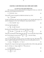
The following figure shows the flow of control to realize the order parts use case of
the IMS.
Interaction Diagram for the Order Parts Use Case
There are multiple slots in a collaboration, called roles, which are filled by objects and
links at run time. In other words, roles are used to depict the run-time responsibility of the
objects of a class and the relationship. The two types of roles in a collaboration are:
Classifier roles: Describe objects that can form a part of the collaboration.
Association roles: Describes the links that can form a part of the collaboration.
An interaction signifies the collection of communications that occur among the
classifier roles across the association roles. A collection of communications indicates
the messages that flow from one classifier role to another.
¤NIIT Understanding Dynamic Modeling 7.7
When an object calls the methods of another object, a sequence of messages flow between
them. The following table lists the various types of messages that can be sent from one
object to another and their graphical representation in an interaction diagram.
Message Description Graphical Representation
Call
Specifies the invocation of a method of
an object.
Return Returns a value to the calling method.
Send
Sends an asynchronous signal to an
object.
Create Creates an object.
Destroy Destroys an object.
The commonly used interaction diagrams are Sequence diagram and Communication
diagram. Let us, discuss how to create these diagrams.
Sequence diagrams represent an interaction among objects in the form of messages
ordered in a sequence by time. In a sequence diagram, you arrange objects across the
x-axis. You place the object that starts an interaction to the extreme left. The objects that
come later in the message sequence are placed to the right of the interaction-initiating
object. The messages sent and received by the objects in an interaction are placed along
the y-axis in an increasing order of time.
Creating Sequence Diagrams
7.8 Understanding Dynamic Modeling ¤NIIT
The following figure depicts the arrangement of objects and messages in a sequence
diagram.
Arrangement of Messages and Objects in a Sequence Diagram
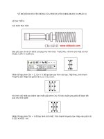
An object may be created or destroyed when an operation is performed. You can use
sequence diagrams to depict the creation and destruction of an object. In addition,
sequence diagrams depict the change in the focus of control of an object in the form of a
rectangular bar. The length of rectangle bar represents the duration of time for which an
object interacts with another object. The following figure depicts a sequence diagram that
shows how an object is created and destroyed, the focus of control, and the object lifeline.
Focus of Control and Object Lifeline in a Sequence Diagram
Object1
Ob
j
ect2
<<create>>
Message
<<destroy>>
Focus of
Control
Object
Lifeline
¤NIIT Understanding Dynamic Modeling 7.9
In the preceding figure, Object1 creates Object2 and subsequently sends a message to it.
When
Object2 completes its processing, it is destroyed.
Consider the following sequence diagram for the
Order Parts use case of the IMS
system.
Sequence Diagram for the Order Parts Use Case
In the preceding figure, the Inventory Manager creates an instance of the order class
and invokes the
issueOrder() method of the order class. The order object stores the
details in the
Inventory Database. When the details are stored in the database, the
order object receives a Transaction Complete signal and is then destroyed.
When an object invokes its own method or receives a callback from another object, a new
focus of control is represented over the existing focus of control and is called a nested
focus of control.
7.10 Understanding Dynamic Modeling ¤NIIT
N
ote
The following figure shows the nested focus of control of an object.
Nested Focus of Control
Unlike sequence diagrams, communication diagrams do not depict the object lifeline.
In a sequence diagram, the flow of control depicts a sequential flow of messages.
However, a programming logic may require you to depict the iterations of messages or the
branching of the flow of control. Iterations are repetitions of messages. You can use the
following statement to depict an iteration in a sequence diagram:
*[ j := 1 n ]
You use an asterisk, *, to indicate that the message is being sent repeatedly. You can
depict iteration by using the following notations:
[j < 10]: Specifies that the message will be sent until the value of j is less than 10.
[val not found]: Specifies that the message will be sent until val is found.
¤NIIT Understanding Dynamic Modeling 7.11
The following sequence diagram depicts that the Math object requests the
numberProperties object to calculate if a number is prime or not, iteratively.
Iteration in Sequence Diagrams
Branching of messages occurs when a set of messages responds to a call. The message to
be sent is guarded by a condition, which is a Boolean expression. If the condition
evaluates to true, then the first message is sent, otherwise, the second message is sent.
There is no specification on what type of conditions you may include in your interaction
diagrams. You can use either an English language expression or a programming language
expression. You can use the following English language expression to depict a condition:
[ j less than zero ]
The following statement shows how you can use a programming language expression to
write a condition:
[ j < = 0 ]
To depict the receipt of messages by an object, you can divide the object lifeline into
branches. The following figure shows how to divide an object lifeline into branches.
7.12 Understanding Dynamic Modeling ¤NIIT
N
ote
Branching the Object Lifeline
For example, in the IMS, the inventory manager checks the reorder level of an automobile
spare part before placing an order. If the reorder level condition is true, then the inventory
manager places the order for the spare part. If the reorder level condition is false, then the
inventory manager checks the information about the last order for the spare part.
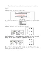
The following diagram depicts the branching of the flow of control of the
O1 object in the
Place Order use case of the order processing system.
The Sequence Diagram for the Order Parts Use Case
Messages in a sequence diagram may be sequenced by giving them a sequence number.
Messages can be given names that give a description of the message passing between
objects or can be mapped to a method of the called class.
Store Order Details
<<Create>>
[qty<=CritialLevel]
issueExpressOrder(pcode, scode)
issueOrder(pcode,scode)
checkQty()
p
1:
parts
Inventory
Database
o1:
order
[qty>CriticalLevel]
Transaction Complete
Store Order Details
Inventory Manager
¤NIIT Understanding Dynamic Modeling 7.13
N
ote
The guidelines that you need to follow when you model a sequence diagram are:
Identify the collaboration for an interaction in the system, subsystem, and use cases.
Identify the objects that have higher responsibility in the interaction. To draw a
sequence diagram, place the objects with high responsibility on one side and the low
responsibility objects on the other.
Identify the lifeline of each object in view of the control to depict the creation and
destruction of an object.
Identify the messages that flow between the lifeline of objects. You also need to
identify the properties of these messages to obtain information about the semantics of
the interaction.
Identify the preconditions and post conditions for each message to control the flow
of objects.
Communication diagrams represent the interaction among objects in the form of
messages. To draw a communication diagram, you identify the objects in collaboration
and represent them as the vertices of a graph. After you place the objects, you can draw
straight lines that represent the links among these objects to connect the objects. Note that
objects send and receive messages across these links. The dynamic aspect of an
interaction diagram can be depicted by messages that are passed among objects across
links. Therefore, communication diagrams depict the organization of objects in the
sequence of messages flowing between them. The constituents of a communication
diagram are organized in such a way that the related objects are closely placed. The
following figure shows a collaboration and the messages passed in the collaboration.
A Communication Diagram with Messages
Unlike communication diagrams, sequence diagrams do not have paths that link
objects and messages arranged according to time.
Creating Communication Diagrams
messageA
messageB
Collaboration of Objects
Ob
j
ect3
Ob
j
ect2
Ob
j
ect1
7.14 Understanding Dynamic Modeling ¤NIIT
N
ote
You can number the messages in a communication diagram for sequencing and indicating
their time order. The sequence numbers are prefixed before the messages. The following
figure shows the path between two objects and messages with sequence numbers in a
collaboration.
Path among Objects and Sequenced Messages in a Collaboration
The following figure shows the objects, links, and sequence of messages among the
various objects of the communication diagram for the use case, process order.
Communication Diagram with Sequenced Messages
Sequence and collaboration diagrams are isomorphic. This means that they contain the
same information and can be derived from each other. While sequence diagram depicts
the time sequencing of messages, the communication diagram depicts structural
responsibilities of the participating objects.
Sequence and communication diagrams are similar because of the fact that both represent
collaboration and the messages flowing between the constituents of the collaboration.
You can also depict iterations and conditions in a communication diagram in the same
way as in sequence diagrams. You can derive a communication diagram from a sequence
diagram by using the objects and messages of the sequence diagram. Organize the objects
so that the related objects are placed together and place a sequence number before each
¤NIIT Understanding Dynamic Modeling 7.15
message in the communication diagram based on the time ordering depicted in the
sequence diagram.
Similarly, you can derive a sequence diagram from a communication diagram by using
the objects and messages of the communication diagram. Place the objects and draw their
respective object lifelines. Draw the messages among objects according to the sequence
specified in the communication diagrams.
The guidelines that you need to follow when you model a communication diagram are:
Identify the collaboration that involves an interaction in the system, subsystem, and
use cases.
Identify the objects that have higher responsibility in the interaction. Draw these
objects on a graph so that the objects with high responsibility are placed on one side
and the objects with lower responsibility are placed on the other.
Identify the links among objects. You need to place the association links to depict the
relationship among objects.
Identify all the messages that flow across the links established among objects.
Assigning Responsibilities to Classes
You need to assign responsibilities to a class or a set of classes to ensure that the software
system has the required functions to suit the requirement document.
The decisions about responsibilities of classes are taken when interaction diagrams are
created. They include the decision to identify the methods that need to be invoked in one
object by another object so that each instance of a class carries out its responsibilities. A
responsibility is implemented by using methods of classes, which may implement the
entire responsibility or collaborate with the other methods to implement a responsibility.
Consider the IMS where you need to assign the responsibility of processing an order to a
class or multiple classes. The supplier class has the task to submit the order. The
submitOrder() method of the supplier class has the task to deliver the order. The order
class stores the information about the parts accepted and rejected. The order class accepts
and evaluates the order received from the supplier. The IMS database stores the
information about the order and the quantity of parts received and rejected. The three
collaborators for processing an order are
supplier class, order class, and inventory
database
.
7.16 Understanding Dynamic Modeling ¤NIIT
The following figure depicts the communication diagram with the objects carrying out
their responsibilities to process an order.
Communication Diagram with Class Responsibilities
The guidelines that you need to follow when you assign responsibilities to objects are:
Assign responsibilities to classes such that they perform all the tasks that are
performed by the real-world entity that the classes represent.
Assign responsibilities to a class if the class has the attributes that will enable it to
fulfill the responsibilities.
Assign responsibilities to multiple classes if all the classes have the data to fulfill the
responsibility.
Distribute responsibilities evenly to the various classes of your software system.
Check that all the classes of the software system have some responsibility assigned
to them. If no responsibility is assigned to a class, you need to check whether the
class is required.
Check if too many or unrelated responsibilities have been assigned to a class. If such
a class exists, split the class into smaller classes.
¤NIIT Understanding Dynamic Modeling 7.17
Just a minute:
Which of the following diagrams represents the interaction among objects in the form
of messages?
1. Composite structure diagram
2. Communication diagram
3. Timing diagram
4. Interaction Overview diagram
Answer:
2. Communication diagram
7.18 Understanding Dynamic Modeling ¤NIIT
Problem Statement
Janes Technology has been assigned the task of creating a dynamic model of the
prototype for the InfoSuper bank ATM system. Janes Technology needs to implement
only the cash withdrawal system in the prototype for the InfoSuper bank. The following
table describes the classes, attributes, and operations for the cash withdrawal feature of
the InfoSuper bank, which the design team of Janes Technology has identified.
Class Operations Description
ATM Show()
Displays the location and
branch name of the ATM.
GetPin()
Accepts the PIN entered by the
customer and verifies it.
GetAccount()
Fetches the account
information based on the
card_ID and PIN.
ATMCard
SetPin(int) Updates the PIN.
InsertCard()
Prompts the customer to insert
the ATM card.
SelectTransaction()
Selects a transaction from a
list of transactions.
EnterPin()
Prompts the customer to enter
the PIN.
ChangePin()
Invokes the PIN change
request. Enters the new PIN.
WithdrawCash()
Invokes the cash withdrawal
operation.
BankCustomer
RequestTransactionSummary()
Requests for a transaction
summary.
CalculateInterest()
Calculates the interest for the
account. This is an abstract
operation.
Account
UpdateAccount()
Updates the account
information.
Activity: Modeling the Dynamic View of the Bank
ATM System
¤NIIT Understanding Dynamic Modeling 7.19
Class Operations Description
VerifyWithdrawalAmount()
Verifies if the amount to be
withdrawn is less than the
account balance amount.
CurrentAccount CalculateInterest()
Calculates the interest for the
current account.
SavingsAccount CalculateInterest()
Calculates the interest for the
savings account.
GetAccountBalance()
Gets the balance of the
account.
StartTransaction() Initiates the transaction.
Transaction
CancelTransaction Cancels the transaction.
AcceptCard() Accept/rejects the ATM card.
ReadCard()
Reads the Card_ID associated
with the ATM card.
EjectCard() Ejects the ATM card.
CardScanner
ValidatePIN() Validates the pin number.
Prompt()
Prompts the respective screen
according to the request.
DisplayScreen
AcceptInput()
Accepts the required input on
the displayed screen.
SupplyCash()
Supplies the verified amount
as cash.
CashDispenser
GenerateReceipt()
Generates a receipt for the
cash dispensed.
7.20 Understanding Dynamic Modeling ¤NIIT
The design team has also created the following class diagram after identifying the classes
and operations for InfoSuper bank.
Class Diagram for the Prototype of the InfoSuper Bank ATM System
Identify the activities that the development team needs to perform to model the dynamic
view of the prototype.
Prerequisite: To perform this activity, you will need the BANK_ATM.vsd file, which
you created in the activity “Modeling the Static View of the Bank ATM System” of
Chapter 6.
¤NIIT Understanding Dynamic Modeling 7.21
Solution
To model the dynamic view of the cash withdrawal feature of the ATM system, you need
to perform the following tasks:
1. Identify the collaboration and interactions.
2. Create a sequence diagram.
3. Create a communication diagram.
Task 1: Identifying the Collaboration and Interactions
The following table lists the various classes that collaborate to realize the cash withdrawal
feature.
Class Responsibilities
BankCustomer Supply the PIN number.
Select the type of transaction.
Supply the amount to be withdrawn.
CardScanner Accept and read the card information.
Eject the card after the transaction is complete.
DisplayScreen Prompt the user for input.
ATMCard Verify the PIN number.
Get the information about the customer’s account.
Account Verify the PIN number.
Get the information about the customer’s account.
Verify the amount to be withdrawn.
Update the amount in the account after the transaction.
Transaction Starts a transaction.
Get the cash balance from the account.
CashDispenser Supply cash to the customer.
Generate a receipt of the transaction.
Class Responsibilities
7.22 Understanding Dynamic Modeling ¤NIIT
The following figure depicts the sequence diagram for the cash withdrawal feature of the
InfoSuper bank ATM system.
Sequence Diagram for the InfoSuper Bank ATM System
¤NIIT Understanding Dynamic Modeling 7.23
The following figure depicts the communication diagram for the cash withdrawal feature
of the InfoSuper bank ATM system.
Communication Diagram for the InfoSuper Bank ATM System
Task 2: Creating a Sequence Diagram
To create a sequence diagram, you need to perform the following steps:
1. Select StartÆAll ProgramsÆMicrosoft OfficeÆMicrosoft Office Visio for
Enterprise Architects.
2. Open the Bank_ATM Visio file. The Bank ATM model appears.
7.24 Understanding Dynamic Modeling ¤NIIT
3. Right-click the Iteration2 folder in the Model Explorer window, and select
NewÆSequence Diagram. The Sequence-1 tab with a blank drawing page appears.
4. Drag the Object Lifeline symbol (
) from the UML Sequence (Metric) stencil
on the drawing page.
5. Double-click the Object Lifeline symbol to set its properties. The UML Classifer
Role Properties dialog box appears.
6. Type CS in the Name text box.
7. Select Iteration2::CardScanner from the Classifier drop-down list, as shown in the
following figure.
UML Classifier Role Properties
¤NIIT Understanding Dynamic Modeling 7.25
8. Click the OK button. The following figure shows the object lifeline symbol for the
CardScanner class.
Object Lifeline Symbol for CardScanner Class
9. Right-click the Object Lifeline symbol and click the Shape Display Options option.
The UML Shape Display Options dialog box appears.
10. Select the Classifier name check box in General options section.
11. Click the OK button. The lifeline symbol appears as shown in the following figure.
Object Lifeline Symbol Displaying the Classifier Name
12. Similarly, draw the object lifeline symbols for the following classes:
z BankCustomer
z DisplayScreen
z ATMCard
z Account
z Transaction
z CashDispenser