Liquid Process Piping Episode 1 ppsx
Bạn đang xem bản rút gọn của tài liệu. Xem và tải ngay bản đầy đủ của tài liệu tại đây (177.18 KB, 18 trang )
CECW-ET 10 January 2003
Errata Sheet
No. 1
Engineering and Design
Liquid Process Piping
EM 1110-1-4008
5 May 1999
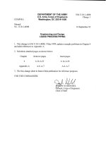
Reference to MSS SP-119 on page A-6, paragraph A-1 is in error. The title of the
document is incorrect. Page A-6, paragraph A-1: The title for MSS SP-119 should be as
follows: Belled End Socket Welding Fittings, Stainless Steel and Copper -Nickel.
CEMP-RA
Engineer Manual
1110-1-4008
Department of the Army
U.S. Army Corps of Engineers
Washington, DC 20314-1000
EM 1110-1-4008
5 May 1999
Engineer and Design
LIQUID PROCESS PIPING
Distribution Restriction Statement
Approved for public release; distribution is
unlimited.
EM 1110-1-4008
5 May 1999
US Army Corps
of Engineers
ENGINEERING AND DESIGN
Liquid Process Piping
ENGINEER MANUAL
AVAILABILITY
Electronic copies of this and other U.S. Army Corp of Engineers publications are available on the Internet at
This site is the only repository for all official USACE engineer regulations,
circulars, manuals, and other documents originating from HQUSACE. Publications are provided in portable document
format (PDF).
CEMP-RA
DEPARTMENT OF THE ARMY
U.S. Army Corps of Engineers
Washington, DC 20314-1000
EM 1110-l-4008
Manual
No. 1110-l-4008 5 May 1999
Engineering and Design
LIQUID PROCESS PIPING
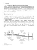
1.
The purpose of this manual is to provide information for the design of liquid process
piping.
2. Applicability. This manual applies to all HQUSACE elements and all USACE Commands
having responsibility for the design of unit processes for treatment of liquids.
3. Distribution Restriction. Approved for public release; distribution is unlimited.
4. References. References are provided in Appendix A.
5.
Scope. This manual is to be used in the selection of piping systems and materials for chemical
and physical unit processes. Process piping systems include pipe and appurtenances used to
transport fluids.
Separate guidance has been provided for plumbing, potable water, sewage, storm
drainage, fuel and lubricant systems.
6. Discussion. This manual includes criteria for the design of component parts and assemblies of
liquid process piping systems.
Compliance with these criteria requires that fundamental design
principles are followed. Modification or additions to existing systems solely for the purpose of
meeting criteria in this manual are not authorized.
FOR THE COMMANDER:
4 Appendices
(See Table of Contents)
Major General, U. S. Army
Chief of Staff
DEPARTMENT OF THE ARMY EM 1110-1-4008
U.S. Army Corps of Engineers
CEMP-RA Washington, DC 20314-1000
i
Manual
No. 1110-1-4008 5 May 1999
Engineering and Design
LIQUID PROCESS PIPING
TABLE OF CONTENTS
SUBJECT PARAGRAPH PAGE SUBJECT PARAGRAPH PAGE
Chapter 1
Introduction
Purpose 1-1 1-1
Applicability 1-2 1-1
References 1-3 1-1
Distribution 1-4 1-1
Scope 1-5 1-1
Metrics 1-6 1-1
Brand Names 1-7 1-1
Accompanying Guidance Stainless Steel 4-9 4-18
Specification 1-8 1-1
Manual Organization 1-9 1-3
Chapter 2
Design Strategy Chapter 5
Design Analyses 2-1 2-1
Specifications 2-2 2-1
Drawings 2-3 2-1
Bases of Design 2-4 2-2
Loading Conditions 2-5 2-7
Piping Layout 2-6 2-10
Chapter 3
General Piping Design
Materials of Construction 3-1 3-1
Design Pressure 3-2 3-2
Sizing 3-3 3-7
Stress Analysis 3-4 3-17
Flange, Gaskets and Bolting
Materials 3-5 3-19
Pipe Identification 3-6 3-23
Piping Supports 3-7 3-23
Testing and Flushing 3-8 3-29
Chapter 4
Metallic Piping Systems
General 4-1 4-1
Corrosion 4-2 4-1
Design Pressure 4-3 4-9
Piping Supports for Metallic
Piping Systems 4-4 4-9
Joining 4-5 4-12
Thermal Expansion 4-6 4-12
Ductile Iron 4-7 4-17
Carbon Steel 4-8 4-17
Nickel and Nickel Alloys 4-10 4-19
Aluminum 4-11 4-20
Copper 4-12 4-21
Plastic Piping Systems
General 5-1 5-1
Polyvinyl Chloride (PVC) 5-2 5-9
Polytetrafluoroethylene (PTFE) 5-3 5-9
Acrylonitrile-Butadiene-Styrene
(ABS) 5-4 5-9
Chlorinated Polyvinyl Chloride
(CPVC) 5-5 5-10
Polyethylene (PE) 5-6 5-10
Polypropylene (PP) 5-7 5-10
Polyvinylidene Fluoride (PVDF) 5-8 5-10
Chapter 6
Rubber and Elastomer Piping Systems
General 6-1 6-1
Design Factors 6-2 6-1
Sizing 6-3 6-4
Piping Support and Burial 6-4 6-5
Fluoroelastomer 6-5 6-5
Isobutylene Isoprene 6-6 6-5
Acrylonitrile Butadiene 6-7 6-5
Polychloroprene 6-8 6-5
Natural Rubber 6-9 6-5
EM 1110-1-4008
5 May 99
ii
TABLE OF CONTENTS - CONTINUED
SUBJECT PARAGRAPH PAGE SUBJECT PARAGRAPH PAGE
Chapter 7 Chapter 12
Thermoset Piping Systems Corrosion Protection
General 7-1 7-1
Reinforced Epoxies 7-2 7-5
Reinforced Polyesters 7-3 7-5
Reinforced Vinyl Esters 7-4 7-6
Reinforced Furans 7-5 7-6
Chapter 8 References
Double Containment Piping Systems
General 8-1 8-1
Piping System Sizing 8-2 8-6
Double Containment Piping
System Testing 8-3 8-7
Leak Detection Systems 8-4 8-8
Chapter 9 Appendix D
Lined Piping Systems Index
General 9-1 9-1
Plastic Lined Piping Systems 9-2 9-3
Other Lined Piping Systems 9-3 9-8
Chapter 10
Valves
General 10-1 10-1
Valve Types 10-2 10-9
Valve Sizing and Selection 10-3 10-13
Valve Schedule 10-4 10-20
Chapter 11
Ancillary Equipment
Flexible Couplings 11-1 11-1
Air and Vacuum Relief 11-2 11-1
Drains 11-3 11-5
Sample Ports 11-4 11-5
Pressure Relief Devices 11-5 11-5
Backflow Prevention 11-6 11-7
Static Mixers 11-7 11-8
Expansion Joints 11-8 11-9
Piping Insulation 11-9 11-10
Heat Tracing 11-10 11-12
Corrosion Protection 12-1 12-1
Cathodic Protection 12-2 12-1
Isolation Joints 12-3 12-2
Protective Coatings 12-4 12-4
Appendix A
Appendix B
Fluid/Material Matrix
Appendix C
Design Example
EM 1110-1-4008
5 May 99
iii
LIST OF TABLES
TABLE PAGE TABLE PAGE
1-1 Standard Pipe Dimensions 1-2
2-1 System Description 2-1
2-2 PFDs 2-2
2-3 P&IDs 2-2
2-4 Standards and Codes 2-5
2-5 Valve Location Design 2-15
2-6 Pump Connections Design 2-15
3-1 Pipe Material Roughness 6-3 General Chemical Compatibility
Coefficients 3-10
3-2 Estimated Pressure Drop for Elastomers 6-3
Thermoplastic Lined Fittings 6-4 RMA Oil and Gasoline Resistance
and Valves 3-12
3-3 Minor Loss Coefficients (K) 3-13
3-4 Gasket Compression 3-21
3-5 Gasket Factors and Seating Stress 3-23
3-6 Color Codes for Marking Pipe 3-25
3-7 Beam Coefficient (m) 3-26
3-8 Support Type Selection for Horizontal Resin Pipe 7-2
Attachments: Temperature Criteria 3-28
4-1 Galvanic Series 4-2
4-2 Environments Which Cause 7-4 Loop Leg Sizing Chart for Fibercast
Intergranular Corrosion in Sensitized RB-2530 Pipe 7-5
Austenitic Stainless Steels 4-6
4-3 Alloy/Susceptible Environment Combinations 8-3
Combinations for Stress-Corrosion 8-2 Common Orifice Coefficients 8-7
Cracking (Partial Listing) 4-7
4-4 Support Spacing for Steel Pipe 4-10
4-5 Support Spacing for Nickel Pipe 4-11
4-6 Support Spacing for Aluminum Systems (Lightly Oiled Bolting) 9-4
Pipe 4-12
4-7 Support Spacing for Copper Oiled Bolting) 9-4
Pipe 4-13
4-8 Applicable Codes for Metallic Fittings .4-14
5-1 Abbreviations for Thermoplastic 9-5 ANSI Class 300 Systems (Teflon-
Materials 5-1
5-2 Thermoplastic Joining Methods 5-3
5-3 Thermoplastic Joining Standards 5-3
5-4 Support Spacing for Schedule 80 9-8 Typical PVDF Liner Thickness
PVC Pipe 5-6
5-5 Support Spacing for Schedule 80 10-1 Recommended Flow
PVDF Pipe 5-6
5-6 Support Spacing for Schedule 80 10-2 Standard Control Valve Body
CPVC Pipe 5-7
5-7 Bedding Factor (K ) 5-7
x
5-8 Deflection Lag Factor (d ) 5-8
e
5-9 Values of EN Modulus of Soil Reaction
for Various Soils 5-8
5-10 Polyethylene Designations 5-11
6-1 Common Materials Used in Rubber/
Elastomer Piping Systems 6-1
6-2 Rubber and Elastomer Hose
Standards 6-2
Characteristics of Common
Classifications 6-3
6-5 Typical Hose Couplings 6-4
7-1 Thermoset Piping Systems
Standards (As of Nov. 1997) 7-2
7-2 Recommended Temperature Limits
for Reinforced Thermosetting
7-3 Support Spacing for Reinforced
Epoxy Pipe 7-3
8-1 Double Containment Piping Material
9-1 Thermoplastic Liner Temperature
Limits (Continuous Duty) 9-1
9-2 ANSI Class 125 and Class 150
9-3 ANSI Class 300 Systems (Lightly
9-4 ANSI Class 125 and Class 150
Systems (Teflon-Coated Bolting) 9-5
Coated Bolting) 9-5
9-6 Plastic Liner Material Properties 9-6
9-7 Liquid-Applied Coating Thickness 9-6
Required to Prevent Permeation 9-7
Characteristics 10-3
Materials 10-4
10-3 Wear and Galling Resistance Chart
of Material Combinations 10-5
EM 1110-1-4008
5 May 99
iv
LIST OF TABLES - CONTINUED
TABLE PAGE TABLE PAGE
10-4 Elastomer General Properties 10-6
10-5 Valve Seat Leakage Classifications 10-7
10-6 Class VI Seat Allowable Leakage 10-7
10-7 Valve Packing 10-8
10-8 Common Globe Valve Seating 10-12
10-9 Example Values of Valve Run F-G C-9
Capacity Factors 10-17
10-10 Valve Schedule 10-21
10-11 Valve Operator Schedule 10-22
11-1 Summary of Pressure Device Limits 11-6
11-2 Typical Reduced Pressure Backflow Stresses C-19
Prevention Assembly 11-8
11-3 Material Temperature Ranges 11-11
11-4 Typical Manufacturers' Data List 11-11
B-1 Fluid/Material Index B-2
C-1 Pollutant Concentrations C-1
C-2 Process Conditions, Design C-13 Line 80-IAS-1620 Supports C-27
Example Process Flow Diagram, C-14 Minor Losses for 40-SLG-1660 C-29
Continued C-3
C-3 Minor Losses for 80-INF-1500:
Run A-J C-8
C-4 Minor Losses for 80-INF-1500:
Run C-J C-8
C-5 Minor Losses for 80-INF-1500:
C-6 Flow Coefficient - Cv - Characterized
Seat Control Valves C-11
C-7 Line 80-INF-1500 Moments C-17
C-8 Line 80-INF-1500 Displacement
C-9 Line 80-INF-1500 Supports C-20
C-10 Line 80-IAS-1600 Supports C-21
C-11 Minor Losses for 80-IAS-1620 C-22
C-12 Line 80-IAS-1620 Displacement
Stresses C-26
C-15 Minor Losses for 25-PYS-101 C-34
C-16 Minor Losses for 40-FES-111 C-40
LIST OF FIGURES
FIGURE PAGE FIGURE PAGE
2-1 Process Flow Diagram (PFD) 2-3
2-2 Piping and Instrumentation 10-2 Control Valve Pressure Drop Curve 10-14
Diagram (P&ID) 2-4
2-3 Flexibility Arrangements 2-12
2-4 Remediation Process 10-5 Critical Pressure Ratios 10-19
Piping Plan 2-13
2-5 Isometric View 2-14
3-1 Moody Diagram 3-11
3-2 Pipe Supports for Ambient C-1 Design Example Process
Applications 3-29
4-1 Concentration-Cell Corrosion of C-2 Design Example Piping and
Underground Pipeline 4-5
8-1 Primary Piping Thermal C-3 Piping Layout Plan C-5
Expansion 8-4
8-2 Double Containment Piping Locations C-37
Expansion Loop Configuration 8-5
10-1 Valve Flow Characteristics 10-2
10-3 Control Valve Sizing 10-15
10-4 Valve Factor Diagram 10-18
11-1 Flexible Coupling 11-2
11-2 Pressure and Vacuum Breaker 11-4
12-1 Cathodic Protection Methods 12-3
Flow Diagram C-2
Instrumentation Diagram C-4
C-4 Piping Layout Plan with Support
EM 1110-1-4008
5 May 99
1-2
Table 1-1
Standard Pipe Dimensions
ANSI ISO
Nominal Pipe Size Actual D
(in) (in)
o
Nominal Pipe Size Actual D
o
(mm) (in) (mm) (in)
c 0.405 6 (0.236) 10 (0.394)
¼ 0.540 8 (0.315) 12 (0.472)
d 0.675 10 (0.394) 16 (0.630)
½ 0.840 15 (0.591) 20 (0.787)
¾ 1.050 20 (0.787) 25 (0.984)
1 1.315 25 (0.984) 32 (1.260)
1¼ 1.660 32 (1.260) 40 (1.575)
1½ 1.900 40 (1.575) 50 (1.969)
2 2.375 50 (1.969) 63 (2.480)
2½ 2.875 65 (2.559) 75 (2.953)
3 3.500 80 (3.150) 90 (3.543)
4 4.500 100 (3.937) 110 (4.331)
5 5.563 125 (4.921) 140 (5.512)
6 6.625 150 (5.906) 160 (6.299)
8 8.625 200 (7.874) 225 (8.858)
10 10.75 250 (9.843) 280 (11.024)
12 12.75 300 (11.81) 315 (12.402)
14 14.00 350 (13.78) 356 (14.00)
16 16.00 400 (15.75) 407 (16.00)
18 18.00 450 (17.72) 457 (18.00)
20 20.00 500 (19.69) 508 (20.00)
550 (21.65) 559 (22.00)
24 24.00 600 (23.62) 610 (24.02)
650 (25.59) 660 (25.98)
28 28.00 700 (27.56) 711 (27.99)
30 30.00 750 (29.53) 762 (30.00)
32 32.00 800 (31.50) 813 (32.00)
850 (33.46) 864 (34.02)
36 36.00 900 (35.43) 914 (35.98)
40 40.00 1000 (39.37) 1016 (40.00)
1050 (41.34) 1067 (42.00)
44 44.00 1100 (43.31) 1118 (44.00)
48 48.00 1200 (47.24) 1219 (48.00)
52 52.00 1300 (51.18) 1321 (52.00)
56 56.00 1400 (55.12) 1422 (56.00)
60 60.00 1500 (59.06) 1524 (60.00)
Note: D = Outer Diameter
o
EM 1110-1-4008
5 May 99
1-3
1-9. Manual Organization
Chapter 2 of this manual provides basic principles and
guidance for design. Chapter 3 presents engineering
calculations and requirements for all piping systems,
regardless of construction material. Subsequent chapters
address engineering requirements for specific materials
of construction, valves, ancillary equipment, and
corrosion protection.
a. Fluid/Material Matrix
Appendix B contains a matrix that compares pipeline
material suitability for different process applications.
Design for specific process applications should consider
temperature, pressure and carrier fluid. The use of
Appendix B is addressed in Chapter 3.
EM 1110-1-4008
5 May 99
2-2
instrumentation or other minor equipment, isolation
valves, vents, drains or safety devices unless operable in
a described mode. Table 2-2 lists the typical items
contained on a PFD, and Figure 2-1 depicts a small and
simplified PFD.
Table 2-2
PFDs
1. Major Equipment Symbols, Names, 4. All Process Piping, Sizes and Identification
Identification Number
2. Process Piping Vents, Drains, Special Fittings, Sampling
3. Control Valves and Other Valves that Affect
Operations 6. Direction of Flow
4. System Interconnections 7. Class Change
5. System Ratings and Operational Variables 8. Interconnections
maximum, average, minimum flow 9. Control Inputs/Outputs and Interlocks
maximum, average, minimum pressure
maximum, average, minimum temperature
6. Fluid Composition
c. Piping and Instrumentation Diagram (P&ID) environmental factors that are considered in the detailed
Content design of a liquid process piping system to ensure a
P&IDs schematically illustrate the functional relationship developed in order to perform design calculations and
of piping, instrumentation and system equipment prepare drawings.
components. P&IDs show all of the piping, including the
intended physical sequence of branches, reducers, and a. Predesign Surveys
valves, etc.; equipment; instrumentation and control
interlocks. The P&IDs are used to operate the process Predesign surveys are recommended for the design of
systems. Table 2-3 lists the typical items contained on a liquid process piping for new treatment processes and are
P&ID, and Figure 2-2 depicts a small and simplified a necessity for renovation or expansion of existing
P&ID. processes. A site visit provides an overview of the
d. Piping Sketches customer, an overall sense of the project is acquired, and
Major piping sketches may be included in a preliminary developed. For an existing facility, a predesign survey
design submittal. Sketches of the major piping systems can be used to evaluate piping material compatibility,
may be overlaid on preliminary equipment locations and confirm as-built drawings, establish connections, and
structural plans to indicate new pipe runs and provide develop requirements for aesthetics.
data input for a cost estimate.
Table 2-3
P&IDs
1. Mechanical Equipment, Names and Numbers
2. All Valves and Identification
3. Instrumentation and Designations
5. Miscellaneous Appurtenances including
Lines, Reducers and Increasers
2-4. Bases of Design
The bases of design are the physical and material
parameters; loading and service conditions; and
reasonable life cycle. The bases of design must be
project. Design requirements are obtained from the
an understanding of the aesthetics that may be involved is
EM 1110-1-4008
5 May 99
2-3
Figure 2-1. Process Flow Diagram (PFD)
(Source: SAIC, 1998.)
EM 1110-1-4008
5 May 99
2-4
Figure 2-2. Piping and Instrumentation Diagram (P&ID)
(Source: SAIC, 1998.)
EM 1110-1-4008
5 May 99
2-5
Soil conditions play a major role in the selection of piping These combinations are referred to as the service
systems. Soils which contain organic or carbonaceous conditions of the piping. Service conditions are used to
matter such as coke, coal or cinders, or soils set design stress limits and may be defined or specified by
contaminated with acid wastes, are highly corrosive. code, or are determined based on the system description,
These conditions impact ferrous metals more than site survey, and other design bases.
nonferrous metals. For normally acceptable metals, soil
variations may be significant. Buried pipes corrode faster c. Design Codes and Standards
at the junction line of dissimilar soils. In fact, electric
potentials up to one (1) volt may be generated by placing Standards, codes and specifications referenced
a metal pipe where it crosses dissimilar soils. throughout this document are issued by the organizations
Paragraph 12-2d addresses requirements for predesign based on project descriptions to determine and verify
surveys and soils sampling that may be necessary to applicability. This manual generally follows the
design cathodic protection systems. American Society of Mechanical Engineers (ASME)
b. Service Conditions minimum design requirements for various pressure
The piping system is designed to accommodate all comprehensive in including code requirements, it
combinations of loading situations (pressure changes, includes standards and recommendations for design of
temperature changes, thermal expansion/contraction and pressure piping.
other forces or moments) that may occur simultaneously.
listed in Table 2-4. Codes and standards are reviewed
Code for Pressure Piping, B31. ASME B31 includes the
piping applications. While this manual is not
Table 2-4
Standards and Codes
ANSI American National Standards Institute
11 West 42nd Street, New York, NY 10036
API American Petroleum Institute
1220 L Street NW, Washington, DC 20005
ASME The American Society of Mechanical Engineers
345 47th Street, New York, NY 10017
ASQC American Society for Quality Control
P. O. Box 3005, Milwaukee, WI 53201
ASTM American Society for Testing and Materials
100 Barr Harbor Drive, West Conshohocken, PA 19428
ISO International Organization for Standardization
1 Rue de Varembe, Geneva, Switzerland
MSS Manufacturer’s Standardization Society for the Valves and Fittings Industry
127 Park Street NE, Vienna, VA 22180
NIST National Institute of Standards and Technology Department of Commerce
Washington, D.C.
EM 1110-1-4008
5 May 99
2-6
Piping codes supply required design criteria. These manual, TM 5-811-7 (Army) and MIL-HDBK-1004/10
criteria are rules and regulations to follow when (Air Force), contain additional guidance pertaining to
designing a piping system. The following list is a sample cathodic protection of underground pipelines.
of some of the parameters which are addressed by design
criteria found in piping codes: Design concerns for the effects of physically damaging
- allowable stresses and stress limits; phenomena (for example, fires, spills, power outages,
- allowable dead loads and load limits; impacts/collisions, and breakdown or failure of associated
- allowable live loads and load limits; equipment) and natural phenomena (for example, seismic
- materials; occurrences, lightning strikes, wind, and floods). Risk is
- minimum wall thickness; a combination of probability and consequence. There are
- maximum deflection; infinite possibilities and all scenarios will not be covered
- seismic loads; and by direct reference to codes. Design experience must be
- thermal expansion. combined with a thorough evaluation of the likelihood of
Codes do not include components such as fittings, valves,
and meters. Design of these piping system components Working fluids carry abrasives that may wear internal
should follow industry standards. Standards supply surfaces. The accumulating damage may be impossible
required design criteria and rules for individual to observe until after system failure has occurred. The
components or classes of components, such as valves, most effective defense against this damage is to design
meters, and fittings. The purpose of standards is to protection into the system. Depending upon the process,
specify rules for each manufacturer of these components. monitoring pipe wall thicknesses may be necessary as an
This permits component interchangeability in a piping additive or alternate method to prevent failure due to
system. Standards apply to both dimensions and erosion.
performance of system components and are prescribed
when specifying construction of a piping system. It may not be practical in many cases to provide
d. Environmental Factors other overriding physical constraints. In these cases, the
The potential for damage due to corrosion must be components to allow for the effects of corrosion
addressed in the design of process piping. Physical occurring, over time. However, an understanding of a
damage may also occur due to credible operational and system’s environmental factors is required. For example,
natural phenomena, such as fires, earthquakes, high although it is generally true that thicker components will
winds, snow or ice loading, and subsidence. Two last longer in a corrosive situation, in a situation where
instances of temperature changes must be considered as severe pitting corrosion (see Paragraph 4-2 for
a minimum. First, there are diurnal and seasonal definitions and description of various types of corrosion)
changes. Second, thermal expansion where elevated is occurring thicker components may not last much longer
liquid temperatures are used must be accommodated. than those with standard thicknesses. In this case other
Compensation for the resulting expansions and design solutions are provided.
contractions are made in both the piping system and
support systems. Internal wear and erosion also pose The most common installation constraint is the need to
unseen hazards that can result in system failures. avoid interconnection of dissimilar metals. For example,
Chapter 4 discusses why corrosion occurs in metallic valves to carbon steel pipe. Short, easily replaced spools
piping, the problems that can result from corrosion, and may be considered for installation on both sides of such
how appropriate material choices can be made to components in order to protect the piping.
minimize corrosion impacts. All underground ferrous
piping must be cathodically protected. Chapter 12 of this
events fall into two broad categories: operational
all abnormal events.
corrosion-resistant materials due to structural needs or
most effective solution may be to design thicker
piping is often totally destroyed by connecting brass
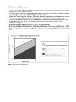
F
E
'
T
H
a
EM 1110-1-4008
5 May 99
2-7
e. Safety Provisions (1) For transient pressure conditions which exceed
Safety provisions as required by EM 385-1-1, The Safety less than 10 percent of the total operating time,
and Health Requirements Manual, USACE guide neglect the transient and do not increase the design
specifications, trade standards, codes, and other manuals pressure.
are referenced here. Requirements of the Occupational (2) For transients whose magnitude or duration is
Safety and Health Administration (OSHA) are minimum greater than 10 percent of the design pressure or
design constraints in USACE projects. operating time, increase the design pressure to
2-5. Loading Conditions
As described in Paragraph 2-4, the stresses on a piping pressure transients are addressed in Paragraph 3-2.
system define the service conditions of the piping system
and are a function of the loads on that system. The Dead weight is the dead load of a piping system or the
sources of these loads are internal pressure, piping weight of the pipe and system components. Dead weight
system dead weight, differential expansion due to generally does not include the weight of the system fluid.
temperature changes, wind loads, and snow or ice loads. The weight of the fluid is normally considered an
Loads on a piping system are classified as sustained or occasional load by code.
occasional loads.
a. Sustained Loads a sustained load that is analyzed is the load from the earth
Sustained loads are those loads that do not vary potential for deformation, the effects of an earth load on
considerably over time and are constantly acting on the flexible piping and rigid piping are analyzed differently.
system. Examples of sustained loads are the pressures, Paragraph 5-1 f addresses earth loads on buried flexible
both internal and external, acting on the system and the piping. The earth load on rigid piping may be calculated
weight of the system. The weight of the system includes using the following formula.
both that of the piping material and the operating fluid.
The sustained maximum system operating pressure is the
basis for the design pressure. The design temperature is
the liquid temperature at the design pressure. The
minimum wall thickness of the pipe and the piping where:
components pressure rating is determined by the design F = earth load, kPa (psi)
temperature and pressure. Although the design pressure T = soil weight, kg/m (lb/ft ); typically 1,922 kg/m
is not to be exceeded during normal, steady-state (120 lb/ft )
operations, short-term system pressure excursions in H = height of cover, m (ft)
excess of the design pressures occur. These excursions a = conversion factor, 102 kg/m /kPa (144
are acceptable if the pressure increase and the time lb/ft /psi).
durations are within code defined limits.
Piping codes provide design guidance and limits for
design pressure excursions. If a code does not have an Occasional loads are those loads that act on the system on
over-pressure allowance, transient conditions are an intermittent basis. Examples of occasional loads are
accounted for within the system design pressure. A those placed on the system from the hydrostatic leak test,
reasonable approach to over-pressure conditions for seismic loads, and other dynamic loads. Dynamic loads
applications without a specific design code is: are those from forces acting on the system, such as forces
the design pressure by 10 percent or less and act for
encompass the range of the transient.
The determination of design pressure and analysis of
For buried piping, dead weight is not a factor. However,
above the buried piping. Because of the different
1
E
3 3 3
3
2
2
b. Occasional Loads
AWWA C150, pp. 4-5.
1