Marine Machinery 7 E Part 1 ppsx
Bạn đang xem bản rút gọn của tài liệu. Xem và tải ngay bản đầy đủ của tài liệu tại đây (2.33 MB, 40 trang )
Marine Auxiliary Machinery
This page intentionally left blank
Marine
Auxiliary
Machinery
Seventh
edition
H. D.
McGeorge
C
Eng,
FIMarE,
MRINA,
MPhil
OXFORD
AMSTERDAM BOSTON LONDON
NEW
YORK PARIS
SAN
DIEGO
SAN
FRANCISCO
SINGAPORE
SYDNEY TOKYO
Butterworth-Heinemann
An
imprint
of
Elsevier Science
Linacre
House,
Jordan
Hill,
Oxford
OX2 8DP
225
Wild
wood Avenue, Woburn,
MA
01801-2041
First
published 1952 Reprinted
1976,1979
Second edition 1955 Sixth edition 1983
Third
edition 1963 Reprinted 1987
Fourth edition 1968 Seventh edition 1995
Reprinted
1971,1973
Paperback edition 1998
Fifth
edition 1975 Reprinted 1999, 2000
(twice),
2002
©
Copyright 1995, Elsevier Science Ltd.
All
rights reserved
No
part
of
this publication
may be
reproduced
in any
material
form
(including
photocopying
or
storing
in any
medium
by
electronic means
and
whether
or
not
transiently
or
incidental!
to
some other
use of
this publication) without
the
written permission
of the
copyright holder except
in
accordance with
the
provisions
of the
Copyright, Designs
and
Patents
Act
1988
or
under
the
terms
of
a
licence issued
by the
Copyright Licensing Agency Ltd,
90
Tottenham Court Road,
London, England
WIT
4LP. Applications
for the
copyright holder's written
permission
to
reproduce
any
part
of
this publication should
be
addressed
tit
the
publishers
British Library Cataloguing
in
Publication Data
Marine
Auxiliary Machinery
-
7
lh
rev.
edn
I.
McGeorge,
H.
David
0623.8
Library
of
Congress
Cataloguing
in
Publication Data
McCeorge,
H. D.
Marine
Auxiliary
Machinery/H.
D.
McGeorge
- 7
th
edn
Includes
bibliographical references
and
index
1.
Marine engines.
2.
Marine machinery
I.
Title
VM765.M38 1995
623.8'6—dc20
95-3360
CIP
ISBN
0
7506 4398
6
For
more information
on all
Butterworth-Heinemann publications
please
visit
our
website
at
www.bh.com
Typeset
by
Vision
Typesetting,
Manchester
Printed
and
bound
in
Great
Britain
by MPG
Books Ltd,
Bodrnin,
Cornwall
Contents
Preface
vil
Acknowledgements
ix
1
Main propulsion services
and
heat exchangers
1
2
Machinery service systems
and
equipment
40
3
Ship service
systems
78
4
Valves
and
pipelines
112
5
Pumps
and
pumping
139
6
Tanker
and gas
carrier cargo pumps
and
systems
176
7
Auxiliary power
214
8 The
propeller
shaft
245
9
Steering gears
286
10 Bow
thrasters,
stabilizers
and
stabilizing systems
314
11
Refrigeration
333
12
Heating, ventilation
and air
conditioning
368
13
Deck machinery
and
cargo
equipment
392
14
Fire
protection
418
15
Safety
and
safety
equipment
458
16
Control
and
instrumentation
480
Index
507
This page intentionally left blank
Preface
The
preparation
of the
seventh edition
of
this established book
on
marine
auxiliary
machinery
has
necessitated
the
removal
of
some
old
material
and the
inclusion
of new
topics
to
make
it
relevant
to the
present
day
certificate
of
competency examinations.
It is
hoped that
the
line drawings, many
of
which
were provided
by Mr R. C.
Dean,
a
former
colleague
in
London,
will
be
useful
for
the
certificate
of
competency
and
other examinations.
The
majority
of
other
illustrations
and
much
of the
basic text have been provided
over
the
years
by
the
various
firms
listed
in the
Acknowledgements.
I am
grateful
to
those
firms
who
have supplied
me
with material added
in
this edition.
H
D.
McGeorge
This page intentionally left blank
Acknowledgements
The
author
and
publishers would like
to
acknowledge
the
cooperation
of the
following
who
have assisted
in the
preparation
of the
book
by
supplying
information
and
illustrations,
Alfa-Laval
Ltd.
IMI-Bailey
Valves Ltd.
APE-Allen
Ltd.
IMO
Industri.
ASEA,
International Maritime Organisation.
Auto-Klean
Strainers Ltd.
KaMeWa.
Bell
&
Howell
Cons.
Electrodynamics. Richard
Klinger
Ltd.
Blakeborough
&
Sons Ltd.
Kockums
(Sweden).
Blohm
&
Voss A.G.
K.D.G.
Instruments Ltd.
Brown
Bros
& Co.
Ltd. Lister Blackstone Mirrlees Marine Ltd.
B.S.R.A.
Lloyds Register
of
Shipping.
Bureau
Veritas. Mather
&
Platt
Ltd.
Caird
&
Rayner Ltd. Metering Pumps Ltd.
Caterpillar Traction
Co.
Michell
Bearings Ltd.
Chubb
Fire
Security Ltd. Nash Engineering
(G.B.)
Ltd.
Clarke,
Chapman Ltd.
Navire
Cargo
Gear Int.
AB.
Cockburn-Rockwell
Ltd.
Norwinch.
Crane Packing Peabody Ltd.
W.
Crockatt
&
Sons Ltd. Penwalt Ltd.
R.
C.
Dean Peter Brotherhood Ltd.
Deep
Sea
Seals Ltd. Petters Ltd.
The
Distillers
Co. Ltd
(CO
2
Div.). Phillips Electrical Ltd.
Donkin
& Co.
Ltd. Thos. Reid
&
Sons (Paisley) Ltd.
Fire
Fighting Enterprises Ltd.
Ross-Turnbull
Ltd.
Fisher
Control Valves Ltd. Royles Ltd.
G. & M.
Firkins
Ltd. Ruston
Paxman
Diesels Ltd.
Foxboro-Yoxall Ltd. Simplex-Turbulo Marine Ltd.
G.E.C Elliott
Control Valves Ltd. Serck Heat Exchangers Ltd.
Germannischer
Lloyd. Spirax-Sarco Ltd.
Glacier Metal Ltd. Sofrance.
Hall
Thermotank
Ltd.
Sperry
Marine Systems Ltd.
The
Henri Kummerman Foundation
Stella-Meta
Filters
Ltd.
Howden Godfrey Ltd. Stone
Manganese
Marine Ltd.
Hamworthy
Engineering Ltd.
Stothert
&
Pitt Ltd.
Harland
&
Wolff
Ltd. Svanehoj, Denmark.
John
Hastie
& Co.
Ltd. Taylor
Servomax.
Hattersley Newman Hender Ltd. United Filters
&
Engineering Ltd.
Hawthorn Leslie (Engineers) Ltd. Vickers Ltd.
Hindle
Cockburns
Ltd. Vokes Ltd.
James
Howden
& Co.
Ltd. Vosper Ltd.
F.
A.
Hughes
& Co.
Ltd.
The
Walter
Kidde
Co.
Ltd.
W. C.
Holmes
& Co.
Ltd. Weir Pumps Ltd.
Howaldtswerke-Deutche
Werft A.G.
Welin
Davit
&
Engineering Ltd.
Hydraulics
&
Pneumatics Ltd.
Wilson-Elsan
Ltd.
Worthington-Simpson
Ltd.
This page intentionally left blank
1
Main propulsion services
and
heat exchangers
The
heat produced
by
running machinery, must
be
removed
to
ensure
the
satisfactory
functioning
of the
equipment.
Cooling
is
achieved
primarily
through circulation
of
water,
oil and air but the
abundant supply
of sea
water
is
normally
reserved
for use as an
indirect coolant because
the
dissolved salts
have
a
great potential
for
depositing scale
and
assisting
in the
setting
up of
galvanic corrosion cells. Pollution
of
coastal areas
by
industrial
and
other
wastes
has
added
to the
problems
of
using
sea
water
as a
coolant.
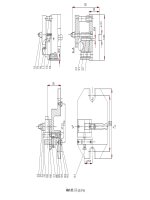
Circulating
systems
for
motorships
The
usual arrangement
for
motorships
(Figure
1.1)
has
been
to
have sea-water
circulation
of
coolers
for
lubricating oil,
piston
cooling,
jacket water,
charge
air,
turbo-charger
oil
(if
there
are
sleeve type bearings)
and
fuel
valve cooling, plus
direct sea-water
cooling
for air
compressors
and
evaporators.
The
supply
for
other auxiliaries
and
equipment
may be
derived
from
the
main sea-water
system also.
There
may be two
sea-water circulating pumps installed
as
main
and
stand-by units,
or
there
may be a
single sea-water circulating pump with
a
stand-by pump which
is
used
for
other duties.
The
latter
may be a
ballast pump
fitted
with
a
primer
and air
separator. Ship side valves,
can be
arranged
with
high
and low
suctions
or
fitted
to
water boxes. High suctions
are
intended
for
shallow water
to
reduce
the
intake
of
sediment.
Low
suctions
are
used
at
sea,
to
reduce
the
risk
of
drawing
in air and
losing suction when
the
ship
is
rolling.
A
water
box
should
be
constructed with
a
minimum distance
of 330 mm
between
the
valve
and the
top,
for
accumulation
of any air
which
is
then removed
by a
vent.
A
compressed
air or
steam connection
is
provided
for
clearing
any
weed.
Ship side
valve
bodies
for the
sea-water inlet must
be of
steel
or
other
ductile
metal.
Alternative materials
are
bronze, spheroidal graphite cast
iron,
meehanite
or
another high-quality cast iron. Ordinary grey cast iron
has
proved
to be
unreliable
and
likely
to
fail
should there
be
shock
from
an
impact
or
other
cause. Permissible cast irons must
be to
specification
and
obtained
from
an
approved
manufacturer.
Bronze
has
good
resistance
to
corrosion
but is
expensive
and
therefore tends
to be
used
for
smaller ship side valves. Steel
is
cheaper,
but
prone
to
corrosion,
It
may be
cast
or
fabricated. Unprotected steel valve casings
and
pipes
will,
in
Figure
1,1
Conventional sea-water circulation system
Main propulsion services
and
heat exchangers
3
the
presence
of sea
water
and
bronze
seats, valve lids
and
spindles, waste
due to
galvanic
corrosion. However,
the
presence
of
corroding iron
or
steel confers
benefits
in
sea-water systems.
The
metal acts
as a
sacrificial
anode
and
additionally
delivers iron ions which
are
carried through
and
give protection
to
other parts
of
system where they deposit.
The
fresh-water
circuit comprising
jacket
water circulating pumps,
fresh-water
coolers, cylinder jackets, cylinder heads, exhaust valves
(if fitted),
turbo-blowers
and
a
branch
to an
evaporator,
is
under positive
head,
and
therefore
in a
closed
system with
a
header tank.
It is
normal
for
there
to be a
blanked connection
between
the
sea-water system
and
engine jacket water circuit,
for use in an
emergency.
If the
engine
pistons
are
fresh-water
cooled,
the
circuit
may be in
parallel
with
the
jacket
circuit
but it is
more likely
to be
separate. Main
and
stand-by piston cooling water circulating pumps
are
mounted directly
on the
drain
tank
so
that with
flooded
suctions
no
primer
is
required.
The
piston
cooling system embraces
a
separate cooler,
the
inlet manifold, telescopic pipes,
pistons, outlet
manifold,
drain tank
and
pumps.
The
engine system temperatures
are
kept
as
high
as
practicable.
The
system
shown
has
salt-water bypass valves
on oil and
water coolers
for
temperature
control. These
are
valves controlled
by
thermo-pneumatic
devices.
It is
usual
to
make
provision
for
warming
the
fresh
circulating water before
the
main
engines
are
started,
either
by
steam
or by
circulating
from
the
auxiliary jacket
water
cooling
circuit.
The
auxiliary
sea-water cooling circuit
for
generator diesel prime movers
may
have
its own sea
inlet
and
pumps
for
circulation, with
a
cross connection
from
the
main sea-water circulation system.
Air
compressors
together
with
the
inter-
and
after-coolers
may be
supplied with sea-water cooling
in
parallel with
the
main system
or
alternatively, there
may be
crankshaft-driven pumps.
Charge
air
coolers
are
sea-water circulated.
The
jacket
water system
for
generator diesel prime movers
is
similar
to
that
for
the
main
engines, usually with
a
separate header tank. Pumps
for the
services
are
duplicated
or
cross
connected.
Sea-water pipes
for
circulation
of
cooling water, together with those
for
bilge
and
ballast
systems,
are
prone
to
internal wastage
from
corrosion
and
erosion. External corrosion
is
also
a
problem
in the
tank
top
area. Steel pipes
additionally
suffer
from
rusting.
Control
of
temperature
in
heat
exchangers
The
three basic methods
for
controlling
the
temperature
of the hot
fluid
in a
heat
exchanger
when
the
cooling
medium
is
sea-water, are:
1 to
bypass
a
proportion
or all of the hot fluid flow,
2
to
bypass
or
limit
the
sea-water
flow;
3 to
control sea-water temperature
by
spilling part
of the
sea-water
discharge
back
into
the
pump suction.
The
last
of
these methods could
be
used
in
conjunction with
one of the
other
4
Main propulsion services
and
heat exchangers
two and it was
resorted
to
when
sea
water
was
used
for
direct cooling
of
diesel
engines.
It
enabled
the sea
water
to be
passed through jackets
at a
temperature
warmer
than that
of the
sea. Very cold
sea
water would cause severe thermal
stress.
The
temperature
of sea
water
for
direct
cooling
was
kept
to
between
40°
and
49'
C, the
upper
limit
being necessary
to
limit
scale
formation.
Automatic
control equipment
for the
system shown above,
is
based
on
using
a
control valve
to
bypass
the sea
water
at the
outlet side
of the
heat
exchanger.
This
ensures
that
the
heat exchanger
is
always
full
of sea
water
and
is
particularly important
if the
heat exchanger
is
mounted high
in the
sea-water
system
and
especially
if it is
above
the
water line. Pneumatically operated
valves
may be fitted for
temperature control, through bypassing
the sea
water,
The
flow
of hot fluid
through
a
heat exchanger
may be
controlled
by a
similar
bypass
or by a
control valve
of the
Walton wax-operated type, directly
actuated
by a
temperature sensor.
Shell
and
tube coolers
Shell
and
tube heat exchangers
for
engine cooling water
and
lubricating
oil
cooling (Figure 1.2) have traditionally
been
circulated with
sea
water.
The sea
water
is in
contact with
the
inside
of the
tubes, tube plates
and
water boxes.
A
two-pass
flow is
shown
in the
diagram
but
straight
flow is
common
in
small
coolers.
The oil or
water being cooled
is in
contact with
the
outside
of the
tubes
and the
shell
of the
cooler.
Baffles
direct
the
liquid
across
the
tubes
as it flows
through
the
cooler.
The
baffles
also support
the
tubes
and
form
with them
a
structure which
is
referred
to as the
tube
stack.
The
usual method
of
securing
the
tubes
in
the
tube plates
is to
roll-expand them.
Tubes
of
aluminium
brass (76% copper;
22%
zinc;
2%
aluminium)
are
Figure
1.2
Tube
type
cooler
Main
propulsion
services
and
heat exchangers
5
commonly employed
and the
successful
use of
this material
has
apparently
depended
on the
presence
of a
protective
film of
iron ions, formed along
the
tube length,
by
corrosion
of
iron
in the
system. Unprotected iron
in
water
boxes
and in
parts
of the
pipe system, while
itself
corroding,
does
assist
in
prolonging tube
life.
This
factor
is
well known (Cotton
and
Scholes, 1972)
but
has
been made apparent when iron
and
steel
in
pipe systems have been
replaced
by
non-ferrous metals
or
shielded
by a
protective coating.
The
remedy
in
non-ferrous systems,
has
been
to
supply iron ions
from
other
sources. Thus,
soft
iron
sacrificial
anodes have been
fitted in
water boxes, iron
sections have been
inserted
in
pipe systems
and
iron
has
been introduced into
the sea
water,
in the
form
of
ferrous sulphate.
The
latter treatment consists
of
dosing
the sea
water
to a
strength
of 1 ppm for an
hour
per day for a few
weeks
and
subsequently dosing again before entering
and
after
leaving port
for a
short
period.
Electrical
continuity
in the
sea-water circulating pipework
is
important
where
sacrificial
anodes
are
installed. Metal connectors
are fitted
across
flanges
and
cooler sections where there
are
rubber joints
and
'O'
rings,
which
otherwise
insulate
the
various parts
of the
system.
Premature
tube
failure
can be the
result
of
pollution
in
coastal
waters
or
extreme
turbulence
due to
excessive sea-water
flow
rates.
To
avoid
the
impingement attack, care must
be
taken with
the
water velocity through tubes.
For
aluminium-brass,
the
upper
limit
is
about
2.5
m/s.
Although
it is
advisable
to
design
to a
lower
velocity than this
—
to
allow
for
poor
flow
control
- it is
equally
bad
practice
to
have sea-water speeds
of
less than
1
/sec.
A
more than
minimum
flow is
vital
to
produce moderate turbulence which
is
essential
to the
heat
exchange
process
and to
reduce silting
and
settlement
in the
tubes.
Naval
brass tube plates
are
used with aluminium-brass tubes.
The
tube stacks
are
made
up to
have
a fixed
tube plate
at one end and a
tube plate
at the
other
end
(Figure
1.3
)
which
is
free
to
move when
the
tubes expand
or
contract.
The
tube
stack
is
constructed
with
baffles
of the
disc
and
ring, single
or
double
segmental types.
The fixed end
tube plate
is
sandwiched between
the
shell
and
water
box, with jointing material, Synthetic rubber
'O'
rings
for the
sliding
tube
plate permit
free
expansion.
The
practice
of
removing
the
tube stack
and
replacing
it
after
rotation radially through
180
degrees,
is
facilitated
by the
Figure
1,3
Detail
of
cooler expansion arrangement
6
Main propulsion services
and
heat exchangers
type
of
cooler described. This
may
prolong cooler
life
by
reversing
the flow so
that tube entrances, which
are
prone
to
impingement damage, become outlets.
Cooler
end
covers
and
water boxes
are
commonly
of
cast iron
or
fabricated
from
mild steel. Unprotected cast iron
in
contact with
sea
water,
suffers
from
graphitization,
a
form
of
corrosion
in
which
the
iron
is
removed
and
only
the
soft
black graphite remains.
The
shell
is in
contact with
the
liquid being cooled which
may be
oil, distilled
or
fresh
water with corrosion inhibiting chemicals.
It may be of
cast iron
or
fabricated
from
steel. Manufacturers recommend that coolers
be
arranged
vertically.
Where horizontal installation
is
necessary,
the sea
water
should
enter
at the
bottom
and
leave
at the
top.
Air in the
cooler
system
will
encourage corrosion
and air
locks
will
reduce
the
cooling
area
and
cause
overheating.
Vent cocks should
be
fitted
for
purging
air and
cocks
or a
plug
are
required
at the
bottom,
for
draining.
Clearance
is
required
at the
cooler
fixed end for
removal
of the
tube
stack,
Plate type heat exchangers
The
obvious
feature
of
plate type heat exchangers,
is
that they
are
easily
opened
for
cleaning.
The
major
advantage over tube
type
coolers,
is
that their
higher
efficiency
is
reflected
in a
smaller size
for the
same cooling capacity.
They
are
made
up
from
an
assembly
of
identical metal pressings (Figure
1.4a)
with horizontal
or
chevron pattern corrugations; each with
a
nitrile
rubber joint.
The
plates, which
are
supported
beneath
and
located
at the top by
parallel
metal bars,
are
held
together
against
an end
plate
by
clamping bolts.
Four
branch pipes
on the end
plates, align with ports
in the
plates through
which
two fluids
pass. Seals around
the
ports
are so
arranged that
one
fluid
flows
in
alternate passages between plates
and the
second
fluid
in the
intervening
passages, usually
in
opposite directions.
The
plate corrugations promote turbulence (Figure 1.4b)
in the flow of
both
fluids and so
encourage
efficient
heat transfer. Turbulence
as
opposed
to
smooth
flow
causes more
of the
liquid passing between
the
plates
to
come into
contact
with them.
It
also breaks
up the
boundary layer
of
liquid
which tends
to
adhere
to the
metal
and act as a
heat barrier when
flow is
slow.
The
corrugations
make
the
plates
stiff
so
permitting
the use of
thin
material.
They
additionally
increase plate area. Both
of
these
factors
also contribute
to
heat
exchange
efficiency.
Excess
turbulence, which
can
result
in
erosion
of the
plate material,
is
avoided
by
using moderate
flow
rates. However,
the
surfaces
of
plates which
are
exposed
to sea
water
are
liable
to
corrosion/erosion
and
suitable materials
must
be
selected. Titanium plates although expensive, have
the
best resistance
to
corrosion/erosion. Stainless steel
has
also been used
and
other materials
such
as
aluminium-brass.
The
latter
may not be
ideal
for
vessels which operate
in
and out of
ports with polluted waters.
The
nitrile rubber seals
are
bonded
to the
plates with
a
suitable adhesive.
Removal
is
facilitated
with
the use of
liquid
nitrogen which
freezes,
makes
Main
propulsion
services
and
heat
exchangers
7
Figure
1.4a
Plate
type
heat
exchanger
Figure
1.4b
Turbulence
produced
by
plate
corrugations
brittle
and
causes contraction
of the
rubber seal which
is
then easily
broken
away.
Other
methods
of
seal removal result
in
plate damage.
Nitrile
rubber
is
suitable
for
temperatures
of up to
about
110°C.
At
higher
temperatures
the
rubber hardens
and
loses
its
elasticity.
The
joints
are
squeezed
when
the
plates
are
assembled
and
clamping bolts
are
tightened
after
cleaning.
8
Main propulsion services
and
heat exchangers
Overtightening
can
cause damage
to the
plates,
as can an
incorrect tightening
procedure.
A
torque spanner
can
be
used
as
directed when clamping
bolts
are
tightened;
cooler stack dimensions
can
also
be
checked.
Titanium
The
corrosion resistance
of
titanium
has
made
it a
valuable material
for use in
sea-water systems whether
for
static
or
fast
flow
conditions.
The
metal
is
light
weight (density
4.5
kg/m
3
)
and has
good
strength.
It has a
tolerance
to
fast
liquid
flow
which
is
better than that
of
cupro-nickel.
It is
also resistant
to
sulphide
pollution
in sea
water. While titanium
has
great corrosion resistance
because
it is
more noble than other metals used
in
marine systems,
it
does tend
to set up
galvanic cells with them.
The
less
noble
metals will
suffer
wastage
unless
the
possibility
is
reduced
by
careful
choice
of
compatible materials,
coating
of the
titanium, insulation
or the use of
cathodic protection,
Charge
air
coolers
The
charge
air
coolers
fitted
to
reduce
the
temperature
of air
after
the
turbo-charger
and
before entry
to the
diesel engine cylinder,
are
provided with
fins on the
heat transfer
surfaces
to
compensate
for the
relatively
poor
heat
transfer
properties
of
air. Solid drawn tubes with
a
semi-flattened cross section,
have
been favoured (Figure
1.5a).
These
are
threaded through
the
thin copper
fin
plates
and
bonded
to
them
with
solder
for
maximum heat transfer. Tube
ends
are fixed
into
the
tube plates (Figure 1.5b)
by
being expanded
and
soldered.
Cooling
of the air
results
in
precipitation
of
moisture which
is
removed
by
Figure
1.5a
Detail
of
charge
air
cooler tube arrangement
Main
propulsion services
and
heat exchangers
9
10
Main propulsion
services
and
heat exchangers
progressive increase
in the
temperature
difference
between
the two fluids, and
change
of
pressure.
Fouling
on the
sea-water side
is the
most usual cause
of
deterioration
in
performance.
The
method
of
cleaning
the
sea-water side surfaces depends
on
the
type
of
deposit
and
heat exchanger.
Soft
deposits
may be
removed
by
brushing.
Chemical cleaning
by
immersion
or in
situ,
is
recommended
for
stubborn
deposits. With shell
and
tube heat exchangers
the
removal
of the end
covers
or, in the
case
of the
smaller heat exchangers,
the
headers
themselves,
will
provide access
to the
tubes. Obstructions, dirt
and
scale
can
then
be
removed,
using
the
tools
provided
by the
heat
exchanger
manufacturer.
Flushing
through with
fresh
water
is
recommended before
a
heat exchanger
Is
returned
to
service.
In oil
coolers
or
heaters, progressive fouling
may
take place
on
the
outside
of the
tubes.
Manufacturers
may
recommend
a
chemical
flushing
to
remove this
in
situ, without dismantling
the
heat exchanger.
Plate heat exchangers
are
cleaned
by
unclamping
the
stack
of
plates
and
exposing
the
surfaces. Plate
surfaces
are
carefully
washed using
a
brush
or
dealt
with
as
recommended
by the
manufacturer
to
avoid
damage.
If the
plate seals
require
replacement they
may be
removed with
the
method described
in the
section
on
plate coolers. Prising
seals
from
their
bonding,
e.g. with sharp tools,
causes plate damage.
Corrosion
by sea
water
may
occasionally cause perforation
of
heat
transfer
surfaces
with resultant leakage
of one fluid
into
the
other. Normally
the sea
water
is
maintained
at a
lower pressure than
the
jacket water
and
other liquids
that
it
cools,
to
reduce
the risk of sea
water entry
to
engine spaces. Leakage
is
not
always
detected
initially
if
header
or
drain tanks
are
automatically
topped
up
or
manual
top up is not
reported. Substantial leaks become evident through
rapid
loss
of
lubricating
oil or
jacket water
and
operation
of low
level alarms.
The
location
of a
leak
in a
shell
and
tube cooler
is a
simple procedure.
The
heat
exchanger
is first
isolated
from
its
systems
and
after
draining
the sea
water
and
removing
the end
covers
or
headers
to
expose
the
tube plates
and
tube
ends,
an
inspection
is
made
for
evidence
of
liquid
flow or
seepage
from
around
tube
ends
or
from
perforations
in the
tubes.
The
location
of
small
leaks
is
aided
if
the
surfaces
are
clean
and
dry.
The
fixing
arrangement
for the
tube stack
should
be
checked before removing covers
or
headers
to
ensure that
the
liquid
inside
will
not
dislodge
the
stack. This precaution also underlines
the
need
for
isolation
of a
cooler
from
the
systems.
To aid the
detection
of
leaks
in a
large cooler such
as a
main condenser,
in
which
it is
difficult
to get the
tubes
dry
enough
to
witness
any
seepage,
it is
usual
to add a
special
fluorescent dye to the
shell side
of the
cooler. When
an
ultra-violet light
is
shone
on to the
tubes
and
tube plates leaks
are
made visible
because
the dye
glows.
Plate
heat exchanger leaks
can be
found
by
visual inspection
of the
plate
surfaces
or
they
are
cleaned
and
sprayed with
a fluorescent dye
penetrant
on
one
side.
The
other side
is
then viewed with
the aid of an
ultra-violet light
to
show
up any
defects.
Leaks
in
charge
air
coolers allow
sea
water
to
pass through
to the
engine
cylinder.
This
can be a
problem
in
four-stroke engines because there
is a
Main
propulsion services
and
heat exchangers
11
tendency
for
salt scale
to
form
on air
inlet valve spindles
and
this makes them
stick.
The
charge
air
manifold drain
is
regularly checked
for
salt water. Location
of
the
leak
may be
achieved
by
having
a
very
low
air
pressure
on the air
side
and
inspecting
the flooded
sea-water side
for air
bubbles. Soapy water could
be
used
as an
alternative
to
having
the
sea-water side flooded.
If
a
ship
is to be out of
service
for a
long
period,
it is
advisable
to
drain
the
sea-water side
of
heat exchangers
then
clean
and
flush
through with
fresh
water,
after
which
the
heat exchanger should
be
left
drained,
if
possible
until
the
ship re-enters service.
Venting
and
draining
It
is
important that
any
heat exchanger through which
sea
water
flows
should
run
full.
In
vertically-mounted single-pass heat exchangers
of the
shell-and-tube
or
plate types, venting
will
be
automatic
if the
sea-water
flow is
upwards. This
is
also
the
case with heat exchangers mounted
in the
horizontal attitude, with
single-
or
multi-pass tube arrangements, provided that
the
sea-water inlet
branch
faces
downwards
and the
outlet branch upwards. With these
arrangements,
the
water
will
drain
virtually completely
out of the
heat
exchanger when
the
remainder
of the
system
is
drained.
With other arrangements,
a
vent cock
fitted
at the
highest point
in the
heat
exchanger should
be
opened
when
first
introducing
sea
water into
the
heat
exchanger
and
thereafter periodically
to
ensure that
any air is
purged
and
that
the
sea-water side
is
full.
A
drain plug should
be
provided
at the
lowest point.
Heat exchange theory
The
rate
of flow of
heat
through
a
heat exchanger tube
or
plate
from
the fluid at
the
higher temperature
to the one at the
lower (Figure 1.6)
is
related
to the
temperature
difference
between
the two fluids, the
ability
of the
material
of the
tube
or
plate
to
conduct
and the
area
and
thickness
of the
material.
If
neither
fluid is
moving,
the
conductivity
of the fluids has
also
to be
taken
into
account
and the
fact
that with static conditions
as one fluid
loses
heat
and
the
other gains,
the
temperature
difference
is
reduced
and
this progressively
slows down
the
rate
of
heat
transfer.
With slow moving liquids
at
either side
of a
jacket cooler heat exchange
surface,
there
is
likely
to be a
constant temperature
difference
provided
the
hotter
fluid is
receiving heat
from
a
steady source
(as
from
a
cylinder water
jacket)
and
there
is a
continuous
source
for the
cooler
fluid
(circulation
from
the
sea).
Laminar
flow
(Figure 1.7) occurs
in
slow
moving
liquids with
the
highest
velocity
in the
centre
of the
liquid path
and a
gradually slower rate towards
containing
surfaces.
A
static boundary layer tends
to
form
on
containing
surfaces
and
heat
flow
through such
a
layer relies
on the
ability
of the
layer
to
conduct.
The
faster
moving layers also receive heat mainly
by
conductivity.
The
temperature
profile
across
an
element
of
wall
surface
may be
considered
12
Main propulsion services
and
heat exchangers
Figure
1.6
Temperature gradient between
fluids
Figure
1.7
Laminar flow
as
approximating
to
that depicted
in
Figure
1.6.
The
temperature
of the hot
fluid
falls
through
its
boundary layer
from
that
of the
bulk
of the fluid
(f
h
)
to
(f
hw
)
that
of the
wall. There
is a
further
drop through
the
wall
from
(f
hw
)
to
(f
w
)
and
then through
the
boundary layer
on the
cold side
from
(f
OT
)
to
(y
which
is
taken
as the
general temperature
of the
cold
fluid.
Considering
a
rate
of
heat
flow
<5Q
through
the
element
of
wall
surface
area
6A:
where:
/i^co-efficient
of
heat transfer
on the hot fluid
side;
h
2
=
co-efficient
of
heat transfer
on the
cold
fluid
side;
k
—
thermal conductivity
of the
wall
material;
y
=
thickness
of the
wall.
If
the
overall
co-efficient
of
heat
transfer
between
the hot and
cold
fluid is
defined
as:
Main propulsion services
and
heat exchangers
13
Figure
1.8
Effect
of
variation
in
cooling water flow
then
This
is the
basic equation
governing
the
performance
or a
heat exchanger
in
which
the
heat transfer
surface
is
completely clean. Additional terms
may be
added
to the right
hand side
of the
equation
to
represent
the
resistance
to
heat
flow
of films of
dirt, scale, etc.
The
values
of
h^
and
h
z
are
respectively deter-
mined
by the
fluids
and flow
conditions
on the two
sides
of
wall surface. Under
normal operating conditions, water
flowing
over
a
surface
gives
a
relatively
high
co-efficient
of
heat
transfer,
as
does
condensing steam, whereas
oil
provides
a
considerably lower value.
Air is
also
a
poor
heat transfer
fluid and it
is
quite usual
to
modify
the
effect
of
this
by
adding
extended
surface
(fins)
on
the
side
of the
wall
in
contact with
the
air.
In
a
practical
heat exchanger,
the
thermal performance
is
described
by the
equation.
where;
Q
—
rate
of
heat transfer;
B
=
logarithmic mean
of the
temperature
differences
at the
inlet
and
outlet
of the
heat exchanger: this
is a
maximum
if the fluids flow in
opposite directions
(counterflow);
A
=
surface
area
of
heat
transfer
wall.
It
is
sometimes important
to
appreciate
the
effect
of
variation
of
cooling
water
flow
through
a
heat exchanger.
The
graph
in
Figure
1.8
illustrates
two
typical
instances,
one a
jacket
water cooler
and the
other
a
lubricating
oil
cooler
(both
sea-water cooled),
in
which
the
difference
in
temperature between
the
hot fluid and the
sea-water
is
plotted against sea-water
flow,
assuming constant
hot fluid flow and
rate
of
heat
transfer.
14
Main propulsion services
and
heat exchangers
A dye can be
used
to
demonstrate laminar
flow In a
liquid
and
also
the
effect
of
speeding
up the flow
(Figure
1.9)
so
that turbulence
is
produced. Turbulence
is
an
agitation
of the
liquid caused
by
faster
flow. If a dye is
present when
the
flow
rate
is
increased,
the
agitation
is
made evident
in a
random movement
which
rapidly disperses
the
colouring substance. Turbulence
is
beneficial
in a
heat
exchanger,
because
it
rotates particles
of the
liquids
so
that they tend
to
break
up the
boundary layer
and
remove heat
by
direct contact with
the
heat
transfer
surfaces.
The
price
for the
benefit
of
turbulence
along
a
heat exchange
surface
is
that
at
tube entrances,
or the
entry area between
pairs
of
plates
in
plate
type coolers,
the
turbulence
is
more extreme
and
damage
from
corrosion/erosion occurs. This type
of
attack
is
termed impingement.
A
second advantage
of
turbulent
flow, is
that
the
scouring action tends
to
keep
cooler
surfaces
clean.
Central
cooling
system
The
corrosion
and
other problems associated with salt water circulation
systems
can be
minimized
by
using
it for
cooling central coolers through which
fresh
water
from
a
closed general cooling circuit
is
passed.
The
salt water passes
through
only
one set of
pumps, valves
and filters and a
short
length
of
piping.
Figure
1.10 shows
a
complete central cooling system
in
which
all
components
are
cooled
by
fresh
water.
The
three sections
are (1) the
sea-water
circuit;
(2) the
high temperature circuit;
and (3) the low
temperature circuit.
The
duty sea-water pump takes water
from
the
suctions
on
either side
of the
machinery space
and
after passing
through
the
cooler
it is
discharged straight
overboard.
The
main
and
stand-by pumps would
be of the
double entry
centrifugal
type but,
as an
alternative,
a
scoop arrangement
can be
incorporated (Figure
1.11)
with central
cooling.
A
main circulating pump must
have
a
direct
bilge
suction
for
emergency duty, with
a
diameter
not
less than
two
thirds that
of the
main sea-water inlet.
In
motor ships
a
direct suction
on
another pump
of the
same capacity
is
acceptable.
Materials
for the
reduced salt-water system
for the
central
cooling
arrangement
will
be of the
high quality needed
to
limit corrosion/erosion
problems.
Water
in the
high temperature
circuit,
is
circulated through
the
main
engine
and
auxiliary diesels
by the
pumps
to the
left
of the
engine
in the
sketch.
At the
outlet,
the
cooling water
is
taken
to the
fresh
water distiller (evaporator) where
the
heat
is
used
for the
evaporation
of sea
water. From
the
outlet
of the
Figure
1.9
Turbulent flow
of a
fluid