Hydroblasting and Coating of Steel Structures 2011 Part 9 pot
Bạn đang xem bản rút gọn của tài liệu. Xem và tải ngay bản đầy đủ của tài liệu tại đây (455.5 KB, 20 trang )
CHAPTER
6
Hydroblasting Standards
6.1
Introduction
6.2
Initial Conditions
6.3
6.4
Non-Visible Surface Cleanliness Definitions
6.5
Flash
Rusted Surface Definitions
6.6
Special Advice
Visual Surface Preparation Definitions and Cleaning Degrees
150
Hydroblasting and Coating
of
Steel Structures
6.1
Introduction
A
number of standards have been developed during recent years in order to define
and to characterise steel surfaces prepared by hydroblasting. These standards are
more or less based on the standard preparation grades given in IS0 8501-1
(uncoated parts of the surface), and
IS0
8501-2 (partial surface preparation). Two
types of standards can be distinguished, namely written standards and visual
standards.
0
Written standards:
-
SSPC-SP 12INACE No.
5:
‘Surface Preparation and Cleaning of Metals by
Visual standards issued
by
independent organisations:
-
STG Guide No. 222: ‘Definition of preparation grades for high-pressure
-
SSPC-VIS 4/NACE 7: ‘Guide and Reference Photographs for Steel Surfaces
-
US
Navy: ‘Process Guide for Waterjetting Operations in Navy Shipyards’.
Visual standards issued by paint manufacturers:
-
Hempel: ‘Photo Reference Water Jetting’ (1997).
-
International Paint: ‘Hydroblasting Standards’ (199
5).
-
Jotun: ‘Degrees
of
Flash Rusting
-
Guidelines for Visual Assessment of Flash
Waterjetting Prior to Recoating’
(1
99
5).
0
water-jetting’ (1992).
Prepared
by
Waterjetting’ (2001).
0
Rusting’ (1995).
Hydroblasting surface standards cover the following surface issues (see Fig. 6.1):
0
0
0
0
flash-rusted surface definition.
initial condition (rusty steel or primers);
visual surface preparation definition (visible contaminants, cleaning degrees):
non-visible surface cleanliness definition (basically salt levels):
Visual standards
Flash rusted
definition
Initial
Designation
rl
I_
Non-visible surface
Written standard
Figure
6.1
lssues
of
hydroblastinglwater jetting standards.
HMdrobZasting Standards
15
1
Table
6.1
Contents
of
hydroblastindwater
jetting
standards.
Standard
Surface reference for
Rusty Coating/ Flash Salt Cleaning
steel
primer rust level degree
SSPC-SP
12/NACE
NO.
5’
X
X
X
SPC-VIS
5/NACE
7
X
X
X
X
Hempel’s
Photo
Reference
X
X
X X
International Hydroblasting Standards
x
X
X
STG Guide
No.
2222
X
X X
Jotun Guidelines
on
Flash Rusting
X
’Written
standard.
Table 6.1 provides a general review of the content of the standards.
jetting standards are applied:
There are three very important points to be addressed
if
hydroblasting/water
(i)
(ii)
(iii)
The first point
is
that hydroblasted surfaces do not look the same as those
produced
by
dry abrasive blasting, or by slurry or wet blasting.
The second point is that visual standards should always be used in con-
junction with the written text, and should not be used as a substitute for
a
written standard.
The third point is that some of the standards are limited to certain sub-
strate materials. Hempel’s Water Jetting Standard states: ‘The steel is nor-
mal shipbuilding steel’. The SSPC-VIS 4/NACE
VIS
7
limits its range to
‘unpainted rusted carbon steel and painted carbon steel.’ Therefore, care
must be taken in applying these standards to other substrate materials.
6.2
Initial Conditions
Initial conditions are designated in several standards (see Table 6.1). These condi-
tions can be subdivided into two groups:
(i)
rusty steel
(C,
D);
(ii)
primers
or
coatings.
The initial steel grades
C
and
D
often characterise ‘new construction’ conditions; they
are adapted from
IS0
8501-1 (1988). They apply to uncoated steel surfaces that are
deteriorated due to severe corrosion. These rust grades are defined as follows:
0
steel grade
C:
‘Steel surface on which the
mill
scale has rusted away from which it can
be
scraped, but with slight pitting visible under normal vision.’ (see Fig. 6.4(a)).
‘Steel surface on which the mill scale has rusted away and on which general
pitting is visible under normal vision.’ (see Fig. 6.2(a)).
0
steel grade
D:
152
Hydroblasting and Coating of Steel Structures
(a) Rusty steel (rust grade
D;
below the rusty
layer a thin, almost black oxide layer is
adhering to
the steel).
(b) Old coating, consisting
of
several layers,
damaged on
top
sides,
DFT
300-370
pm.
w-,
Figure
6.2
Examples for initial conditions
of
a plain steel and a previously coated surface
(STG
2222).
Previously coated steel surfaces are characterised as ‘maintenance’ conditions.
There is a large number of possible systems and coating conditions. Cleaning results
do not depend on the intensity of cleaning only in these cases, but also essentially on
the type, thickness and adhesion of the coating systems, and on earlier surface
preparation steps. For these reasons, only analogous applications to real cases can
usually be derived. The coated steel surfaces considered in the hydroblasting stand-
ards include the following coating/primer systems and conditions:
0
0
0
0
0
paints applied over blast-cleaned surface; paints mostly intact (see Fig. 6.3(a));
painting systems applied over mill-scale bearing steel; systems thoroughly
weathered, thoroughly blistered or thoroughly stained;
degraded painting systems applied over steels (see Fig. 6.2(b));
multilayer systems with intercoat flaking and underrust;
shop primers with mechanical damage and white rust.
The most detailed descriptions of previously applied coatings can be found in STG
2222 (1992). This standard provides degree of rusting (Ri2 to Ri4) in accordance
with
IS0
4628-3 and
DIN
53210, and total film thickness of the paint systems.
6.3
Visual Surface Preparation Definitions and
Visible contaminants and cleaning degrees are defined in all standards except Jotun’s
Flash Rust Standard (see Table 6.1). Visible contaminants include the following:
Cleaning Degrees
0
rust;
0
previously existing coatings;
0
mill scale;
0
foreign matter.
Hydroblasting Standards
153
(a) Initial condition
E.
(c)
E
WJ-3.
(e)
E
WJ-2.
(b)
E
WJ-4.
(d)
E
WJ-3
(alternative).
(f)
E
WJ-1.
Figure
6.3
Examples for cleaning degrees (compare Table
6.3).
Previously painted steel surface: light-coloured
paint applied over blast-cleaned surface: paint mostly intact (SSPC-VlS 4INACE VlS
7).
Cleaning degrees are defined according to the presence of these matters. The high-
est cleaning degree always requires that the surface shall be free of all these matters,
and have a metal finish. The cleaning degrees designated in all standards are based
on the definitions given in
IS0
8501-1 for blast cleaned surfaces. Comparative clean-
ing degrees are listed in Table 6.2.
Of
particular interest are the definitions given in SSPC-l2/NACE No.
4
because they
are adapted by numerous other standards, and because the definitions provide a quan-
titative measure
of
surface cleanliness (in terms
of
limited percentage of adherent
foreign matter). These definitions are listed in Table 6.3.
A
typical surface preparation
specification for a coating system (Amercoat@
3
5
7,
Ameron International) reads as
154
Hydroblasting and Coating
of
Steel Structures
Table
6.2
Standard Cleaning degree
Comparative cleaning degrees (visible contaminants).
IS0
8501-1
Sa
1
Sa
2
Sa
2 112
Sa
3
SSPC
SP
7
SP
6
SP
10
SP
5
NACE
4
3
2
1
SSPGSP
12/NACE No.
5
WJ-4
WJ-3
WJ-2
WJ-1
Hempel’s Photo Reference
WJ-4 WJ-3 WJ-2
WJ-
1
International Hydroblasting Standard
-
HB2
HB
2
112
-
STG
Guide No.
2222
Dw
1
Dw
2
Dw
3
-
Table
6.3
Visible surface preparation standards (SSPC-l2/NACE No.
4).
Term Description
of
surface (when viewed without magnification)
~~ ~ ~~ ~~ ~ ~
WJ-1
Clean
to
bare substrate: the surface shall be cleaned to a finish which is free
of
all
visible rust, dirt, previous coatings, mill scale and foreign matter. Discoloration
of
the surface may
be
present.
WJ-2
WJ-3
Very thorough
or
substantial cleaning: the surface shall be cleaned
to
a
matte
(dull,
mottled) finish which is free of all visible oil, grease, dirt and rust except for randomly
dispersed stains of rust, tightly adherent thin coatings and other tightly adherent
foreign matter. The staining
or
tightly adherent matter is limited to a maximum
of
5%
of the surface.
Thorough cleaning: the surface shall be cleaned to a matte (dull, mottled) finish
which is free of all visible oil, grease, dirt and rust except for randomly dispersed
stains of rust, tightly adherent thin coatings and other tightly adherent foreign
matter. The staining
or
tightly adherent matter
is
limited to
a
maximum of
33%
of
the surface.
WJ-4
Light cleaning: the surface shall
be
cleaned to a finish which
is
free
of
all visible oil,
grease, dirt, dust,
lose
mill scale, loose rust and
loose
coating. Any residual material
shall be tightly adherent.
follows:
‘UHP
waterjeting per
SSPC-SP12/NACE No.5.
WJ-2L
or better is acceptable
for coated steel previously prepared to
SP-10
or better.’
(See
Table
6.3
for definition of
WJ-2.)
Examples of visual designations of the cleaning degrees listed in Table 6.3 are
provided in Fig.
6.3,
based on the removal
of
light-coloured paint applied over blast-
cleaned surface, and in Fig. 6.4, based on the preparation
of
a rusted surface. Paint
manufacturers recommend that, to ensure good adhesion, surfaces should be cleaned
to one
of
the grades higher than
WJ-4
(Kronborg,
1999).
6.4
Non-Visible
Surface
Cleanliness
Definitions
Problems associated with non-visible contaminants, in particular with soluble salts,
are discussed in detail in Section 5.4. Non-visible contaminants are considered
Hydroblasting Standards
1
5
5
Table
6.4
Definitions
for
non-visible surface cleanliness
(SSPC-SP lZ/NACE No.
5).
Term Description of surface
NV-1
Free of detectable levels
of
soluble contaminants, as verified by field or laboratory
Less
than
7
pg/cm2 of chloride contaminants, less than
10
pg/cmz
of
soluble
analysis using reliable. reproducible methods.
ferrous ion levels, or less than
17
p.g/cm2 of sulfate contaminants as verified by
field or laboratory analysis using reliable, reproducible test methods.
Less than
50
pg/cm2
of
chloride
or
sulphate contaminants as verified by field
or
laboratory analysis using reliable. reproducible test methods.
NV-2
NV-3
only in the written standard
SSPC-SP
12/NACE No.
5,
but are limited to water-
soluble chlorides, iron-soluble salts and sulphates. This standard distinguishes
between the three levels of non-visible contaminants listed in Table
6.4.
Other non-
visible contaminants, namely thin oil or grease Elms are not specified. None of the
visual standards defines non-visible contaminants simply because they cannot be
detected by the naked eye. However, some standards mention the ability of hydro-
blasting to remove salt, particularly from badly pitted and corroded steels. Paint
manufacturers usually
do
not specify non-visible contaminants because
of
the
problems outlined
in
Section 5.4.2. A rather typical demand reads as follows: ‘Prior
to coating, primed surface must be
.
free
of
all contaminants including salts.’
(Amercoat@
3
5
7,
Ameron International). Such vague specifications are difficult
to meet, and care must be taken to consult the paint manufacturer for a more
detailed information. Information about permissible salt levels is provided in
Tables
5.13
and
5.14.
6.5
Flash Rusted Surface Definitions
Problems associated with flash rust are discussed in detail in Section 5.3. Degrees of
flash rusting are defined in several standards (see Table 6.1). Basically, the temporal
development of rusting is considered, and flash rusting degrees are defined and dis-
tinguished according to the following criteria:
(i)
(ii)
(iii)
colour of the rust layer (e.g., ‘yellow-brown rust layer’):
visibility of the original steel surface (e.g., ‘hides the original surface’):
adherence
of
the rust layer (e.g., ‘loosely adherent’).
In the early stage of flash rusting
(FR-1,
L,
JG-2), the rust layer is usually of a
brown colour; the original steel surface
is
partially discoloured; the rust is tightly
adhering.
In
the latest stage of flash rusting
(FR-3,
H,
JG-4), the colour turns
to
red:
the original steel surface is hidden: the rust is loosely adhering. The tape method
according to Hempel’s Water Jetting Standard, that can be used to quantify flash rust
degrees, is already described in Section 5.4 (see also Fig. 6.4). Other simple, and only
156
Hydroblasting and Coating
of
Steel Structures
qualitative methods are listed in Table 6.5. It can be seen that a rough estimate of
heavy flash rust is its capability to significantly mark ‘objects’ (cloth, dry hand)
brushed against or wiped over it.
A
typical specification statement for a coating
system (Hempadur 4514, Hempel Paints) applied to flash rusted surfaces reads as
follows:
fA
flush
rust of FR-2 for atmospheric conditions, and FR-2 (preferably FR-1)
for water conditions, respectively, is acceptable prior to coating.’ Examples of visual
designations
of
the flash rust definitions listed in Table 6.6 are provided in Fig. 6.4,
based
on
the surface preparation of rusted steel surfaces.
Methods for the removal of flash rust that is too heavy for coating applications are
recommended in several standards. These methods include brushing (for small
areas) and washing down with pressurised (pressure above
7
MPa) fresh water.
Although pressure washing causes the surfacc to re-rust, it
is
possible to reduce the
degree of flash rust from heavy to light.
Table
6.5
Approximate methods
for
estimating heavy flash
rust
adhesion.
Standard
International Hydroblasting
Standard
(H)
VIS
7
(H)
SSPC-VIS 4/NACE
Hempel Photo Reference
Water Jetting (FR-3)
Method
for
estimating heavy flash rust adhesion
This layer
of
rust will be loosely adherent and will easily mark
The rust is loosely adherent, and leaves significant marks on a
The rust is loosely adhering and will leave significant marks on
objects
brushed against it.
cloth
that
is
lightly wiped ovcr the surface.
a
dry hand,
which is swept over the surface with
a
gentle pressure.
Table
6.6
Flash
rust
surface definitions
(SSPGSP
12lNACE No.
5).
Term
Description
of
surface (when viewed without magnification)
No
flash rust
A
steel surface which exhibits no visible flash rust.
Light
(L)’
others:
Slight
(JG-2)2
(~~-113
Moderate
(M)l
others:
Moderate (JG-3)2
(m-2)3
A
surface which exhibits small quantities
of
a
yellow-brown rust layer
through which the steel substrate may be observed. The rust
or
discoloration may be evenly distributed
or
present in patches, but it is
tightly adherent and
not
easily removed by lightly wiping with a cloth.
A
surface which exhibits a layer
of
yellow-brown rust that obscures the
original steel surface. The rust layer may be evenly distributed
or
present
in patches, but it is reasonably well adherent and leaves light marks on
a
cloth that is lightly wiped over the surface.
Heavy
(H)I
others:
A
surface which exhibits
a
layer
of
heavy red-brown rust that hides the
initial surface condition completely. The rust may
be
evenly
distributed
or
present in patches, but the rust is loosely adherent,
easily comes
of
and leaves significant marks on a cloth that
is
lightly
wiped over the surface.
Considerable
(JG-4)2
(FR-3)3
‘Equivalent definition in International Hydroblasting Standards.
’Designation according to Jotun.
3Designation according to Hempel.
Hydroblasting Standards
15
7
(a) Initial condition:
C.
(b)
C
WJ-2
FR-1
22
23
24
25
28
27
28
29
31
I
(d)
C
WJ-2
FR-3.
Figure
6.4
Reference Water Jetting).
Visualpush rust designations (compare Tables
6.5
and
6.6);
rusty steel: rust grade
C
(Hempel
Photo
6.6
Special Advices
Hydroblasting/water jetting standards all contain sections with special advice which
should be read with care. These include the following:
0
0
0
0
0
Time of surface assessment.
Procedures for using standards (especially photographs):
Inspecting areas of difficult access (e.g. backs
of
stiffening bars):
Inspecting blasted surfaces prior to flash rusting:
Limitations to hydroblasting (e.g. the removal of oil and grease, or milscale);
CHAPTER
7
Alternative Developments
in
Hydroblasting
7.1
Pulsed Liquid Jets for Surface Preparation
7.1.1
Types
and Formation of Pulsed Jets
7.1.2 Surface Preparation with Cavitating Water Jets
7.1.3 Surface Preparation with Ultrasonically Modulated Water Jets
7.1.4 Surface Preparation with Self-Resonating Water Jets
7.2 Hydro-Abrasive Jets for Surface Preparation
7.2.1 Types and Formation
of
Hydro-Abrasive Jets
7.2.2 Alternative Abrasive Mixing Principles
7.2.3 Surface Preparation with Hydro-Abrasive Jets
7.2.4 Surface Preparation by Ultra-High Pressure Abrasive Blasting
7.3 High-speed Ice Jets for Surface Preparation
7.3.1 Types and Formation of High-speed Ice Jets
7.3.2 Surface Preparation with High-speed Ice Jets
7.3.3 Caustic Stripping and Ice Jetting
7.4
Water Jet/Ultrasonic Device for Surface Preparation
160
Hydroblasting and Coating
of
Steel Structures
7.1
Pulsed Liquid Jets
for
Surface Preparation
7.1.1
Types and Formation
of
Pulsed
lets
It has been shown in the previous Chapters that any impacting water jet exhibits two
pressure levels: an impact pressure in the very early stage of jet impact
(h),
and a
stagnation pressure
(
pST)
that is established after the impact period. The impact pres-
sure is given through
Eq.
(2.23). the stagnation pressure can be estimated based on
Bernoulli's law:
The ratio between these pressure levels depends on the jet velocity and can be
estimated from
ps
=
as follows:
(7.2)
This relationship is illustrated in Fig. 7.1 in terms of operating pressures. The pressure
ratio equals the value
RP
=
1
for
vJ
=
2
-
cF.
The corresponding operation pressure
would be p
z
4
*
lo3
MPa. This high value cannot be realised
by
commercial plunger
pumps
or
pressure intensifiers. For a rather low pressure, say 30 MPa, the pressure
ratio is about
RP
=
11
(see Fig.
7.1).
It was shown in Section 2.4.2 that erosion
efficiency increases as operating pressure increases. This relationship challenges the
use of mechanisms able to produce high-speed fluid slugs. Basically, the following
two
types
of pulsed water jets can be distinguished (see Fig. 7.2):
0
0
low-frequency water jets
(
fp
=
1
kEk);
high-frequency water jets
(
fp
>
5
kHz).
0
20
40
60
Operating pressure
in
MPa
Figure
7.2
Pressure mtio during jet impact.
Alternative Developments in Hydroblasting
161
Cavitating jets
4
Self-resonating jets
1
Figure
7.2
Subdivision
of
pulsating jets.
Both techniques involve the modulation of continuous high-speed water jets. The
difference to ‘naturally pulsed jets’ (formed due to aero-dynamic drag, see Fig.
2.6)
is that the jets are artificially interrupted. Pulsed jets can be produced in several ways
using different driving energy sources. When considering the use of pulsed jet
devices, the following criteria should be kept in mind:
0
size and weight;
0
ease of manufacture;
0
cost effectiveness:
0
mobility;
0
reproducibility of cleaning results;
0
reliability under site conditions;
0
safety.
Therefore, only a few technical solutions, although more were successfully applied
under laboratory conditions, can currently be used under site conditions: they
include the following:
0
cavitating jets;
0
ultrasonically modulated jets;
0
self-resonating jets.
Technical fundamentals as well as applications of these types of pulsating jets to
surface cleaning will be discussed in the subsequent sections. Low-frequency pulsat-
ing water jets, such as water cannons, are frequently applied to break and fracture
massive solids, but they are not suitable for decoating and paint stripping; see
Momber (1998a) for more details about this technique.
The
two
most important parameters
of
pulsed liquid jets are loading intensity and
loading frequency. For some pulsed liquid jet concepts water jet velocity and pulse
frequency cannot be varied independently from each other. Both parameters must
be selected according to the materia1 to be eroded. Materials
usually
called ductile
may require high-frequency loading, whereas materials usually considered brittle
may be more sensitive to a longer loading period. Loading intensity is basically a
function of jet velocity. Frequency, however, depends on the mechanism used to form
the pulsating jet.
162
Hydroblasting and Coating
of
Steel Structures
7.1.2
Surface Preparation with Cavitating Water Jets
It was proved that cavitation erosion is a very promising method for efficient coating
removal (Kaye
et
aZ.,
1995). Cavitation is defined as the formation, growth and
collapse of vapour filled cavities in liquid flow. The cavity bubbles begin as tiny undis-
solved gas nuclei in the liquid. Subsequent to their formation and growth in the
localised regions of higher local pressure, the cavities are carried by the flow into the
regions
of
higher local pressure where they collapse. Detailed descriptions of cavita-
tion phenomena are provided in the standard literature (Knapp
et
aZ.,
19 70; Lecoffre,
1999). Cavitation can damage and erode materials by the following mechanisms:
0
0
0
generation of shock waves due to symmetric bubble implosion;
formation of micro-jets due to non-symmetric bubble implosion (Lauterborn
and Bolle, 1975), see Fig. 7.3);
collapse of bubble clusters (Dear and Field, 1988).
Figure
7.3
Giittingen).
Micro-jet formation during non-symmetric
bubble
implosion (photograph: Lauterborn,
Univ.
Alternative Developments in Hydroblasting
163
However, a superposition of several individual mechanisms is very likely The pres-
sure
generated during the implosion and collapse of cavitation bubbles
is
typically in
the range of several
1
O2
MPa. Conn
(
19
72) provides an analysis of the collapse pres-
sure of vapour bubbles cavitating in the region where a fluid jet impacts a material
surface. This pressure
is
given by
The equation illustrates the influence of the gas content in the jet on the collapse pres-
sure.
A
graphical solution of
Eq.
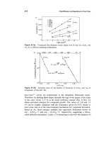
(7.3)
for different gas content is provided in Fig. 7.4
(the stagnation pressure is replaced by the jet velocity).
This
graph
also
shows that
collapse pressures exceed even the impact pressure developed during the impact
of
a
fluid slug by an order of magnitude.
A
pressure ratio,
Ri,
can again be defined to eval-
uate the effectiveness of cavitating water jets:
(7.4)
Values for the pressure ratio can be as high as
R;
=
32
as shown in
Fig.
7.4.
However, concrete values depend
on
gas content and bubble size (Houlston and
Vickers,
19
78).
Fouling removal tests with cavitating water jets and self-resonating water jets
were performed by Conn and Rudy
(1978);
the results are listed in Table
7.1.
The
cleaning rates are rather high compared to values
known
from standard hydroblast-
ing applications.
16
I
12
-
0
200
400
600
800
1000
Jet
velocity
in
m/s
Figure
7.4
Collapse pressures in cavitating water jets.
164
Hydroblasting and Coating of Steel Structures
Table
7.1
Cleaning efficiency
of
cavitating water jets (Conn and Rudy,
1978).
Nozzle configuration Cleaning rate
in
m2/h'
Specific energy in
m2/kWh'
IX
6.4
mm
1
X
3.2
mm
6
X
3.0
mm
44.5
16.7
167
0.90
1.52
-
Epoxy
coated steel panels.
Figure
7.5
Structure of an ultrasonically modulated water jet (photograph:
VLN
Advanced Technologies lnc.).
Figure
7.6
Technologies Inc.).
On-site device for the formation of ultrasonically modulated jets (photograph:
VLN
Advanced
7.1.3
Surface Preparation with Ultrasonically Modulated Water Jets
Ultrasonic waves generated within
a
nozzle can be employed to modulate a continu-
ous stream
of
water to produce either pulsed or cavitating jets (see Vijay
et
al.,
1993).
The structure
of
a water jet modulated by this technique is illustrated in Fig.
7.5.
An on-site device for the generation
of
ultrasonically modulated water jets is shown
in Fig.
7.6.
The entire system consists
of
a pump, an ultrasonic power generator with
Alternative Develnpments in Hydroblasting
16
5
a converter, a high-pressure dump gun, a high-pressure hose and numerous acces-
sories. The pump delivers
a
volumetric flow rate of
22.7
I/min at
a
maximum operat-
ing pressure of
41.4
MPa. The ultrasonic power generator has a capacity of
1.5
kW of output at a resonant frequency of
fp
=
20
kHz.
Coating removal tests
performed on ships with this equipment showed the following (Vijay
et
RZ.,
1999):
0
0
0
0
0
0
the machine's overall size
(0.787
m
X
0.838
m
X
1.4
m) made it ideal
for
use
on ships:
as the weight was well balanced, it could be manoeuvred about the ship with
relative ease:
rubber casters, with swivels and locking features, were found to be durable to
withstand the weight and vibrations of the machine:
control panel buttons were robust to withstand rough handling in industrial
setting:
moisture in the electrical plug was a problem for the faulty operation
of
the
ultrasonic unit:
wide variations in the temperature did not affect the performance
of
the ultra-
sonic unit.
The certain material removal mode depends mainly on coating structure. On brit-
tle coatings, at operating pressures of
7
MPa, the corresponding impact pressure
(1
60
MPa) forms a hemispherical crack on the layer. With further impacts, the crack
propagates radially through the layers to the Iayer/primer interface. This stream
of
water then enters these cracks and peels off the coating layer by Iayer. For higher
operating pressures, the adhesive forces between substrate and primer may be
exceeded by the impacting fluid slug. These mechanisms are described in detail by
Vijay
et
al.
(1997).
Results from coating removal tests performed with this technique are displayed in
Fig.
7.7.
It is shown that modulated jets can remove coating systems with pressures
4
p=34.5
MPa,
x
=
127
mm
4
Traverse rate
in dmin
120
no paint
or
primer
removed
by
continous
jet
.E
60
-
:
fp=lkw
0
"""""'
0
10
20
30
Impact angle in
O
Figure
7.7
water jets (Vijay
et
al
1997).
Parameter injlrtence (traverse rate (a) and impact angle
(1)))
on
coating removal with modulated
166
Hydroblasting and Coating
of
Steel Structures
1.2
p
=
34.5
MPa
m
x=127mm
fp
=
15
kH2
X
m
Pp=
1
kW
c
._
F
E
0.4
0
0
0
'' "*''*
0
1
2
3
4
0
5
10
15
20
Traverse rate
in
mlmin
Impact
angle in
Figure
7.8
Specific energyfor coating removal with modulated wafer jets (Vijay
et
al.,
1997).
much lower than the corresponding pressures of continuous water jets. Certain
coating systems can be stripped with modulated jets only in the given pressure
range. Figure 7.7(a) shows that a definite traverse rate of the nozzle carrier exists
for maximum coating removal efficiency. This optimum traverse rate decreases
if
operating pressure increases. Note from Fig. 7.8(a) the minimum in the specific
energy is
in
the range of medium traverse rates. Modulated jet should be applied at
perpendicular angles: this is illustrated in Figs. 7.7(b) and 7.8(b). Maximum erosion
occurs at an angle of
9
=
go",
whereas no erosion takes place with a jet inclined at
an angle of
4
=
30".
As
expected, specific energy increases
if
impact angle deviates
from 90". Typical removal rates for a non-skid coating are
up
to
4.5
m2/h: the cer-
tain value depends on traverse rate and stand-off distance. An optimum stand-off
distance is
xo
=
25
mm in many cases (Vijay
et
aI.,
1999).
7.1.4
Surface Preparation
with
Serf-Resonating Water Jets
Self-resonating pulsating jets are formed by running a jet flow through a specially
designed nozzle; acoustic resonance effects force the vibration and disintegration of
the jet. This principle was first noted with air jets (Crow and Champagne, 1971;
Morel, 19 79). Several self-resonating nozzle system concepts can be distinguished.
They are described in detail in the original literature (Johnson
et
al.,
1984; Chahine
et
d.,
1985).
A
non-dimensional parameter which defines the periodic characteris-
tic of self-resonating jets is the Strouhal number, given through:
This number combines acoustic and aerodynamic parameters. It is known that
optimum performance of pulsating water jets occurs for Strouhal numbers between
Alternative Developments in Hydroblasting
167
Figure
7.9
Appearance
of
a self-resonating water jet, v,
=
83.8
mls,
fp
=
4.6
kHz
(photograph: Dynaflow@ lnc.,
Jessup).
Figure
7.10
Structural elements
of
self-resonating water jets (photographs: Dynaflow@ lnc., Jessup).
0.3 and 1.2. However, mechanically interrupted jets usually operate at frequencies
which produce Strouhal numbers well below the optimum range. Acoustically
resonated jets, however, meet the requirements of optimum Strouhal numbers. The
discontinuous appearance of a resonating water jet is illustrated in Fig. 7.9.
Structural elements of self-resonating water jets, formed in different nozzles, are
shown in Fig. 7.10.
Self-resonating jets can reliably remove contaminants from metal substrates.
Some comparative results are listed in Tables 7.2 and 7.3. Note that cleaning rate
increases
if
self-resonating jets are used. However, specific cleaning energy increases
as well. The improved cleaning capability of self-resonating jets is in the first place a
result of the wider width of the cleaned paths. Promising experience was collected
with this cleaning technique during the removal of asbestos with operating pres-
sures up to 69 MPa; the efficiency reported is between 23 and 28 m2/h (Conn,
1989). Problems
of
handling, safety and training in relation with the on-site use of
self-resonating water jets are discussed by Conn (1991).
It seems from Fig. 7.11 that self-resonating jets do not perform very efficiently at
rather large stand-off distances. It may be noted that a conventional water jet has a