Remote and Telerobotics part 14 doc
Bạn đang xem bản rút gọn của tài liệu. Xem và tải ngay bản đầy đủ của tài liệu tại đây (1.3 MB, 15 trang )
RemoteandTelerobotics188
Pneumatic actuators present noticeable friction, due to the seals and also to the fluidic
resistance of the air through the various orifices; even the adoption of a membrane
pneumatic actuator cannot completely eliminate friction.
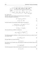
The motion of pneumatic actuators is already linear, but may be too limited with respect to
the requirements; in this case the actuator stroke can be multiplied by means of a pulley
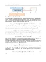
device of the kind shown in figure 12. In this device, the actuator 1 exerts his action on a
group of mobile pulleys 2; the cable 3 leans on mobile pulleys 2 and fixed pulleys 4-5; a
rotating potentiometer 6, connected to the fixed pulley 5, measures the cable motion. In this
example the actuator stroke is multiplied by 6, and its force is divided by the same factor.
Such a device allows limiting the size of the actuator, but on the other side it introduces
further friction in the system. Of course the stroke multiplier may also be used when
adopting linear electric motors, in order to limit their size.
Fig. 12. Device for stroke multiplication of a linear actuator.
In case of pneumatic actuation of the cables, particular attention is required for the control of
the supply pressure of the actuator. A simple and economic way is to use on-off valves
controlled by PWM logic, but it is necessary to achieve a good compromise, considering the
following points:
(a)
the PWM signal introduces vibrations in the pressure value, generating the force
reflection; such vibrations may be reduced by a proper dimensioning of the pneumatic
system, creating a low-pass pneumatic filter that, on the other side, may penalize the
system dynamics;
(b)
the overall dynamics also depends on the valve size; in particular the discharge valves
should be properly dimensioned.
As regards the control of cable tensions, it is possible to choose two different strategies:
(a)
Open loop control. In this case the tension value calculated by the control system is
used as reference for the motor torque (in case of electrical actuation of cables) or the
cylinder pressure (in case of pneumatic actuation). The actual cable tension will be
therefore affected by errors due to the friction along the transmission line and various
disturbances such as cogging torque, PWM control, etc.
(b) Closed loop control. The reference value is compared to a direct measure of the cable
tension, through a convenient sensor. The control is in general more accurate, but
instabilities may arise, due to the non-linearities present in the system, such as friction,
cogging torque of electric motors, static and dynamic characteristics of pneumatic
valves.
Among all the possible options presented in the previous paragraphs, a choice must be
made according to the project specifications, desired performances and, of course, budget
limitations.
6. Conclusion
Cable driven robotic devices present peculiar aspects, requiring the solution of very specific
problems.
As regards the determination of the main operational characteristics, like the workspace, it is
necessary to consider that such devices are often parallel and redundant structures.
Moreover, cables can only exert traction forces. As a consequence, the development of such
structures requires coping with two main aspects:
(a)
the solution of forward kinematics and inverse statics, necessary for the remote control
of the slave device and the force reflection on the operator, are usually very complicated
and often a closed form does not exist;
(b)
it is useful to find a convenient layout of the attach points on the mobile platform, in
order to obtain closed-form solutions or optimal numerical solutions for the kinematical
and static equations.
The workspace characteristics also depend on the number of cables and the layout of their
passing points on the fixed structure, but it is difficult to foresee those performances in the
design phase and to evaluate them in an objective way. Therefore it is necessary to develop
methods aimed at finding out the shape of the six-dimensional workspace, expressing it in a
graphical form and evaluating its characteristics by means of objective numerical
parameters.
The actuation by cables needs particular attention as regards both the generation and the
transmission of cable tensions. This has required a wide research activity concerning the
kind of actuators to be used and the mechanical aspects of the transmission lines.
As regards the actuators, it must be noticed that their action must be generated at very low
velocities, often near the stall condition. Therefore, particular care must be devoted to the
choice of technology (electrical or pneumatic), to the kind of actuator and to the way of
controlling the force or torque.
The physical characteristics of the cable and its path have direct influence on the control
accuracy. The cables connect the operator with the motors and with the device sensors; the
accuracy of the device is affected by the friction acting on the cable and by characteristics
like longitudinal compliance and flexural stiffness; those phenomena may only be partially
compensated by the control system, therefore the choice of the cable is a very delicate point.
The research described here has faced all the aspects above mentioned. Several original
solutions reported have been described in detail in previous works.
Future work will be devoted to improve the way of controlling the reflection forces, which
has been spotted as the most delicate aspect for the accuracy of this kind of devices.
Cabledrivendevicesfortelemanipulation 189
Pneumatic actuators present noticeable friction, due to the seals and also to the fluidic
resistance of the air through the various orifices; even the adoption of a membrane
pneumatic actuator cannot completely eliminate friction.
The motion of pneumatic actuators is already linear, but may be too limited with respect to
the requirements; in this case the actuator stroke can be multiplied by means of a pulley
device of the kind shown in figure 12. In this device, the actuator 1 exerts his action on a
group of mobile pulleys 2; the cable 3 leans on mobile pulleys 2 and fixed pulleys 4-5; a
rotating potentiometer 6, connected to the fixed pulley 5, measures the cable motion. In this
example the actuator stroke is multiplied by 6, and its force is divided by the same factor.
Such a device allows limiting the size of the actuator, but on the other side it introduces
further friction in the system. Of course the stroke multiplier may also be used when
adopting linear electric motors, in order to limit their size.
Fig. 12. Device for stroke multiplication of a linear actuator.
In case of pneumatic actuation of the cables, particular attention is required for the control of
the supply pressure of the actuator. A simple and economic way is to use on-off valves
controlled by PWM logic, but it is necessary to achieve a good compromise, considering the
following points:
(a)
the PWM signal introduces vibrations in the pressure value, generating the force
reflection; such vibrations may be reduced by a proper dimensioning of the pneumatic
system, creating a low-pass pneumatic filter that, on the other side, may penalize the
system dynamics;
(b)
the overall dynamics also depends on the valve size; in particular the discharge valves
should be properly dimensioned.
As regards the control of cable tensions, it is possible to choose two different strategies:
(a)
Open loop control. In this case the tension value calculated by the control system is
used as reference for the motor torque (in case of electrical actuation of cables) or the
cylinder pressure (in case of pneumatic actuation). The actual cable tension will be
therefore affected by errors due to the friction along the transmission line and various
disturbances such as cogging torque, PWM control, etc.
(b) Closed loop control. The reference value is compared to a direct measure of the cable
tension, through a convenient sensor. The control is in general more accurate, but
instabilities may arise, due to the non-linearities present in the system, such as friction,
cogging torque of electric motors, static and dynamic characteristics of pneumatic
valves.
Among all the possible options presented in the previous paragraphs, a choice must be
made according to the project specifications, desired performances and, of course, budget
limitations.
6. Conclusion
Cable driven robotic devices present peculiar aspects, requiring the solution of very specific
problems.
As regards the determination of the main operational characteristics, like the workspace, it is
necessary to consider that such devices are often parallel and redundant structures.
Moreover, cables can only exert traction forces. As a consequence, the development of such
structures requires coping with two main aspects:
(a)
the solution of forward kinematics and inverse statics, necessary for the remote control
of the slave device and the force reflection on the operator, are usually very complicated
and often a closed form does not exist;
(b)
it is useful to find a convenient layout of the attach points on the mobile platform, in
order to obtain closed-form solutions or optimal numerical solutions for the kinematical
and static equations.
The workspace characteristics also depend on the number of cables and the layout of their
passing points on the fixed structure, but it is difficult to foresee those performances in the
design phase and to evaluate them in an objective way. Therefore it is necessary to develop
methods aimed at finding out the shape of the six-dimensional workspace, expressing it in a
graphical form and evaluating its characteristics by means of objective numerical
parameters.
The actuation by cables needs particular attention as regards both the generation and the
transmission of cable tensions. This has required a wide research activity concerning the
kind of actuators to be used and the mechanical aspects of the transmission lines.
As regards the actuators, it must be noticed that their action must be generated at very low
velocities, often near the stall condition. Therefore, particular care must be devoted to the
choice of technology (electrical or pneumatic), to the kind of actuator and to the way of
controlling the force or torque.
The physical characteristics of the cable and its path have direct influence on the control
accuracy. The cables connect the operator with the motors and with the device sensors; the
accuracy of the device is affected by the friction acting on the cable and by characteristics
like longitudinal compliance and flexural stiffness; those phenomena may only be partially
compensated by the control system, therefore the choice of the cable is a very delicate point.
The research described here has faced all the aspects above mentioned. Several original
solutions reported have been described in detail in previous works.
Future work will be devoted to improve the way of controlling the reflection forces, which
has been spotted as the most delicate aspect for the accuracy of this kind of devices.
RemoteandTelerobotics190
Acknowledgements
The work presented here has been partially funded by the Robotics and Telescience
Research projects of the
Italian Antarctic Research Program (PNRA).
A further support was provided by the Italian Ministry of University and Research.
7. References
Batsomboon, P.; Tosunoglu, S. & Repperger, D.W. (2000). A Survey of Telesensation and
Teleoperation Technology with Virtual Reality and Force Reflection Capabilities,
International Journal of Modelling and Simulation, Vol. 20, No. 1, (2000) pp. 79-88,
ISSN 0228-6203
Bostelman, R.; Albus, J.; Dagalakis, N. & Jacoff, A. (1996). RoboCrane project: An advanced
concept for large scale manufacturing,
Proceedings of AUVSI Conference, Orlando,
FL, July 1996
Conklin, W. & Tosunoglu, S. (1996). Conceptual Design of a Universal Bilateral Manual
Controller,
Proceedings of 1996 Florida Conference on Recent Advances in Robotics, pp.
187-191, Florida Atlantic University, Boca Raton, Florida, April 1996
Ferraresi, C.; Pastorelli, S. & Pescarmona F. (2001). Workspace analysis and design criteria of
6 d.o.f. wire parallel structures,
Proceedings of 10th International Workshop on Robotics
in Alpe-Adria-Danube Region RAAD ’01
, CD-Proceedings, paper RD-062, Vienna,
Austria, May 2001
Ferraresi, C.; Paoloni, M.; Pastorelli, S. & Pescarmona, F. (2004). A new 6-DOF parallel
robotic structure actuated by wires: The WiRo-6.3,
Journal of Robotics Systems, Vol.
21, No. 11 (November 2004) pp. 581-595, ISSN 0741-2223
Ferraresi, C.; Carello, M.; Pescarmona, F. & Grassi, R. (2006). Wire-driven pneumatic
actuation of a new 6-dof haptic master,
Proceedings of ESDA2006 8th Biennial ASME
Conference on Engineering Systems Design and Analysis
, ISBN 0-7918-3779-3, Torino,
Italy, July 2006
Ferraresi, C.; Paoloni, M. & Pescarmona, F. (2007). A new methodology for the
determination of the workspace of six-DOF redundant parallel structures actuated
by nine wires,
Robotica, Vol. 25, No.1 (January 2007) pp. 113-120, ISSN 0263-5747
Hoppe, L.F.E. (1997). Performance improvement of Dyneema
®
in ropes, Proceedings of
OCEANS '97 MTS/IEEE Conference
, pp. 314-318, ISBN 0-7803-4108-2, Halifax, NS,
Canada, October 1997
Kawamura, S.; Choe, W.; Tanaka, S. & Pandian, S.R. (1995). Development of an Ultrahigh
Speed Robot FALCON Using Wire Drive System,
Proceedings of IEEE Int. Conference
on Robotics and Automation
, pp. 215-220, ISBN 0-7803-1965-6, Nagoya, Aichi, Japan,
May 1995
McAffee, D.A. & Fiorini, P. (1991). Hand Controller Design Requirements and Performance
Issues in Telerobotics,
Proceedings of Advanced Robotics, 1991. Proceedings of Robots in
Unstructured Environments, 91 ICAR
, pp. 186-192, ISBN 0-7803-0078-5, Pisa, Italy,
June 1991
Anoriginalapproachforabetterremotecontrolofanassistiverobot 191
Anoriginalapproachforabetterremotecontrolofanassistiverobot
Sébastien Delarue, Paul Nadrag, Antonio Andriatrimoson, Etienne Colle and Philippe
Hoppenot
X
An original approach for a better
remote control of an assistive robot
Sébastien Delarue, Paul Nadrag, Antonio Andriatrimoson,
Etienne Colle and Philippe Hoppenot
IBISC Laboratory - University of Evry Val d’Essonne - France
Abstract
Many researches have been done in the field of assistive robotics in the last few years. The
first application field was helping with the disabled people’s assistance. Different works
have been performed on robotic arms in three kinds of situations. In the first case, static arm,
the arm was principally dedicated to office tasks like telephone, fax… Several autonomous
modes exist which need to know the precise position of objects. In the second configuration,
the arm is mounted on a wheelchair. It follows the person who can employ it in more use
cases. But if the person must stay in her/his bed, the arm is no more useful. In a third
configuration, the arm is mounted on a separate platform. This configuration allows the
largest number of use cases but also poses more difficulties for piloting the robot.
The second application field of assistive robotics deals with the assistance at home of people
losing their autonomy, for example a person with cognitive impairment. In this case, the
assistance deals with two main points: security and cognitive stimulation. In order to ensure
the safety of the person at home, different kinds of sensors can be used to detect alarming
situations (falls, low cardiac pulse rate…). For assisting a distant operator in alarm
detection, the idea is to give him the possibility to have complementary information from a
mobile robot about the person’s activity at home and to be in contact with the person.
Cognitive stimulation is one of the therapeutic means used to maintain as long as possible
the maximum of the cognitive capacities of the person. In this case, the robot can be used to
bring to the person cognitive stimulation exercises and stimulate the person to perform
them.
To perform these tasks, it is very difficult to have a totally autonomous robot. In the case of
disabled people assistance, it is even not the will of the persons who want to act by
themselves. The idea is to develop a semi-autonomous robot that a remote operator can
manually pilot with some driving assistances. This is a realistic and somehow desired
solution. To achieve that, several scientific problems have to be studied. The first one is
human-machine-cooperation. How a remote human operator can control a robot to perform
a desired task? One of the key points is to permit the user to understand clearly the way the
robot works. Our original approach is to analyse this understanding through appropriation
concept introduced by Piaget in 1936. As the robot must have capacities of perception
11
RemoteandTelerobotics192
decision and action, the second scientific point to address is the robot capacities of
autonomy (obstacle avoidance, localisation, path planning…). These two points lead to
propose different control modes of the robot by a remote operator, from a totally manual
mode to a totally autonomous mode. The most interesting modes are the shared control
modes in which the control of the degrees of freedom is shared between the human operator
and the robot. The third point is to deal with delay. Indeed, the distance between the remote
operator and the robot induces communication delays that must be taken into account in
terms of feedback information to the user. We will conclude this study with several
evaluations to validate our approach.
1. Introduction
Many researches have been done in the field of assistive robotics in the last few years. The
first application field was helping with the disabled people’s assistance. Different works
have been performed on robotic arms in three kinds of situation. In the first case, static arm,
the arm was principally dedicated to office tasks like telephone, fax… Several autonomous
modes exist which need to know the precise position of objects. In the second configuration,
the arm is mounted on a wheelchair. It follows the person who can employ it in more use
cases. But if the person must stay in her/his bed, the arm is no more useful. In a third
configuration, the arm is mounted on a separate platform. This configuration allows the
largest number of use cases but also poses more difficulties for piloting the robot.
The second application field of assistive robotics deals with the assistance at home of people
losing their autonomy, for example a person with cognitive impairment. In this case, the
assistance deals with two main points: security and cognitive stimulation. In order to ensure
the safety of the person at home, different kinds of sensors can be used to detect alarming
situations (falls, low cardiac pulse rate…). For assisting a distant operator in alarm
detection, the idea is to give him the possibility to have complementary information from a
mobile robot about the person’s activity at home and to be in contact with the person.
Cognitive stimulation is one of the therapeutic means used to maintain as long as possible
the maximum of the cognitive capacities of the person. In this case, the robot can be used to
bring to the person cognitive stimulation exercises and stimulate the person to perform
them.
Different works deal with autonomous robotics. They have several drawbacks in these kinds
of application. Concerning disabled people assistance, persons want to act by
herself/himself on the environment. In the case of people loosing their autonomy, one
important point is to permit human-human interaction, through a robot seen as
intermediary communication. One can also notice that autonomous robotics can not yet
propose robots with several days of autonomy (except for spatial missions but at very
expensive costs and with limited action capabilities). Our option is to develop remote
control robots. That has two main advantages. As human being is in the control loop, it is
possible to use her/his capacities, especially decision ones, which are the most difficult to
get from a robot. That permits to assure total autonomy. The second point is that the remote
operator is involved in the performed task, which is for example a clear demand from
disabled people using technical assistance. This choice implies that a mission is realised by
close Human Machine Cooperation between the robot and the human operator. It is also
clear that the robot has some kinds of autonomous capacities, which can be used by the
remote operator if needed.
The first part of this paper deals with autonomy capacities of the robot. It is essential to know
what the robot can do to think about Human Machine Cooperation, which is the main point of
the second part. We also propose different evaluations results in the last part of the paper.
2. Robot capacity of autonomy
Displacement in an environment is realised in two steps. The first one is the description of
the trajectory to perform to reach the given goal. The second one consists in following the
previous trajectory, avoiding unexpected obstacles. To make these two steps possible, the
system needs to have information on its environment and the capacity to localise itself in
this environment. We do not address the case in which the system has no information on its
environment and builds itself a representation of it, using SLAM techniques. We suppose
the system has a sufficient precise knowledge of the environment, which is the case in our
application field. In short, displacement in an environment requires tow kinds of capacities:
path planning and obstacle avoidance. A combination of these two capacities gives the robot
navigation capacities. Localisation is also needed to achieve displacements toward a goal.
2.1 Trajectory planning
This is the first step of autonomy and permits to define the trajectory the robot has to follow.
[Latombe91] presents the three main method families for planning: road maps, cell
decomposition and potential fields. Before presenting them briefly, it is useful to define
what free space is.
Free space describes all the positions the robot can reach taking into account environment
information. In 2D mobile robotics, that represents all the (x, y, ) positions where the robot
can arrive. To simplify computation algorithms, a classical solution is to describe a kind of
"growing" obstacle obtained by extension of the workspace by the dimensions of the robot.
In that case, each orientation of the robot generates a workspace in which the robot can be
considered as a point. In the case of a circular robot, only one workspace is needed. We
introduced imaginary obstacles around the door to make the planned trajectory easier to
follow.
The study of the connectivity of the robot’s free space enable to determine a network of 1
dimension curves called a roadmap, which describe all possible trajectories from an initial
point to a goal point. Among all possible paths, only one is chosen. A
*
algorithm is well
adapted for this work. Given a cost function, it determines the optimal path. It is possible to
optimise the distance, but the function can also take into account the amount of energy,
perception, capacities of the robot. In the case of cell decomposition, the workspace of the
robot is split into several parts called cells. They are built to assure that all couples of points
inside the same cell are linkable by a straight line. A graph linking all the adjacent cells is
also built, which is called the connectivity graph. The idea of potential fields is to determine
an artificial potential field representing the constraints given by the environment. Obstacles
create a repulsive force while the goal creates an attractive force. This method has a well-
known major drawback: the function has local minima, which are not the goal.
Anoriginalapproachforabetterremotecontrolofanassistiverobot 193
decision and action, the second scientific point to address is the robot capacities of
autonomy (obstacle avoidance, localisation, path planning…). These two points lead to
propose different control modes of the robot by a remote operator, from a totally manual
mode to a totally autonomous mode. The most interesting modes are the shared control
modes in which the control of the degrees of freedom is shared between the human operator
and the robot. The third point is to deal with delay. Indeed, the distance between the remote
operator and the robot induces communication delays that must be taken into account in
terms of feedback information to the user. We will conclude this study with several
evaluations to validate our approach.
1. Introduction
Many researches have been done in the field of assistive robotics in the last few years. The
first application field was helping with the disabled people’s assistance. Different works
have been performed on robotic arms in three kinds of situation. In the first case, static arm,
the arm was principally dedicated to office tasks like telephone, fax… Several autonomous
modes exist which need to know the precise position of objects. In the second configuration,
the arm is mounted on a wheelchair. It follows the person who can employ it in more use
cases. But if the person must stay in her/his bed, the arm is no more useful. In a third
configuration, the arm is mounted on a separate platform. This configuration allows the
largest number of use cases but also poses more difficulties for piloting the robot.
The second application field of assistive robotics deals with the assistance at home of people
losing their autonomy, for example a person with cognitive impairment. In this case, the
assistance deals with two main points: security and cognitive stimulation. In order to ensure
the safety of the person at home, different kinds of sensors can be used to detect alarming
situations (falls, low cardiac pulse rate…). For assisting a distant operator in alarm
detection, the idea is to give him the possibility to have complementary information from a
mobile robot about the person’s activity at home and to be in contact with the person.
Cognitive stimulation is one of the therapeutic means used to maintain as long as possible
the maximum of the cognitive capacities of the person. In this case, the robot can be used to
bring to the person cognitive stimulation exercises and stimulate the person to perform
them.
Different works deal with autonomous robotics. They have several drawbacks in these kinds
of application. Concerning disabled people assistance, persons want to act by
herself/himself on the environment. In the case of people loosing their autonomy, one
important point is to permit human-human interaction, through a robot seen as
intermediary communication. One can also notice that autonomous robotics can not yet
propose robots with several days of autonomy (except for spatial missions but at very
expensive costs and with limited action capabilities). Our option is to develop remote
control robots. That has two main advantages. As human being is in the control loop, it is
possible to use her/his capacities, especially decision ones, which are the most difficult to
get from a robot. That permits to assure total autonomy. The second point is that the remote
operator is involved in the performed task, which is for example a clear demand from
disabled people using technical assistance. This choice implies that a mission is realised by
close Human Machine Cooperation between the robot and the human operator. It is also
clear that the robot has some kinds of autonomous capacities, which can be used by the
remote operator if needed.
The first part of this paper deals with autonomy capacities of the robot. It is essential to know
what the robot can do to think about Human Machine Cooperation, which is the main point of
the second part. We also propose different evaluations results in the last part of the paper.
2. Robot capacity of autonomy
Displacement in an environment is realised in two steps. The first one is the description of
the trajectory to perform to reach the given goal. The second one consists in following the
previous trajectory, avoiding unexpected obstacles. To make these two steps possible, the
system needs to have information on its environment and the capacity to localise itself in
this environment. We do not address the case in which the system has no information on its
environment and builds itself a representation of it, using SLAM techniques. We suppose
the system has a sufficient precise knowledge of the environment, which is the case in our
application field. In short, displacement in an environment requires tow kinds of capacities:
path planning and obstacle avoidance. A combination of these two capacities gives the robot
navigation capacities. Localisation is also needed to achieve displacements toward a goal.
2.1 Trajectory planning
This is the first step of autonomy and permits to define the trajectory the robot has to follow.
[Latombe91] presents the three main method families for planning: road maps, cell
decomposition and potential fields. Before presenting them briefly, it is useful to define
what free space is.
Free space describes all the positions the robot can reach taking into account environment
information. In 2D mobile robotics, that represents all the (x, y, ) positions where the robot
can arrive. To simplify computation algorithms, a classical solution is to describe a kind of
"growing" obstacle obtained by extension of the workspace by the dimensions of the robot.
In that case, each orientation of the robot generates a workspace in which the robot can be
considered as a point. In the case of a circular robot, only one workspace is needed. We
introduced imaginary obstacles around the door to make the planned trajectory easier to
follow.
The study of the connectivity of the robot’s free space enable to determine a network of 1
dimension curves called a roadmap, which describe all possible trajectories from an initial
point to a goal point. Among all possible paths, only one is chosen. A
*
algorithm is well
adapted for this work. Given a cost function, it determines the optimal path. It is possible to
optimise the distance, but the function can also take into account the amount of energy,
perception, capacities of the robot. In the case of cell decomposition, the workspace of the
robot is split into several parts called cells. They are built to assure that all couples of points
inside the same cell are linkable by a straight line. A graph linking all the adjacent cells is
also built, which is called the connectivity graph. The idea of potential fields is to determine
an artificial potential field representing the constraints given by the environment. Obstacles
create a repulsive force while the goal creates an attractive force. This method has a well-
known major drawback: the function has local minima, which are not the goal.
RemoteandTelerobotics194
In our project, we use a visibility graph with the A
*
algorithm. In our application (the robot
evolves indoors), the environment is sufficiently well-known so that the built graph is
nearly complete. Moreover, cost function is interesting to use because we can choose several
parameters to optimise the trajectory. All these aspects are detailed in [Hoppenot96] and
[Benreguieg97].
2.2 Obstacle avoidance
A robot can follow the trajectory planned as above only if the environment is totally known.
That is why local navigation systems have been developed based on robot sensors
acquisition. It is now usual to combine path planning and local navigation. In that case, path
planning is in charge of long terms goal while local navigation only deals with obstacle
avoidance. Some qualitative reasoning theories have been developed. We propose a solution
based on fuzzy logic to process obstacle avoidance ([Zadeh65], [Kanal88], [Lee90]).
When the vehicle is moving towards the target and the front sensors detect an obstacle
located on the path, an avoiding strategy is necessary. The selected method consists in
reaching the middle of a collision-free space. The used navigator is built with a fuzzy
controller based on a set of rules as follows:
If Rn is x
i
and Ln is y
i
Then is t
i
and if Fn is z
i
then
v is u
i
"
else…
x
i
, y
i
, z
i
, t
i
and u
i
are a linguistic labels of a fuzzy partition of the universes of discourse of
the inputs Rn, Ln and Fn and the outputs and v, respectively. The inputs variables are the
normalised measured distances on the right R, on the left L and in front F such as:
,
inf
and
n n n
R L F
R L F
R L R L
where inf is the sensor maximum range.
The output variables are the angular and the linear speeds. On simplicity grounds, the
shape of the membership functions is triangular and the sum of the membership degrees for
each variable is always equal to 1. The universes of discourse are normalised between -1 and
1, for , and 0 and 1 for the other ones.
Each universe of discourse is shared in five fuzzy subsets. The linguistic labels are defined
as follows:
Z : Zero NB : Negative Big
S : Small NS : Negative Small
M : Medium Z : Zero
B : Big PS : Positive Small
L : Large PB : Positive Big
The whole control rules deduced from a human driver’s intuitive experience is represented
by fifty rules shown in the two following decision tables (Table1 and Table2): 25 rules allow
to determine the angular velocity w and 25 others determine the linear speed v.
B
L
M
S
Z
Z S M B L
1
1
L
L
R
R
NB NB NS NS Z
NB
Z PS PS PB
NS Z PSPS PB
PS PS ZNSNS
NS NS Z PS
PB
n
n
n
n
L
nR
n
PS
PB
F
Z
NS
NB
Z S M B L
1
1
F
F
S S S
S S S
S S B B
B S M L
S S B B
Z Z
Z
Z Z
Z
Z
n
n
n
Table 1. Angular velocity rules Table 2. Linear speed rules
An example of such fuzzy rules is:
If ( R
n
is Large ) and ( L
n
is Large ) then ( is Zero ) and if ( f is Large ) then ( v is Large ).
Complete results are detailed in [Hoppenot96] and [Benreguieg97].
2.3 Navigation behaviour
The and v control actions produced by the above fuzzy controller handle the robot to
avoid the obstacles when it is attracted by the immediate nearest subgoal (SG
k
). This latter
exercises an attractive force which guides the robot to its destination. The actions (
a
and
v
a
) generated by this force are modulated by the inverse of the distance
k
SGR ,
between the centre of the robot and the k
th
subgoal.
0.2;0.4 0.2;0.4 0.2
0 1
,
1
,
If or or
then: and
else if
then: and
else:
n n n
a a
k
a t
a a a a
k
L R F
v
R SG D
C
v
R SG
0,5 1 . and
a a a av
The setpoints V and applied to the robot result of a linear combination between the
obstacles avoidance and the subgoal attraction.
Anoriginalapproachforabetterremotecontrolofanassistiverobot 195
In our project, we use a visibility graph with the A
*
algorithm. In our application (the robot
evolves indoors), the environment is sufficiently well-known so that the built graph is
nearly complete. Moreover, cost function is interesting to use because we can choose several
parameters to optimise the trajectory. All these aspects are detailed in [Hoppenot96] and
[Benreguieg97].
2.2 Obstacle avoidance
A robot can follow the trajectory planned as above only if the environment is totally known.
That is why local navigation systems have been developed based on robot sensors
acquisition. It is now usual to combine path planning and local navigation. In that case, path
planning is in charge of long terms goal while local navigation only deals with obstacle
avoidance. Some qualitative reasoning theories have been developed. We propose a solution
based on fuzzy logic to process obstacle avoidance ([Zadeh65], [Kanal88], [Lee90]).
When the vehicle is moving towards the target and the front sensors detect an obstacle
located on the path, an avoiding strategy is necessary. The selected method consists in
reaching the middle of a collision-free space. The used navigator is built with a fuzzy
controller based on a set of rules as follows:
If Rn is x
i
and Ln is y
i
Then is t
i
and if Fn is z
i
then
v is u
i
"
else…
x
i
, y
i
, z
i
, t
i
and u
i
are a linguistic labels of a fuzzy partition of the universes of discourse of
the inputs Rn, Ln and Fn and the outputs and v, respectively. The inputs variables are the
normalised measured distances on the right R, on the left L and in front F such as:
,
inf
and
n n n
R L F
R L F
R L R L
where inf is the sensor maximum range.
The output variables are the angular and the linear speeds. On simplicity grounds, the
shape of the membership functions is triangular and the sum of the membership degrees for
each variable is always equal to 1. The universes of discourse are normalised between -1 and
1, for , and 0 and 1 for the other ones.
Each universe of discourse is shared in five fuzzy subsets. The linguistic labels are defined
as follows:
Z : Zero NB : Negative Big
S : Small NS : Negative Small
M : Medium Z : Zero
B : Big PS : Positive Small
L : Large PB : Positive Big
The whole control rules deduced from a human driver’s intuitive experience is represented
by fifty rules shown in the two following decision tables (Table1 and Table2): 25 rules allow
to determine the angular velocity w and 25 others determine the linear speed v.
B
L
M
S
Z
Z S M B L
1
1
L
L
R
R
NB NB NS NS Z
NB
Z PS PS PB
NS Z PSPS PB
PS PS ZNSNS
NS NS Z PS
PB
n
n
n
n
L
nR
n
PS
PB
F
Z
NS
NB
Z S M B L
1
1
F
F
S S S
S S S
S S B B
B S M L
S S B B
Z Z
Z
Z Z
Z
Z
n
n
n
Table 1. Angular velocity rules Table 2. Linear speed rules
An example of such fuzzy rules is:
If ( R
n
is Large ) and ( L
n
is Large ) then ( is Zero ) and if ( f is Large ) then ( v is Large ).
Complete results are detailed in [Hoppenot96] and [Benreguieg97].
2.3 Navigation behaviour
The and v control actions produced by the above fuzzy controller handle the robot to
avoid the obstacles when it is attracted by the immediate nearest subgoal (SG
k
). This latter
exercises an attractive force which guides the robot to its destination. The actions (
a
and
v
a
) generated by this force are modulated by the inverse of the distance
k
SGR ,
between the centre of the robot and the k
th
subgoal.
0.2;0.4 0.2;0.4 0.2
0 1
,
1
,
If or or
then: and
else if
then: and
else:
n n n
a a
k
a t
a a a a
k
L R F
v
R SG D
C
v
R SG
0,5 1 . and
a a a av
The setpoints V and applied to the robot result of a linear combination between the
obstacles avoidance and the subgoal attraction.
RemoteandTelerobotics196
1
min
max
, ,
( , ).
( , ).
If or
then
else
rd s
k k
a
a
a
R SG D R SG D
V Min v v V m s
V Min v v V m s
where Cat, and are coefficients adjusted by experimentation to get the best trajectory
generation.
2.4 Localisation
Planning and navigation (in the sense of following the planned trajectory) are possible only
if the robot has information about its localisation. Localisation methods are divided into two
families. Relative localisation consists in computing present position taking into account the
previous one and the robot displacement. This method is easy to implement in real-time, but
its main drawback is that its error is not bounded and tends to grow with time. Absolute
localisation is based on exteroceptive perception and knowledge of the environment. It is
performed in 4 steps: (i) data acquisition (here with a camera), (ii) primitive extraction (here
segments), (iii) 2D-3D Matching and (iv) position computing. The major part of our work
was done on the last two points.
1
100
10000
1E+06
1E+08
1E+10
1E+12
1E+14
1E+16
1
21
41
61
81
101
121
141
161
181
201
221
241
261
281
301
321
341
361
381
401
421
Image sample
Hypothesis number
maximum number of hypothesis
hypothesis number after pruning
Fig. 1. Pruning performance with unary and binary constraints
Concerning matching methods, they can be classified in two groups: methods which search
a solution in the “correspondence space” such as alignment ([Ayache86], [Lowe87]),
geometric hashing ([Lamdan88]) or interpretation tree search ([Grimson90b], [Grimson87])
and those which search in the “transformation space” such as generalised Hough transform
([Grimson90a]). One of the most popular approaches is the interpretation tree search
introduced by Grimson ([Grimson90b], [Grimson87]). We have proposed a two-stage
method for mobile robot localisation based on a tree search approach and using straight line
correspondences. The first stage serves to select a small set of matching hypothesis. Indeed,
exploiting some particularities of the context, the sets of image lines and model segments are
both divided in two subsets. Two smaller interpretation trees are then obtained. Two
different geometric constraints (a unary constraint and a binary constraint) which can be
applied directly on 2D-3D correspondences are derived and used to prune the interpretation
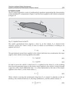
trees. In the second stage, poses corresponding to retained matching hypothesis are
calculated. An error function is used to select the optimal match if it does exist. Figure 1
shows the number of hypotheses to be tested regarding their total number. As the ordinate
axis scale in a logarithm one, the method gives very interesting results. Considering that
point (iv) is the time consumer, it is very important to reduce as much as possible the
number of hypotheses to test. All results can be found in [AitAider05], [AitAider02b] and
[AitAider01].
Position computing (step (iv)) is based on Lowe’s algorithm ([Lowe87]). We have proposed
two main adaptations of this method. First of all, Lowe's method is based on point
correspondences. In this application, the image is first segmented into contours. Contours
generally correspond to physical elements in the work space, such as edges constituted by
intersections between surfaces of the flat. These edges tend to be straight segments. Lines
are easier to extract from contour images and their characterisation by polygonal
approximation is reliable even in the presence of noise. Partial occlusion (due to the view
angle or the presence of non-modelled objects) does not affect line representation
parameters. Furthermore, the extremities of the edges that could possibly be considered as
point features are not always seen in the image due to the dimension of the flat edges in
comparison with their distance to the camera. These reasons make it more prudent to use
straight line correspondences. Thus, the 3D model can simply comprise a set of straight
segments whose extremities have known co-ordinates in the world frame. The second
adaptation concerns the degrees of freedom of the system. Lowe's algorithm works in 6D
(three positions and three orientations). In our context, we have only two positions and one
orientation as the robot evolves in a 2D environment. That gives the possibility to reduce the
number of parameters. The obtained system of equations is still non-linear and contains
multiple unknowns. Convergence properties are highly dependent upon the quality of the
initial estimate of the solution vector. Many situations unfortunately arise in which the robot
is “completely lost” in its environment and has no perception of its actual location. An
approach to reducing the effects of non-linearity is to find a way to uncouple some of the
variables. The rotation and translation parameters have been uncoupled. An initial estimate
of the solution can be found by analytically solving one of these equations. A numerical
optimisation by means of least squares using Newton's method is then to be applied.
Development can be found in [AitAider02a].
3. Human machine cooperation
3.1 Appropriation and human-like behaviour
According to Piaget, the intelligence is before all adaptation ([Piaget36], [Piaget52]). The
functional organization of the living being emerges from the balanced relation which is
established between the individual and the environment. This balance is made possible by
transformations induced by the characteristics of the environment with which a person
interacts. For Piaget, who analyzes the birth of the intelligence in its sensorimotor
dimension, the adaptation can break up into two processes.
The first one is the process of assimilation. According to this author, this process is defined
as the tendency to preserve a behavior. That is made possible thanks to a certain repetition
of the behavior in question which thus is schematized. A scheme constitutes a structured set
of the generalizable characteristics of the action which will allow the reproduction of the
same action even if the scheme is applied to a new but close situation. These schemes
Anoriginalapproachforabetterremotecontrolofanassistiverobot 197
1
min
max
, ,
( , ).
( , ).
If or
then
else
rd s
k k
a
a
a
R SG D R SG D
V Min v v V m s
V Min v v V m s
where Cat, and are coefficients adjusted by experimentation to get the best trajectory
generation.
2.4 Localisation
Planning and navigation (in the sense of following the planned trajectory) are possible only
if the robot has information about its localisation. Localisation methods are divided into two
families. Relative localisation consists in computing present position taking into account the
previous one and the robot displacement. This method is easy to implement in real-time, but
its main drawback is that its error is not bounded and tends to grow with time. Absolute
localisation is based on exteroceptive perception and knowledge of the environment. It is
performed in 4 steps: (i) data acquisition (here with a camera), (ii) primitive extraction (here
segments), (iii) 2D-3D Matching and (iv) position computing. The major part of our work
was done on the last two points.
1
100
10000
1E+06
1E+08
1E+10
1E+12
1E+14
1E+16
1
21
41
61
81
101
121
141
161
181
201
221
241
261
281
301
321
341
361
381
401
421
Image sample
Hypothesis number
maximum number of hypothesis
hypothesis number after pruning
Fig. 1. Pruning performance with unary and binary constraints
Concerning matching methods, they can be classified in two groups: methods which search
a solution in the “correspondence space” such as alignment ([Ayache86], [Lowe87]),
geometric hashing ([Lamdan88]) or interpretation tree search ([Grimson90b], [Grimson87])
and those which search in the “transformation space” such as generalised Hough transform
([Grimson90a]). One of the most popular approaches is the interpretation tree search
introduced by Grimson ([Grimson90b], [Grimson87]). We have proposed a two-stage
method for mobile robot localisation based on a tree search approach and using straight line
correspondences. The first stage serves to select a small set of matching hypothesis. Indeed,
exploiting some particularities of the context, the sets of image lines and model segments are
both divided in two subsets. Two smaller interpretation trees are then obtained. Two
different geometric constraints (a unary constraint and a binary constraint) which can be
applied directly on 2D-3D correspondences are derived and used to prune the interpretation
trees. In the second stage, poses corresponding to retained matching hypothesis are
calculated. An error function is used to select the optimal match if it does exist. Figure 1
shows the number of hypotheses to be tested regarding their total number. As the ordinate
axis scale in a logarithm one, the method gives very interesting results. Considering that
point (iv) is the time consumer, it is very important to reduce as much as possible the
number of hypotheses to test. All results can be found in [AitAider05], [AitAider02b] and
[AitAider01].
Position computing (step (iv)) is based on Lowe’s algorithm ([Lowe87]). We have proposed
two main adaptations of this method. First of all, Lowe's method is based on point
correspondences. In this application, the image is first segmented into contours. Contours
generally correspond to physical elements in the work space, such as edges constituted by
intersections between surfaces of the flat. These edges tend to be straight segments. Lines
are easier to extract from contour images and their characterisation by polygonal
approximation is reliable even in the presence of noise. Partial occlusion (due to the view
angle or the presence of non-modelled objects) does not affect line representation
parameters. Furthermore, the extremities of the edges that could possibly be considered as
point features are not always seen in the image due to the dimension of the flat edges in
comparison with their distance to the camera. These reasons make it more prudent to use
straight line correspondences. Thus, the 3D model can simply comprise a set of straight
segments whose extremities have known co-ordinates in the world frame. The second
adaptation concerns the degrees of freedom of the system. Lowe's algorithm works in 6D
(three positions and three orientations). In our context, we have only two positions and one
orientation as the robot evolves in a 2D environment. That gives the possibility to reduce the
number of parameters. The obtained system of equations is still non-linear and contains
multiple unknowns. Convergence properties are highly dependent upon the quality of the
initial estimate of the solution vector. Many situations unfortunately arise in which the robot
is “completely lost” in its environment and has no perception of its actual location. An
approach to reducing the effects of non-linearity is to find a way to uncouple some of the
variables. The rotation and translation parameters have been uncoupled. An initial estimate
of the solution can be found by analytically solving one of these equations. A numerical
optimisation by means of least squares using Newton's method is then to be applied.
Development can be found in [AitAider02a].
3. Human machine cooperation
3.1 Appropriation and human-like behaviour
According to Piaget, the intelligence is before all adaptation ([Piaget36], [Piaget52]). The
functional organization of the living being emerges from the balanced relation which is
established between the individual and the environment. This balance is made possible by
transformations induced by the characteristics of the environment with which a person
interacts. For Piaget, who analyzes the birth of the intelligence in its sensorimotor
dimension, the adaptation can break up into two processes.
The first one is the process of assimilation. According to this author, this process is defined
as the tendency to preserve a behavior. That is made possible thanks to a certain repetition
of the behavior in question which thus is schematized. A scheme constitutes a structured set
of the generalizable characteristics of the action which will allow the reproduction of the
same action even if the scheme is applied to a new but close situation. These schemes
RemoteandTelerobotics198
constitute an active organization of the lived experiment which integrates the past. They
thus include a structure which has a history and progressively changes with the variety of
the situations met. The history of a scheme is that of its generalization but also of its
adjustment to the situation to which it is applied. Generalization is conceptualized by the
process of assimilation. Concretely, by their proximity of appearance or situation, the use of
new objects can be assimilated to pre-existent schemes. The property of differentiation, as
for it, refers to the second process responsible for the adaptation called by Piaget
accommodation. When the complexity of the situation does not allow a direct assimilation, a
mechanism of accommodation builds a new scheme by important modifications of pre-
existent schemes. If one takes the example of the acquisition of the manipulation of a stick
by the young child ([Piaget36], [Piaget52]), one completely understands the nature
complementary of this process with that of the assimilation. In this experiment, a child is
placed vis-a-vis a sofa on which a bottle is posed out of range. However within his hand
range, there is a stick. Initially he tries to seize the bottle directly, then seizes the stick and
strikes with the stick and by chance makes object fall. When the bottle is on the ground, he
continues to strike by observing the movements obtained, then he ends up pushing the
object with the stick to bring it back towards him. Later, in the absence of the stick, he seizes
a book to bring closer the bottle. The child thus, first of all, implemented a scheme already
made up - to strike with a stick - but this assimilation of the situation to the scheme does not
make it possible to succeed each time. Consequently the scheme gradually will be adapted
in order to manage the displacement of the object, until leading to a new scheme: to push
with a stick. Lastly, this one will be generalized to other objects, here a book. The same
mechanism is applied to the man-machine relation. The development of sensorimotor
schemes in the young child is relatively transposable with the situation of the operator
having to build schemes of action for controlling the robot. When the machine presents
operating modes close to those known by the operator, he builds robot control schemes by
an assimilation process based on preexistent schemes. On the contrary, if the machine
operating is completely different, the person is obliged to accommodate. It is this principle
of adaptation, at Piaget sense, applied to the man-machine relation which we describe as
mechanism of appropriation.
3.2 Ergonomic design
Appropriation by an
accommodation
process
Machine
User
Appropriation by
an assimilation
process
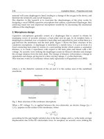
Fig. 2. Application of the Piaget model of adaptation to the Man-machine Co-operation
The preceding considerations expose that the nature of the adaptation of the human to the
machine is strongly dependent on the operating difference between these two entities
(Figure 2.). If the difference is weak, the adaptation is carried out by a process with a
dominant of assimilation, i.e. by the generalization of the initial schemes relevant for the
control of the machine. Conversely, if there is a high difference of operating, the operator is
confronted with a situation which is completely unfamiliar for him. It is thus the process of
accommodation which becomes, for a time, dominating. It leads to the transformation and
reorganization of available schemes, which gradually produce new compositions of schemes
allowing the reproducible management of the new class of situations. It comes out from
these observations that the question of the difference existing between the schemes and
initial representations of the operators and, the schemes and representations necessary to
control the machine are crucial in the ergonomic design of the human-machine co-operation.
Within this framework, two complementary approaches are conceivable.
The first option is to seek to reduce the difference between the existent schemes of the
operator and those appropriated to the control of the machine. The approach consists in
considering the machine as the prolongation of the motor functions of the user. Thus, when
such an assumption is relevant, the user will tend to give his own characteristics and
properties to the machine ([Gaillard93]). In this case, an anthropomorphic design seems to
be well suited in order to build a directly appropriable tool by the assimilation process.
However, in many situations, such a human-machine compatibility is not easily reachable.
This is why the second option aims at taking note of the mismatch between schemes
necessary to control the machine and those of the user, insofar as the difference is regarded
as not significantly reducible. Consequently, the ergonomic design will seek to facilitate the
conceptualization of the difference by an accommodation process based on learning.
3.3 Application context
Within the framework of maintenance in residence, a robot able to move, to handle usual
objects and to perceive its environment can be an essential complement to the other
technological means placed at the disposal of a person with reduced autonomy for her/his
safety and in order to ensure other services like the tele-survey, the tele-health, and the
social relation… If we take the principle that the robot is semi-autonomous, the user remote
controls it (Fi3).
Fig. 3. Remote control situation (adapted from [Fong01])
Anoriginalapproachforabetterremotecontrolofanassistiverobot 199
constitute an active organization of the lived experiment which integrates the past. They
thus include a structure which has a history and progressively changes with the variety of
the situations met. The history of a scheme is that of its generalization but also of its
adjustment to the situation to which it is applied. Generalization is conceptualized by the
process of assimilation. Concretely, by their proximity of appearance or situation, the use of
new objects can be assimilated to pre-existent schemes. The property of differentiation, as
for it, refers to the second process responsible for the adaptation called by Piaget
accommodation. When the complexity of the situation does not allow a direct assimilation, a
mechanism of accommodation builds a new scheme by important modifications of pre-
existent schemes. If one takes the example of the acquisition of the manipulation of a stick
by the young child ([Piaget36], [Piaget52]), one completely understands the nature
complementary of this process with that of the assimilation. In this experiment, a child is
placed vis-a-vis a sofa on which a bottle is posed out of range. However within his hand
range, there is a stick. Initially he tries to seize the bottle directly, then seizes the stick and
strikes with the stick and by chance makes object fall. When the bottle is on the ground, he
continues to strike by observing the movements obtained, then he ends up pushing the
object with the stick to bring it back towards him. Later, in the absence of the stick, he seizes
a book to bring closer the bottle. The child thus, first of all, implemented a scheme already
made up - to strike with a stick - but this assimilation of the situation to the scheme does not
make it possible to succeed each time. Consequently the scheme gradually will be adapted
in order to manage the displacement of the object, until leading to a new scheme: to push
with a stick. Lastly, this one will be generalized to other objects, here a book. The same
mechanism is applied to the man-machine relation. The development of sensorimotor
schemes in the young child is relatively transposable with the situation of the operator
having to build schemes of action for controlling the robot. When the machine presents
operating modes close to those known by the operator, he builds robot control schemes by
an assimilation process based on preexistent schemes. On the contrary, if the machine
operating is completely different, the person is obliged to accommodate. It is this principle
of adaptation, at Piaget sense, applied to the man-machine relation which we describe as
mechanism of appropriation.
3.2 Ergonomic design
Appropriation by an
accommodation
process
Machine
User
Appropriation by
an assimilation
process
Fig. 2. Application of the Piaget model of adaptation to the Man-machine Co-operation
The preceding considerations expose that the nature of the adaptation of the human to the
machine is strongly dependent on the operating difference between these two entities
(Figure 2.). If the difference is weak, the adaptation is carried out by a process with a
dominant of assimilation, i.e. by the generalization of the initial schemes relevant for the
control of the machine. Conversely, if there is a high difference of operating, the operator is
confronted with a situation which is completely unfamiliar for him. It is thus the process of
accommodation which becomes, for a time, dominating. It leads to the transformation and
reorganization of available schemes, which gradually produce new compositions of schemes
allowing the reproducible management of the new class of situations. It comes out from
these observations that the question of the difference existing between the schemes and
initial representations of the operators and, the schemes and representations necessary to
control the machine are crucial in the ergonomic design of the human-machine co-operation.
Within this framework, two complementary approaches are conceivable.
The first option is to seek to reduce the difference between the existent schemes of the
operator and those appropriated to the control of the machine. The approach consists in
considering the machine as the prolongation of the motor functions of the user. Thus, when
such an assumption is relevant, the user will tend to give his own characteristics and
properties to the machine ([Gaillard93]). In this case, an anthropomorphic design seems to
be well suited in order to build a directly appropriable tool by the assimilation process.
However, in many situations, such a human-machine compatibility is not easily reachable.
This is why the second option aims at taking note of the mismatch between schemes
necessary to control the machine and those of the user, insofar as the difference is regarded
as not significantly reducible. Consequently, the ergonomic design will seek to facilitate the
conceptualization of the difference by an accommodation process based on learning.
3.3 Application context
Within the framework of maintenance in residence, a robot able to move, to handle usual
objects and to perceive its environment can be an essential complement to the other
technological means placed at the disposal of a person with reduced autonomy for her/his
safety and in order to ensure other services like the tele-survey, the tele-health, and the
social relation… If we take the principle that the robot is semi-autonomous, the user remote
controls it (Fi3).
Fig. 3. Remote control situation (adapted from [Fong01])
RemoteandTelerobotics200
According to the type of user and use, problems are quite different. The taxonomy defined
by the community of the human-robot interaction is a useful tool which makes it possible to
determine precisely the nature of the interaction between the robot and its user. Taxonomy
gathers the criteria of classification of the interaction in three categories: structural, relational
and operational. If one retains only the relevant criteria for our application, this system is
composed of user, handicapped or not, and of a robot able to move, to seize and handle
objects. In addition, at a given moment, the robot interacts with only one person. Finally the
space-time criterion which belongs to the operational category of taxonomy makes it
possible to distinguish between three types of tasks. If the robot is remote controlled by the
person with reduced autonomy, the robot and the person share the same space i.e. are in the
residence of the person. In this case, two situations are possible, the robot is remote
controlled either in sight or out of sight. On the contrary if the user is a distant person who
remote controls the robot via the Internet, the robot and the user are at different places.
3.4 Control modes
Fig. 4. ARPH system (a) and Human-Machine Interface (b)
The robot of the ARPH project (Figure 4a) is composed of a mobile platform with two
driving powered wheels and a MANUS manipulator arm. An ultrasonic sensor ring makes
possible to avoid obstacles. The robot is equipped with a pan-tilt video camera. The system
– robot and video camera - is remotely controllable via a client/server architecture and a
wireless Wi-Fi network.
The user controls the machine from a computer located at a distant place (Figure 4b) by
using different control modes.
In the Manual mode the operator controls directly all the degrees of freedom of the robot.
In the Assisted mode, the control of the degrees of freedom of the robot is shared between
the user and the machine. This type of mode is the most concerned by a design approach
based on appropriation which aims at determining the most efficient way of sharing the
control of the robot between the user and the system. As such a type of mode depends on
the task and the robot used, it is possible to imagine a large variety of assisted modes.
The key idea is to facilitate an appropriation by the process with a dominant of assimilation
(Figure 1) by giving the robot human-like behaviors. The assumption is that the user builds
by analogy, more intuitively, a realistic mental representation of the robot. The
implementation of behaviors of the human type on the robot rises from the
multidisciplinary step made up of the four following stages:
1- Identification of relevant human behaviors, generally perception-action loops
2- Modeling of the behavior's candidates to extract from them the principal
characteristics
3- Translation of the model resulting from the neurosciences to an implementable
behavior on the robot
4- Evaluation of the mode
We present three examples of assisted-mode design.
3.4.1 Human behaviour candidates
Visio-motor anticipation seems to be a good behavioural solution to palliate the difficulties
of space perception and representation. During a displacement, the axis of the gaze of a
person systematically anticipates the future trajectory. Indeed, in curve trajectories, head
orientation, more precisely gaze direction, of the person is deviated on the inside of the
trajectory. This would guide the trajectory by a systematic anticipation of the trajectory
direction with an interval of 200 milliseconds ([GRA96]).
An analogy can be made between the direction of human glance and that of the pan-tilt
video camera which equips the robot, so we sought to implement on the robot this type of
behavior. The foreseen consequence was an improvement of the speed of execution of the
movement and the fluidity of the trajectories of the robot. Taking into account the functional
architecture of the robot, two implementations of the visual anticipation during a
displacement are conceivable: (i) by automation of the anticipatory movement of the camera
according to the orders of navigation which the operator sends to the robot or conversely (ii)
by automation of the navigation of the robot starting from the orders which the operator
sends to the video camera.
3.4.2 Platform mode
In the situation “I look at where I go” that we call in the following “platform mode”, the
operator directly controls the displacement of the robot. The video camera is oriented only
by a reflex action following the trajectory followed by the robot. From the analogy carried
out between the human glance and the mobile video camera, the latter is automatically
oriented in direction of the point of tangent to the internal trajectory of displacement, i.e. at
the place where visual information is most relevant to guide the locomotion (Figure 5). The
angle a(t) between the axes of the robot and the pan-tilt video camera must be conversely
proportional to the curvature radius of the robot trajectory in order to move the camera
towards the tangent point.
By using the trigonometrical properties, a(t)= arccos [1- (L/2)/r(t)], where L/2 is the half-
width of the robot.
Anoriginalapproachforabetterremotecontrolofanassistiverobot 201
According to the type of user and use, problems are quite different. The taxonomy defined
by the community of the human-robot interaction is a useful tool which makes it possible to
determine precisely the nature of the interaction between the robot and its user. Taxonomy
gathers the criteria of classification of the interaction in three categories: structural, relational
and operational. If one retains only the relevant criteria for our application, this system is
composed of user, handicapped or not, and of a robot able to move, to seize and handle
objects. In addition, at a given moment, the robot interacts with only one person. Finally the
space-time criterion which belongs to the operational category of taxonomy makes it
possible to distinguish between three types of tasks. If the robot is remote controlled by the
person with reduced autonomy, the robot and the person share the same space i.e. are in the
residence of the person. In this case, two situations are possible, the robot is remote
controlled either in sight or out of sight. On the contrary if the user is a distant person who
remote controls the robot via the Internet, the robot and the user are at different places.
3.4 Control modes
Fig. 4. ARPH system (a) and Human-Machine Interface (b)
The robot of the ARPH project (Figure 4a) is composed of a mobile platform with two
driving powered wheels and a MANUS manipulator arm. An ultrasonic sensor ring makes
possible to avoid obstacles. The robot is equipped with a pan-tilt video camera. The system
– robot and video camera - is remotely controllable via a client/server architecture and a
wireless Wi-Fi network.
The user controls the machine from a computer located at a distant place (Figure 4b) by
using different control modes.
In the Manual mode the operator controls directly all the degrees of freedom of the robot.
In the Assisted mode, the control of the degrees of freedom of the robot is shared between
the user and the machine. This type of mode is the most concerned by a design approach
based on appropriation which aims at determining the most efficient way of sharing the
control of the robot between the user and the system. As such a type of mode depends on
the task and the robot used, it is possible to imagine a large variety of assisted modes.
The key idea is to facilitate an appropriation by the process with a dominant of assimilation
(Figure 1) by giving the robot human-like behaviors. The assumption is that the user builds
by analogy, more intuitively, a realistic mental representation of the robot. The
implementation of behaviors of the human type on the robot rises from the
multidisciplinary step made up of the four following stages:
1- Identification of relevant human behaviors, generally perception-action loops
2- Modeling of the behavior's candidates to extract from them the principal
characteristics
3- Translation of the model resulting from the neurosciences to an implementable
behavior on the robot
4- Evaluation of the mode
We present three examples of assisted-mode design.
3.4.1 Human behaviour candidates
Visio-motor anticipation seems to be a good behavioural solution to palliate the difficulties
of space perception and representation. During a displacement, the axis of the gaze of a
person systematically anticipates the future trajectory. Indeed, in curve trajectories, head
orientation, more precisely gaze direction, of the person is deviated on the inside of the
trajectory. This would guide the trajectory by a systematic anticipation of the trajectory
direction with an interval of 200 milliseconds ([GRA96]).
An analogy can be made between the direction of human glance and that of the pan-tilt
video camera which equips the robot, so we sought to implement on the robot this type of
behavior. The foreseen consequence was an improvement of the speed of execution of the
movement and the fluidity of the trajectories of the robot. Taking into account the functional
architecture of the robot, two implementations of the visual anticipation during a
displacement are conceivable: (i) by automation of the anticipatory movement of the camera
according to the orders of navigation which the operator sends to the robot or conversely (ii)
by automation of the navigation of the robot starting from the orders which the operator
sends to the video camera.
3.4.2 Platform mode
In the situation “I look at where I go” that we call in the following “platform mode”, the
operator directly controls the displacement of the robot. The video camera is oriented only
by a reflex action following the trajectory followed by the robot. From the analogy carried
out between the human glance and the mobile video camera, the latter is automatically
oriented in direction of the point of tangent to the internal trajectory of displacement, i.e. at
the place where visual information is most relevant to guide the locomotion (Figure 5). The
angle a(t) between the axes of the robot and the pan-tilt video camera must be conversely
proportional to the curvature radius of the robot trajectory in order to move the camera
towards the tangent point.
By using the trigonometrical properties, a(t)= arccos [1- (L/2)/r(t)], where L/2 is the half-
width of the robot.
RemoteandTelerobotics202
Due to the fact that the ARPH robot is speed controlled by the user, the radius r(t) is
obtained by the ratio between the linear and rotation velocities of the robot.
a(t) = arcc os (1 -(L / 2)/r(t) )
L
r(t)
robo t
tr a
j
ec to r
y
robo t ax is
a( t
a (t)
r( t) -(L /2 )
ca me ra ax is
ta n gen t-
po int
Fig. 5. Implementation of the behavior “I look at where I go”
3.4.3 Camera mode
s(t)
Robot
axis
Robot
planned trajectory
Camera
axis
z(t)
a(t)
d(t)
R
Fig. 6. Implementation of the behavior “I go where I look at”
In the situation “I go where I look at” that we call in the following “camera mode”, the
operator controls the orientation of the camera directly. The orientation of the robot will be
computed from the orientation of the camera. Contrary to the preceding model, the vision is
now actively controlled by the user and the displacement of the robot is automated. The
model is inspired from the behavior of visual anticipation which consists to fix a reference
mark and to maintain it in its visual field in order to describe an ideal trajectory around it.
The great advantage of this situation is that it makes it possible the operator to visualize
continuously the obstacle nearest to the robot limiting the collision risk.
The angle of navigation of the robot s(t) is defined by the difference between the angle a(t),
between the axes of the robot and the pan-tilt video camera, and angle z(t), between the axis
of the camera and the tangent to the robot planned trajectory. By using the trigonometrical
properties z(t)= arcsin[ R/d(t)] where d(t) is the distance between the robot and the
reference mark of navigation and R, the radius of a safety zone around the reference mark.
d(t) = [v(t)/da(t)/dt]sin[a(t)] where v(t) is the linear speed of the robot.
A comparison between manual, platform and camera modes has been realized. The
experimental protocol of the evaluation, the results and the data analysis are developed in
section 4.
3.5 Robot Learning by the user
The control of the robot is a complex task. It is not enough to give human-like behaviors to
the robot so that it is usable. It is necessary to reduce the difference between the mental
representation of the instrument that is made by the user and its real use using an
accommodation process (cf Figure 1). To assist user for the acquisition of a suitable mental
representation of the robot operating, a serie of targeted trainings of progressive difficulty is
proposed. The use of a robot simulator presents several well-known advantages to carry out
this phase of training. The simulation makes it possible to reproduce, in full safety for the
person, situations which can be very varied or not easily realizable in reality. Moreover, the
simulator allows a strict control of the experimental conditions and provides exploitable
data to judge the degree of acquisition of the skills to be learnt. In addition, it ensures time
saving and a reduction of logistic costs of evaluation when the subjects are disabled people.
One of the main question is the reproducibility of the results when the user passes from a
virtual situation to a real situation, in other words if there is a transfer of skills or knowledge
acquired in simulation to the real world. The transfer of training is a relatively important
process from an adaptive point of view, “because it is rare that one finds in the life an
activity which is exactly that which was learned at the school” ([Lieury04]). However, its
implementation is often difficult. “Knowledge is often so related to the context of its
acquisition that the individuals meet great difficulties of using them in different contexts”
([Roulin06]). We thus carried out an experiment intended to highlight a positive transfer
effect between a situation of training on a simulator of the robot ARPH in its environment,
and a situation of transfer consisting in controlling the real robot. One speaks about positive
transfer when the effect of former knowledge acquired in a first situation improves the
efficiency in a second situation. This efficiency can be translated, for example, by a reduction
of the error number, a reduction of the execution time, or an increase of the number of good
answers. We formulate the assumption that a preliminary training with the simulator of
robot ARPH in a situation whose characteristics are similar to those of the real situation