Remote and Telerobotics part 13 doc
Bạn đang xem bản rút gọn của tài liệu. Xem và tải ngay bản đầy đủ của tài liệu tại đây (1.79 MB, 15 trang )
Cabledrivendevicesfortelemanipulation 173
A parallel structure, on the other hand, usually allows placing all motors, brakes, and
accessories at one centralized location. This eliminates the necessity to carry and move most
of the actuators as happens in the serial case. Hence, input power is mostly used to support
the payload, which is approximately equally distributed on all the links; the stress in the link
is mostly traction-compression which is very suitable for linear actuators as well as for the
rigidity, then excellent load/weight ratios may be obtained.
Parallel link mechanisms also present other interesting features: the position of the end
effector of a parallel manipulator is much less sensitive to the error on the articulation
sensors than for serial link robots. Furthermore, their high stiffness ensures that the
deformations of the links will be minimal and this feature greatly contributes to the high
positioning accuracy of the end effector.
A class among parallel devices, cable robots are parallel devices using cables as links. They
have been proposed for the realization of high speed robot positioning systems needed in
modern assembly operations (Kawamura et al., 1995).
Cable-actuated parallel devices represent an interesting perspective. They allow great
manoeuvrability, thanks to a reduced mass, and also promise lower costs with respect to
traditional actuators. Furthermore, the stroke length of each linear joint does not follow the
same restrictions as with conventional structures (pantograph links, screw jacks, linear
actuators), because cables can be extended to much higher lengths, for instance unwinding
from a spool. This feature allows achieving the advantages typical of parallel mechanical
structures without particular requirements on the positioning of motors, brakes, sensors and
other accessories, giving the possibility to optimise the ratio between the device workspace
volume and its total size.
On the other side, this type of actuation is totally irreversible (cables can only be pulled by
the motors and they obviously cannot push). Therefore, to get a six degree of freedom
device, it is necessary to have at least seven forces acting on the end effector. On Earth,
gravity on the moving part exerts a constant force which may be considered in the force
closure calculation. Therefore, six cables are sufficient for specific applications where no
acceleration higher than g is required, at least downwards. Several examples exist of this
kind of device, e.g. cranes (Bostelman et al., 1996). However, normally, higher accelerations
are needed; therefore, most applications need at least seven cables with the corresponding
actuators.
Cable-driven devices can be also employed as force feedback hand controllers, fixing on a
handle several cables stretched by motors and leaning over pulleys, to effect force reflection;
the measurement of the cable lengths allows obtaining position and orientation of the
handle, determining the kinematical variables to be sent to the control system of the slave
arm. Moreover, composing the traction forces of the cables, a six-dimensional wrench can be
exerted on the operator’s hand, representing the reactions acting on the slave robot.
On the other hand, the use of lightweight cables might induce undesired vibrations which
could disturb the operator, overlapping the force feedback; therefore the necessary actuator
redundancy may also be exploited to increase the device stiffness, producing suitable
internal forces, contributing to a higher positioning accuracy of the manipulator as well.
Furthermore, cable redundancy is also useful to overcome another disadvantage typical of
parallel mechanisms: the forward kinematics problem is not simple and, generally, many
solutions for every actuator configuration are obtained, among which it is not always
possible to distinguish the correct one actually reached by the end effector: in this case the
redundancy will help in the exclusion of solutions which may appear mathematically
possible but do not correspond to reality. Finally, the number of cables greatly influences
shape and size of the workspace and the overall device dexterity.
This chapter deals with the main peculiar aspects that must be considered when developing
a cable-driven haptic device, with particular regard to the algorithms for geometric,
kinematical and static analysis, to the control system and to the mechanical aspects typical
of this kind of application.
2. Geometry
As pointed out in Section 1, designing a cable driven device with n degrees of freedom
requires at least n+1 cables in a convenient layout. Apart from particular cases, it is often
interesting to be able to control six degrees of freedom (n = 6); therefore, in the following
structures with at least seven cables will be considered.
The conceptual scheme of a cable driven device is shown in figure 1.
Fig. 1. Generic scheme of a cable driven device.
The moving part is a solid body of any shape, carrying the end effector or the handle for the
user to operate. A total number of m cables are attached by one end to it. The point in which
the i-th cable is attached to the moving part is called P
Mi
. Towards the other end, each cable
passes through a guide such as a bored support or a pulley, which conveys it to a spool,
linear motor or whatever mechanism allows its motion.
For geometric purposes, it is convenient that the guide through which the cable passes is
made in such a way that it is possible to identify a single, fixed point called P
Fi
where the
cable passes in all of its configurations. This way, the remaining part of the cable holds no
P
M2
P
F2
P
M3
P
M4
P
M5
P
Mi
P
Mm
P
M1
P
F1
P
F3
P
F4
P
F5
P
Fi
P
Fm
…
…
RemoteandTelerobotics174
interest and, simplifying, each cable can be treated as an actuator of variable length attached
to the fixed frame in the point P
Fi
and to the moving part in the point P
Mi
.
Apart from particular cases, it is convenient to design a well-organized layout of fixed and
moving points to simplify geometry, kinematics and most of all control of the device. For
instance, having the points lay on planes or making two or more cables converge to a single
point can lead to significant simplifications, as will be pointed out later in this Section.
As examples, consider the two structures in figure 2. Note the presence of a fixed frame,
referred to as base, while the moving part, connected to one end of each cable, is called
platform.
a) b)
Fig. 2. Two examples of seven-cable parallel structures: a) WiRo-6.1; b) WiRo-4.3.
Fig. 3. A nine-cable parallel structure with polar symmetry and a prototype based on the
same scheme: the WiRo-6.3.
Each of the structures is characterized by two coordinate systems, one integral with the
fixed frame, with centre O
F
and axes x, y, z, and the other moving with the platform, with
centre O
M
and axes u, v, w. The same notations apply to the nine-cable structure presented in
figure 3, which has led to the realisation of the prototype shown beside. This device presents
a similar layout to the one shown in figure 2a, with the single lower cable substituted by
three cables converging to a single point on the platform. From the contraction of Wire Robot
and from the layout of the cables (in number of p on the upper base, q on the lower one) the
structures presented have been nicknamed WiRo-p.q (Ferraresi et al., 2004).
The inverse kinematics study, providing the length of each actuator starting from the pose
of the platform, is always simple for purely parallel structures. The following procedure
does not only apply to the three structures shown as examples, but to any cable-driven robot
and to any parallel device in general. It can be described through the simple geometric chain
shown in figure 4, constituted by the fixed passing point P
Fi
, the moving attachment point
P
Mi
and the cable linking them.
Fig. 4. Single kinematical chain of a parallel device.
Knowing the coordinates of P
Fi
and P
Mi
in their respective coordinate systems, the position
vector representing the i-th mobile attachment point with respect to the fixed coordinate
system is:
sρAr
ii
T
iii
zyx
(1)
where
T
iii
wvu
i
ρ is the position vector of the i-th attachment point with respect to
the mobile coordinate system, A is the 3x3 orientation matrix of the platform and s is the
position vector of the origin O
M
. Naming
T
iii
ZYX
i
R the position vector of the
passing point
P
Fi
with respect to the fixed frame, simple geometrical considerations lead to
the vector representing the
i-th cable:
iii
RrL
(2)
The modulus of L
i
is the length of the i-th cable.
u
v
w
x
y
O
F
O
M
R
i
r
i
ρ
i
s
L
i
P
Fi
P
Mi
z
Cabledrivendevicesfortelemanipulation 175
interest and, simplifying, each cable can be treated as an actuator of variable length attached
to the fixed frame in the point P
Fi
and to the moving part in the point P
Mi
.
Apart from particular cases, it is convenient to design a well-organized layout of fixed and
moving points to simplify geometry, kinematics and most of all control of the device. For
instance, having the points lay on planes or making two or more cables converge to a single
point can lead to significant simplifications, as will be pointed out later in this Section.
As examples, consider the two structures in figure 2. Note the presence of a fixed frame,
referred to as base, while the moving part, connected to one end of each cable, is called
platform.
a) b)
Fig. 2. Two examples of seven-cable parallel structures: a) WiRo-6.1; b) WiRo-4.3.
Fig. 3. A nine-cable parallel structure with polar symmetry and a prototype based on the
same scheme: the WiRo-6.3.
Each of the structures is characterized by two coordinate systems, one integral with the
fixed frame, with centre O
F
and axes x, y, z, and the other moving with the platform, with
centre O
M
and axes u, v, w. The same notations apply to the nine-cable structure presented in
figure 3, which has led to the realisation of the prototype shown beside. This device presents
a similar layout to the one shown in figure 2a, with the single lower cable substituted by
three cables converging to a single point on the platform. From the contraction of Wire Robot
and from the layout of the cables (in number of p on the upper base, q on the lower one) the
structures presented have been nicknamed WiRo-p.q (Ferraresi et al., 2004).
The inverse kinematics study, providing the length of each actuator starting from the pose
of the platform, is always simple for purely parallel structures. The following procedure
does not only apply to the three structures shown as examples, but to any cable-driven robot
and to any parallel device in general. It can be described through the simple geometric chain
shown in figure 4, constituted by the fixed passing point P
Fi
, the moving attachment point
P
Mi
and the cable linking them.
Fig. 4. Single kinematical chain of a parallel device.
Knowing the coordinates of P
Fi
and P
Mi
in their respective coordinate systems, the position
vector representing the i-th mobile attachment point with respect to the fixed coordinate
system is:
sρAr
ii
T
iii
zyx
(1)
where
T
iii
wvu
i
ρ is the position vector of the i-th attachment point with respect to
the mobile coordinate system, A is the 3x3 orientation matrix of the platform and s is the
position vector of the origin O
M
. Naming
T
iii
ZYX
i
R the position vector of the
passing point
P
Fi
with respect to the fixed frame, simple geometrical considerations lead to
the vector representing the
i-th cable:
iii
RrL
(2)
The modulus of L
i
is the length of the i-th cable.
u
v
w
x
y
O
F
O
M
R
i
r
i
ρ
i
s
L
i
P
Fi
P
Mi
z
RemoteandTelerobotics176
Contrary to the inverse kinematics, the forward kinematics – determining the pose of the
platform from a given set of actuator lengths – is often quite complicated for parallel
structures. In particular, it is not always possible to obtain a closed-form solution, obliging
to work it out through numerical analysis. When designing the control software, this can
become a huge issue since cycle times are critical in real-time applications. However,
particular cases exist for which a closed-form solution can be found, depending on a
convenient layout of the fixed and moving points.
For example, the nine-cable structure WiRo-6.3 presents a closed-form solution of the
forward kinematics, thanks to the planarity of all moving attachment points and to the fact
that three of them merge into one. This allows the three translation degrees of freedom of
the platform to be decoupled from the orientation ones.
In the following a closed-form solution for the forward kinematics of the WiRo-6.3 is
described (Ferraresi et al., 2004). The following approach does not require the polar
symmetry of the robot; therefore, it can be used for any nine-actuator robot (not just cable
robots) with six actuators connected to the same mobile platform plane and three actuators
converging to a single point on the same plane.
As said above, the position of the centre of the platform
O
M
can be determined with ease. In
fact, for each of the three lower cables it is
T
000
i
ρ (see figures 3 and 4). The
equations that must be solved in order to obtain the vector
T
zyx
ssss linking O
F
to
O
M
are:
22
2
2
2
i
L sRRsRs
iii
(3)
For each of the three lower cables, the values of
L
i
and R
i
are different (but known), leading
to a system of three equations in the form (3) with the three components of
s as unknown
quantities. Its solution is trivial and will not be exposed here for the sake of brevity.
To obtain the orientation matrix equations (1) and (2) are combined:
L
i
= r
i
– R
i
= A·
i
+ s – R
i
= [L
ix
L
i
y
L
iz
]
T
(4)
Considering each component separately:
L
ix
= A
11
u
i
+ A
12
v
i
+ A
13
w
i
+ s
x
– X
i
L
iy
= A
21
u
i
+ A
22
v
i
+ A
23
w
i
+ s
y
– Y
i
L
iz
= A
31
u
i
+ A
32
v
i
+ A
33
w
i
+ s
z
– Z
i
(5)
The length of the
i-th cable is defined by the 2-norm of vector L
i
. Squaring it:
L
i
2
= (L
i
)
T
· ( L
i
) = L
ix
2
+ L
iy
2
+ L
iz
2
=
= s
x
2
+ s
y
2
+ s
z
2
– 2(s
x
X
i
+ s
y
Y
i
+ s
z
Z
i
) + r
P
2
+ r
B
2
+ 2(A
11
u
i
+ A
12
v
i
+ A
13
w
i
)(s
x
– X
i
) +
+ 2(A
21
u
i
+ A
22
v
i
+ A
23
w
i
)(s
y
– Y
i
) + 2(A
31
u
i
+ A
32
v
i
+ A
33
w
i
)(s
z
– Z
i
)
(6)
This formulation leads to a system of six equations, corresponding to each of the upper
cables, in which the unknown quantities are the nine terms
A
ij
. In fact, all other quantities
are known, and the three lower cables have already been used to find
s. However, three of
the terms A
ij
(A
13
, A
23
, A
33
) disappear when considering the fact that w
i
= 0 for every i,
thanks to the planarity of the attachment points on the platform. A solution of the 6x6
system can now easily be found.
3. Workspaces
When designing a robot, particular care should be devoted to verify its operative
capabilities, in particular its workspace and dexterity. In fact, a device that can work just in a
very small portion of space, or with limited angles, is of little practical use. Furthermore,
analysing cable-driven structures, it is not sufficient to consider the usual definition of
workspace as
the evaluation of the position and orientation capabilities of the mobile platform with
knowledge of the dimensional parameters, the range of actuated variables and the mechanical
constraints
. In fact, a further limitation lays in the condition that cables can only exert
traction forces. Thus the workspace of a cable-actuated device may be defined as the set of
points in which the static equilibrium of the platform is guaranteed with positive tension in
all cables (or tension greater than a minimum positive value), for any possible combination
of external forces and torques.
At first, it can be supposed that cable tensions and external forces and torques can virtually
reach unlimited values. Under that condition, the set of positions and orientations that the
platform is able to reach can be called
theoretical workspace.
To verify the possibility to generate any wrench with positive tensions in the cables, it is
necessary to write the equations relating the six-dimensional wrench vector to the
m-
dimensional cable tension vector (with
m: number of cables). The ability of any given device
to provide a stable equilibrium to the end effector is called
force closure. The force closure of
a parallel structure in a particular configuration is calculated through the equation of statics:
τJfW
~
(7)
where, in the case of a redundant parallel robot with m actuators,
W is the six-component
wrench acting on the platform,
f is the wrench provided by the robot, J
~
is the 6xm structure
matrix calculated for any particular configuration and
τ is the m-component vector
containing the forces of the actuators or, in the case of a cable-driven robot, the cable
tensions.
The condition to check if a given pose of the platform belongs to the theoretical workspace
can be expressed imposing that for any
f the tensions of the cables can all be made positive
(or greater than a prefixed positive value):
0
τ
(8)
while checking at the same time that
J
~
has full rank, equal to six (if not, the structure lays in
a singular pose). Since
J
~
is not square, equation (7) allows an infinite number of solutions
for any given
f. By inverting equation (7), the minimum-norm solution can be obtained:
fJτ
~
min
(9)
Cabledrivendevicesfortelemanipulation 177
Contrary to the inverse kinematics, the forward kinematics – determining the pose of the
platform from a given set of actuator lengths – is often quite complicated for parallel
structures. In particular, it is not always possible to obtain a closed-form solution, obliging
to work it out through numerical analysis. When designing the control software, this can
become a huge issue since cycle times are critical in real-time applications. However,
particular cases exist for which a closed-form solution can be found, depending on a
convenient layout of the fixed and moving points.
For example, the nine-cable structure WiRo-6.3 presents a closed-form solution of the
forward kinematics, thanks to the planarity of all moving attachment points and to the fact
that three of them merge into one. This allows the three translation degrees of freedom of
the platform to be decoupled from the orientation ones.
In the following a closed-form solution for the forward kinematics of the WiRo-6.3 is
described (Ferraresi et al., 2004). The following approach does not require the polar
symmetry of the robot; therefore, it can be used for any nine-actuator robot (not just cable
robots) with six actuators connected to the same mobile platform plane and three actuators
converging to a single point on the same plane.
As said above, the position of the centre of the platform
O
M
can be determined with ease. In
fact, for each of the three lower cables it is
T
000
i
ρ (see figures 3 and 4). The
equations that must be solved in order to obtain the vector
T
zyx
ssss linking O
F
to
O
M
are:
22
2
2
2
i
L sRRsRs
iii
(3)
For each of the three lower cables, the values of
L
i
and R
i
are different (but known), leading
to a system of three equations in the form (3) with the three components of
s as unknown
quantities. Its solution is trivial and will not be exposed here for the sake of brevity.
To obtain the orientation matrix equations (1) and (2) are combined:
L
i
= r
i
– R
i
= A·
i
+ s – R
i
= [L
ix
L
i
y
L
iz
]
T
(4)
Considering each component separately:
L
ix
= A
11
u
i
+ A
12
v
i
+ A
13
w
i
+ s
x
– X
i
L
iy
= A
21
u
i
+ A
22
v
i
+ A
23
w
i
+ s
y
– Y
i
L
iz
= A
31
u
i
+ A
32
v
i
+ A
33
w
i
+ s
z
– Z
i
(5)
The length of the
i-th cable is defined by the 2-norm of vector L
i
. Squaring it:
L
i
2
= (L
i
)
T
· ( L
i
) = L
ix
2
+ L
iy
2
+ L
iz
2
=
= s
x
2
+ s
y
2
+ s
z
2
– 2(s
x
X
i
+ s
y
Y
i
+ s
z
Z
i
) + r
P
2
+ r
B
2
+ 2(A
11
u
i
+ A
12
v
i
+ A
13
w
i
)(s
x
– X
i
) +
+ 2(A
21
u
i
+ A
22
v
i
+ A
23
w
i
)(s
y
– Y
i
) + 2(A
31
u
i
+ A
32
v
i
+ A
33
w
i
)(s
z
– Z
i
)
(6)
This formulation leads to a system of six equations, corresponding to each of the upper
cables, in which the unknown quantities are the nine terms
A
ij
. In fact, all other quantities
are known, and the three lower cables have already been used to find
s. However, three of
the terms A
ij
(A
13
, A
23
, A
33
) disappear when considering the fact that w
i
= 0 for every i,
thanks to the planarity of the attachment points on the platform. A solution of the 6x6
system can now easily be found.
3. Workspaces
When designing a robot, particular care should be devoted to verify its operative
capabilities, in particular its workspace and dexterity. In fact, a device that can work just in a
very small portion of space, or with limited angles, is of little practical use. Furthermore,
analysing cable-driven structures, it is not sufficient to consider the usual definition of
workspace as
the evaluation of the position and orientation capabilities of the mobile platform with
knowledge of the dimensional parameters, the range of actuated variables and the mechanical
constraints
. In fact, a further limitation lays in the condition that cables can only exert
traction forces. Thus the workspace of a cable-actuated device may be defined as the set of
points in which the static equilibrium of the platform is guaranteed with positive tension in
all cables (or tension greater than a minimum positive value), for any possible combination
of external forces and torques.
At first, it can be supposed that cable tensions and external forces and torques can virtually
reach unlimited values. Under that condition, the set of positions and orientations that the
platform is able to reach can be called
theoretical workspace.
To verify the possibility to generate any wrench with positive tensions in the cables, it is
necessary to write the equations relating the six-dimensional wrench vector to the
m-
dimensional cable tension vector (with
m: number of cables). The ability of any given device
to provide a stable equilibrium to the end effector is called
force closure. The force closure of
a parallel structure in a particular configuration is calculated through the equation of statics:
τJfW
~
(7)
where, in the case of a redundant parallel robot with m actuators,
W is the six-component
wrench acting on the platform,
f is the wrench provided by the robot, J
~
is the 6xm structure
matrix calculated for any particular configuration and
τ is the m-component vector
containing the forces of the actuators or, in the case of a cable-driven robot, the cable
tensions.
The condition to check if a given pose of the platform belongs to the theoretical workspace
can be expressed imposing that for any
f the tensions of the cables can all be made positive
(or greater than a prefixed positive value):
0
τ
(8)
while checking at the same time that
J
~
has full rank, equal to six (if not, the structure lays in
a singular pose). Since
J
~
is not square, equation (7) allows an infinite number of solutions
for any given
f. By inverting equation (7), the minimum-norm solution can be obtained:
fJτ
~
min
(9)
RemoteandTelerobotics178
where
J
~
is the pseudoinverse of
J
~
.
The generic solution of equation (7) is given by:
*
min
τττ
(10)
where
τ * must belong to the kernel, or null space of J
~
, defined through the expression:
0*
~
τJ
(11)
If
J
~
is not square, like in this case, the number of solutions of (7) is ∞
m-6
. This means that the
infinite possible values of
τ can be found by adding to τ
min
a vector τ * that does not affect
the resulting wrench, but can conveniently change the actuator forces.
Condition (8) may be met for a particular six-dimensional point of the workspace if at least
one strictly positive
τ * exists. In this way, knowing that all the multiples of that τ * must
also belong to the null space of
J
~
, it is possible to find an appropriate positive multiplier c
able to compensate any negative component of
τ
min
:
*)(
~
min
ττJf c
(12)
where, as said above:
0* );
~
(*
min
ττJτ cNullc
(13)
Having defined a convenient procedure to evaluate if a particular six-dimensional point
belongs to the theoretical workspace, it is now possible to apply it to a discretised volume. It
is not trivial to find out whether at least one strictly positive τ* exists, especially for highly
redundant structures; a possible method has been developed by the authors (Ferraresi et al.,
2007) but its description is beyond the scopes of this Chapter and will not be presented here.
Moreover, several strategies may be adopted to minimise calculation times and to deal with
displacements and orientations of the platform. In fact, since workspaces are six-
dimensional sets it is not simple to represent them graphically. In order to obtain a
convenient graphical representation, a possible choice is to consider separately the
orientation and position degrees of freedom by distinguishing the positional workspace from
the -orientation workspace.
The positional workspace is the set of platform positions belonging to the workspace with
the platform parallel to the bases. The -orientation workspace is the set of platform
positions that belong to the workspace for each of the possible platform rotations of an angle
± around each of its three reference axes. With those definitions, both the positional and the
-orientation workspaces are three-dimensional sets.
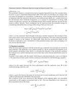
As an example, figure 5 shows the positional workspace of the structures presented in
figures 2a, 2b and 3, with their projections on the coordinate planes for visual convenience.
Figure 6 shows their -orientation workspaces for a few different values of .
a) WiRo-6.1
b)
WiRo-4.3
c)
WiRo-6.3
Fig. 5. Positional workspace of the three structures considered.
a) WiRo-6.1, =10° b) WiRo-6.1, =20° c) WiRo-4.3, =10°
d) WiRo-6.3, =10° e) WiRo-6.3, =20° f) WiRo-6.3, =30°
Fig. 6. -orientation workspaces of the three structures for different values of .
The geometric dimensions of the three structures have been set using arbitrary units,
making them scalable. Obviously though, a rigorous method to compare the results is
needed and it must be independent from the size and proportions of the structures.
Three dimensionless indexes have been proposed (Ferraresi et al., 2001) in order to analyse
the results in a quantitative and objective way. They are the index of volume, the index of
compactness and the index of anisotropy. The index of volume I
v
evaluates the volume of
the workspace relatively to the overall dimension of the robotic structure. The index of
compactness I
c
is the ratio of the workspace volume to the volume of the parallelepiped
circumscribed to it. The index of anisotropy I
a
evaluates the distortion of the workspace with
Cabledrivendevicesfortelemanipulation 179
where
J
~
is the pseudoinverse of
J
~
.
The generic solution of equation (7) is given by:
*
min
τττ
(10)
where
τ * must belong to the kernel, or null space of J
~
, defined through the expression:
0*
~
τJ
(11)
If
J
~
is not square, like in this case, the number of solutions of (7) is ∞
m-6
. This means that the
infinite possible values of
τ can be found by adding to τ
min
a vector τ * that does not affect
the resulting wrench, but can conveniently change the actuator forces.
Condition (8) may be met for a particular six-dimensional point of the workspace if at least
one strictly positive
τ * exists. In this way, knowing that all the multiples of that τ * must
also belong to the null space of
J
~
, it is possible to find an appropriate positive multiplier c
able to compensate any negative component of
τ
min
:
*)(
~
min
ττJf c
(12)
where, as said above:
0* );
~
(*
min
ττJτ cNullc
(13)
Having defined a convenient procedure to evaluate if a particular six-dimensional point
belongs to the theoretical workspace, it is now possible to apply it to a discretised volume. It
is not trivial to find out whether at least one strictly positive τ* exists, especially for highly
redundant structures; a possible method has been developed by the authors (Ferraresi et al.,
2007) but its description is beyond the scopes of this Chapter and will not be presented here.
Moreover, several strategies may be adopted to minimise calculation times and to deal with
displacements and orientations of the platform. In fact, since workspaces are six-
dimensional sets it is not simple to represent them graphically. In order to obtain a
convenient graphical representation, a possible choice is to consider separately the
orientation and position degrees of freedom by distinguishing the positional workspace from
the -orientation workspace.
The positional workspace is the set of platform positions belonging to the workspace with
the platform parallel to the bases. The -orientation workspace is the set of platform
positions that belong to the workspace for each of the possible platform rotations of an angle
± around each of its three reference axes. With those definitions, both the positional and the
-orientation workspaces are three-dimensional sets.
As an example, figure 5 shows the positional workspace of the structures presented in
figures 2a, 2b and 3, with their projections on the coordinate planes for visual convenience.
Figure 6 shows their -orientation workspaces for a few different values of .
a) WiRo-6.1
b)
WiRo-4.3
c)
WiRo-6.3
Fig. 5. Positional workspace of the three structures considered.
a) WiRo-6.1, =10° b) WiRo-6.1, =20° c) WiRo-4.3, =10°
d) WiRo-6.3, =10° e) WiRo-6.3, =20° f) WiRo-6.3, =30°
Fig. 6. -orientation workspaces of the three structures for different values of .
The geometric dimensions of the three structures have been set using arbitrary units,
making them scalable. Obviously though, a rigorous method to compare the results is
needed and it must be independent from the size and proportions of the structures.
Three dimensionless indexes have been proposed (Ferraresi et al., 2001) in order to analyse
the results in a quantitative and objective way. They are the index of volume, the index of
compactness and the index of anisotropy. The index of volume I
v
evaluates the volume of
the workspace relatively to the overall dimension of the robotic structure. The index of
compactness I
c
is the ratio of the workspace volume to the volume of the parallelepiped
circumscribed to it. The index of anisotropy I
a
evaluates the distortion of the workspace with
RemoteandTelerobotics180
respect to the cube with edge equal to the average of the edges of the parallelepiped.
The mathematical expressions for those indexes are:
m
cmbmam
I
abc
zyxp
I
Dh
zyxp
I
ac
cccc
v
4
2
(14)
where p is the quantity of discrete points contained into the workspace, x
, y , z are the
discretisation steps used along their respective axes, D
cc
and h
cc
are the base diameter and
height of the smallest cylinder containing the whole structure, a, b, c are the edges of the
parallelepiped circumscribed to the workspace, and m is the average of a, b and c.
An optimal workspace should have large indexes of volume and compactness, and an index
of anisotropy as close as possible to zero. As an example, these three indexes can be used to
compare the workspaces of the three devices considered above, shown in figures 5 and 6.
Structure
I
v
I
c
I
a
WiRo-6.1 0° 0.07 0.26 1.1
10° 0.02 0.35 2
20° 0.006 0.34 2.5
30°
0.0004
0.28 3.2
WiRo-4.3 0° 0.04 0.18 1.3
10° 0.007 0.23 1
20° 0 0 NaN
WiRo-6.3 0° 0.31 0.4 0.17
10° 0.24 0.34 0.24
20° 0.18 0.3 0.36
30°
0.06 0.3 0.85
Table 1. Application of volume, compactness and anisotropy indexes to the three structures.
Comparing figures 5 and 6, the different performance of the structures in terms of
workspaces is evident. Table 1, thanks to the three indexes, provides a more rigorous
support for the comparative evaluation of different devices.
4. Force reflection
Any cable-driven structure of the kind presented in Section 2 may be used as an active
robot, installing an end effector on the platform and controlling its pose through the
imposition of cable lengths. However, on the contrary, it may also work as a master device
for teleoperation: for this, a handle or similar object must be integrated on the platform to
allow command by an operator. In this case the user determines the pose of the platform
which in turn constrains the theoretical cable lengths.
To avoid any cable to be loose, all of them must be continuously provided with a pulling
force greater than zero; moreover, it is not enough to provide a constant tensioning force to
each cable because, due to their different orientations, the resulting wrench on the platform
might greatly disturb the user’s operation.
So, apart from peculiar cases of little interest here, every cable must be actuated by winding
it to a spool integral to a rotary motor shaft, or directly attached to a linear motor or any
other convenient actuation source.
Since the aim is controlling the resultant wrench on the platform, each actuator pulling a
cable must be force- or torque-controlled (opposed to the case of an active robot, where the
control imposes positions and velocities and forces and torques come as a consequence).
Through a convenient set of cable tensions it is possible to impose any desired wrench on
the platform and, finally, on the user’s hand. The first, intuitive choice could be setting to
zero all forces and torques acting on the platform, to permit the user an unhampered
freedom of movement. However, it is more interesting to provide the device with force
reflection capabilities.
The presence of force reflection in a teleoperation device gives the operator a direct feeling
(possibly scaled) of the task being performed by the slave device. In this way, effectiveness
of operation improves greatly, because the operator can react more promptly to the stimuli
received through the sense of touch than if he had only visual information, even if plentiful
(direct eye contact, displays, led indicators, alarms, etc.). For example, it is not immediate to
perceive the excessive weight of a remotely manipulated object, or a contact force
unexpectedly high, using only indirect information; when the alarm buzzes, or the display
starts flashing, it might already be too late. On the contrary, if forces and torques are directly
reflected to the operator, he might act before reaching critical situations. The same applies
for small-scale teleoperation, e.g. remote surgery: excessive forces may have terrible
consequences.
Equations (12) and (13) guarantee that it is theoretically possible to give the platform any
desired wrench, if its current pose belongs to the theoretical workspace.
Statics relates the cable forces to the six-dimensional wrench on the platform, according to
equation (7). For a nine-cable structure it can be interpreted as follows: given a vector
6
Rf
that is desired to act on the platform as a force reflection, it is necessary to find a vector of
cable forces
9
Rτ fulfilling equation (7). Due to the redundancy of the structure, if
9x6
~
RJ
has a full rank equal to 6, the set of vector fulfilling equation (7) is a three-dimensional
hypersurface in a nine-dimensional Euclidean space, meaning that the number of solutions
is ∞
3
.
Among all possible solutions, the one reckoned optimal may be chosen through the
following considerations. Once a minimum admissible cable tension
τ
adm
has been set, every
component of
τ must be greater than or equal to that value, while at the same time keeping
them as low as possible and still fulfilling equation (7).
Therefore the following target may be written:
9
1
minimize
i
i
G
(15)
under the conditions:
Cabledrivendevicesfortelemanipulation 181
respect to the cube with edge equal to the average of the edges of the parallelepiped.
The mathematical expressions for those indexes are:
m
cmbmam
I
abc
zyxp
I
Dh
zyxp
I
ac
cccc
v
4
2
(14)
where p is the quantity of discrete points contained into the workspace, x
, y
, z are the
discretisation steps used along their respective axes, D
cc
and h
cc
are the base diameter and
height of the smallest cylinder containing the whole structure, a, b, c are the edges of the
parallelepiped circumscribed to the workspace, and m is the average of a, b and c.
An optimal workspace should have large indexes of volume and compactness, and an index
of anisotropy as close as possible to zero. As an example, these three indexes can be used to
compare the workspaces of the three devices considered above, shown in figures 5 and 6.
Structure
I
v
I
c
I
a
WiRo-6.1 0° 0.07 0.26 1.1
10° 0.02 0.35 2
20° 0.006 0.34 2.5
30°
0.0004
0.28 3.2
WiRo-4.3 0° 0.04 0.18 1.3
10° 0.007 0.23 1
20° 0 0 NaN
WiRo-6.3 0° 0.31 0.4 0.17
10° 0.24 0.34 0.24
20° 0.18 0.3 0.36
30°
0.06 0.3 0.85
Table 1. Application of volume, compactness and anisotropy indexes to the three structures.
Comparing figures 5 and 6, the different performance of the structures in terms of
workspaces is evident. Table 1, thanks to the three indexes, provides a more rigorous
support for the comparative evaluation of different devices.
4. Force reflection
Any cable-driven structure of the kind presented in Section 2 may be used as an active
robot, installing an end effector on the platform and controlling its pose through the
imposition of cable lengths. However, on the contrary, it may also work as a master device
for teleoperation: for this, a handle or similar object must be integrated on the platform to
allow command by an operator. In this case the user determines the pose of the platform
which in turn constrains the theoretical cable lengths.
To avoid any cable to be loose, all of them must be continuously provided with a pulling
force greater than zero; moreover, it is not enough to provide a constant tensioning force to
each cable because, due to their different orientations, the resulting wrench on the platform
might greatly disturb the user’s operation.
So, apart from peculiar cases of little interest here, every cable must be actuated by winding
it to a spool integral to a rotary motor shaft, or directly attached to a linear motor or any
other convenient actuation source.
Since the aim is controlling the resultant wrench on the platform, each actuator pulling a
cable must be force- or torque-controlled (opposed to the case of an active robot, where the
control imposes positions and velocities and forces and torques come as a consequence).
Through a convenient set of cable tensions it is possible to impose any desired wrench on
the platform and, finally, on the user’s hand. The first, intuitive choice could be setting to
zero all forces and torques acting on the platform, to permit the user an unhampered
freedom of movement. However, it is more interesting to provide the device with force
reflection capabilities.
The presence of force reflection in a teleoperation device gives the operator a direct feeling
(possibly scaled) of the task being performed by the slave device. In this way, effectiveness
of operation improves greatly, because the operator can react more promptly to the stimuli
received through the sense of touch than if he had only visual information, even if plentiful
(direct eye contact, displays, led indicators, alarms, etc.). For example, it is not immediate to
perceive the excessive weight of a remotely manipulated object, or a contact force
unexpectedly high, using only indirect information; when the alarm buzzes, or the display
starts flashing, it might already be too late. On the contrary, if forces and torques are directly
reflected to the operator, he might act before reaching critical situations. The same applies
for small-scale teleoperation, e.g. remote surgery: excessive forces may have terrible
consequences.
Equations (12) and (13) guarantee that it is theoretically possible to give the platform any
desired wrench, if its current pose belongs to the theoretical workspace.
Statics relates the cable forces to the six-dimensional wrench on the platform, according to
equation (7). For a nine-cable structure it can be interpreted as follows: given a vector
6
Rf
that is desired to act on the platform as a force reflection, it is necessary to find a vector of
cable forces
9
Rτ fulfilling equation (7). Due to the redundancy of the structure, if
9x6
~
RJ
has a full rank equal to 6, the set of vector fulfilling equation (7) is a three-dimensional
hypersurface in a nine-dimensional Euclidean space, meaning that the number of solutions
is ∞
3
.
Among all possible solutions, the one reckoned optimal may be chosen through the
following considerations. Once a minimum admissible cable tension
τ
adm
has been set, every
component of
τ must be greater than or equal to that value, while at the same time keeping
them as low as possible and still fulfilling equation (7).
Therefore the following target may be written:
9
1
minimize
i
i
G
(15)
under the conditions:
RemoteandTelerobotics182
9 1
~
i
admi
fτJ
(16)
That is a linear programming problem that may be solved, for instance, by using the simplex
method. The solution to the problem (15), (16) leads to an optimised and internally
connected
τ, i.e. it can be demonstrated that if f and J
~
vary continuously, then also the
solution
τ calculated instant by instant presents a continuous run against time.
The procedure to identify the theoretical workspace does not take into account the
interaction of the structure with the environment, in terms of maximum forces and torques
acting on the platform, and the maximum tension each cable can exert. Therefore a further,
different definition of workspace is necessary, involving those considerations. The portion
of theoretical workspace where the structure can provide the desired wrench with
acceptable cable tensions is called
effective workspace.
In detail, to find that out, the following parameters must be set: maximum force on the
operator’s hand in any direction, maximum torque around any axis, minimum and
maximum admissible values of cable tension. Then, for every pose in the theoretical
workspace, maximum forces and torques must be applied in different directions. For every
pose, the cable tensions must be calculated according to the problem (15), (16), recording the
largest value of cable tension. In this way, every pose of the platform is characterised by a
maximum cable tension resulting from the application of the maximum wrench. This value
can be compared to the maximum admissible one, determining whether or not that
particular pose belongs to the effective workspace.
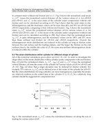
As an example, figure 7 shows in graphical form a few results created applying that
procedure to the WiRo-6.3, for a given set of parameters (maximum force on the operator’s
hand in any direction: 10N, maximum torque around any axis: 1Nm, minimum admissible
value of cable tension: 5N, maximum value of cable tension: 150N). For the sake of graphical
representation, the workspace has been cross sectioned at various values of
z; the base plane
represents the platform centre position on that cross section, while the dimension on the
third axis and the colour intensity represent the cable tension magnitude.
After a complete scan of the workspace, the result is – in this particular case – that the
effective workspace is a wide subset of the theoretical one, making it possible to construct a
structure with the physical characteristics that have been chosen as parameters. On the other
hand, it must be noted that towards the borders of the workspace the maximum tensions
increase dramatically, resulting one or even two orders of magnitude greater than in the
central portion. Therefore, possible misuse of the structure taking the platform in one of
those conditions must be carefully avoided; otherwise cable tensions and forces on the
operator’s hand can literally become uncontrollable. Obviously, the same should be done
for orientations which, in the examples considered here, must be limited to ±30° around any
axis (a greater angle would dramatically reduce the available orientation workspace shown
in figure 6). A possible strategy can be generating a strong opposing force (or torque) when
the operator tries to move (or rotate) the platform across the border of the effective
workspace, thus limiting its freedom of movement “virtually”, i.e. without the use of
physical end-of-run stop devices.
a) Maximum tensions at z
=
-20
b) Maximum tensions at z
= -50
c) Representation of effective (black) vs. theoretical
(black + grey) workspace
at z = -20
d) Representation of effective (black) vs. theoretical
(black + grey) workspace
at z = -50
Fig. 7. a), b) Example cross sections of the workspace showing maximum cable tensions. c),
d) The same cross sections shown to underline the distinction between theoretical and
effective workspace.
5. Device control and cable actuation
The control logic is summarized in figure 8. The operator imposes position and velocity to a
proper element, which may be a handle or some other device, suspended in space by the
cables. Each cable is tensioned by a specific actuator and under the operator’s action it can
vary its length between the fixed and moving points (indicated as
P
Fi
and P
Mi
in figure 1).
Measuring the length of each cable through transducers, the control system is able to
evaluate position, orientation, linear and angular velocity of the handle by means of the
forward kinematics algorithm. Those results are used as reference input to the control
Cabledrivendevicesfortelemanipulation 183
9 1
~
i
admi
fτJ
(16)
That is a linear programming problem that may be solved, for instance, by using the simplex
method. The solution to the problem (15), (16) leads to an optimised and internally
connected
τ, i.e. it can be demonstrated that if f and J
~
vary continuously, then also the
solution
τ calculated instant by instant presents a continuous run against time.
The procedure to identify the theoretical workspace does not take into account the
interaction of the structure with the environment, in terms of maximum forces and torques
acting on the platform, and the maximum tension each cable can exert. Therefore a further,
different definition of workspace is necessary, involving those considerations. The portion
of theoretical workspace where the structure can provide the desired wrench with
acceptable cable tensions is called
effective workspace.
In detail, to find that out, the following parameters must be set: maximum force on the
operator’s hand in any direction, maximum torque around any axis, minimum and
maximum admissible values of cable tension. Then, for every pose in the theoretical
workspace, maximum forces and torques must be applied in different directions. For every
pose, the cable tensions must be calculated according to the problem (15), (16), recording the
largest value of cable tension. In this way, every pose of the platform is characterised by a
maximum cable tension resulting from the application of the maximum wrench. This value
can be compared to the maximum admissible one, determining whether or not that
particular pose belongs to the effective workspace.
As an example, figure 7 shows in graphical form a few results created applying that
procedure to the WiRo-6.3, for a given set of parameters (maximum force on the operator’s
hand in any direction: 10N, maximum torque around any axis: 1Nm, minimum admissible
value of cable tension: 5N, maximum value of cable tension: 150N). For the sake of graphical
representation, the workspace has been cross sectioned at various values of
z; the base plane
represents the platform centre position on that cross section, while the dimension on the
third axis and the colour intensity represent the cable tension magnitude.
After a complete scan of the workspace, the result is – in this particular case – that the
effective workspace is a wide subset of the theoretical one, making it possible to construct a
structure with the physical characteristics that have been chosen as parameters. On the other
hand, it must be noted that towards the borders of the workspace the maximum tensions
increase dramatically, resulting one or even two orders of magnitude greater than in the
central portion. Therefore, possible misuse of the structure taking the platform in one of
those conditions must be carefully avoided; otherwise cable tensions and forces on the
operator’s hand can literally become uncontrollable. Obviously, the same should be done
for orientations which, in the examples considered here, must be limited to ±30° around any
axis (a greater angle would dramatically reduce the available orientation workspace shown
in figure 6). A possible strategy can be generating a strong opposing force (or torque) when
the operator tries to move (or rotate) the platform across the border of the effective
workspace, thus limiting its freedom of movement “virtually”, i.e. without the use of
physical end-of-run stop devices.
a) Maximum tensions at z
=
-20
b) Maximum tensions at z
= -50
c) Representation of effective (black) vs. theoretical
(black + grey) workspace
at z = -20
d) Representation of effective (black) vs. theoretical
(black + grey) workspace
at z = -50
Fig. 7. a), b) Example cross sections of the workspace showing maximum cable tensions. c),
d) The same cross sections shown to underline the distinction between theoretical and
effective workspace.
5. Device control and cable actuation
The control logic is summarized in figure 8. The operator imposes position and velocity to a
proper element, which may be a handle or some other device, suspended in space by the
cables. Each cable is tensioned by a specific actuator and under the operator’s action it can
vary its length between the fixed and moving points (indicated as
P
Fi
and P
Mi
in figure 1).
Measuring the length of each cable through transducers, the control system is able to
evaluate position, orientation, linear and angular velocity of the handle by means of the
forward kinematics algorithm. Those results are used as reference input to the control
RemoteandTelerobotics184
system of the slave robot actuators: the slave unit is therefore driven to carry out a particular
task.
As a consequence, interaction forces are exerted on the slave unit by the environment; such
forces may be measured by convenient sensors and reproduced on the operator’s handle.
The global environment forces are therefore used as reference input to the control system.
The latter can calculate the exact force that each cable must exert on the handle by means of
the inverse statics algorithm; this value is therefore used as reference input to each cable
actuator.
The control system may apply a scale factor both to the movement of the slave unit and to
the forces reflected to the operator.
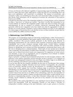
Fig. 8. The control logic of a telemanipulation system with a cable driven haptic master
The control system must perform a double function:
(a)
on the basis of the cable lengths it must calculate the pose of the platform; since the
master has a parallel structure (that may be also multi-redundant), this real-time
calculation can be very demanding;
(b)
a convenient sensorial system should read the wrench exerted by the environment on
the remote slave unit; such six-degree-of-freedom information is used by the control
system to calculate, by means of an inverse statics algorithm, the exact value of each
cable tension; again, the single or multiple redundancy of the parallel cable structure
makes real-time operation particularly demanding.
The accuracy of the control depends on the physical characteristics of the device, in
particular the mechanical layout and how the control system interacts with the cables and
their actuators.
The two main functions of the control system (master pose calculation and cable tension
generation) may be affected by certain errors, which can compromise the effectiveness of the
device.
Forward
kinematics
Cables
Operator
Cable
actuators
Length
transducers
Inverse
statics
Environment
Slave Unit
Cable
len
g
ths
Cable tensions
Control System
Slave
drivers
Position /
Velocit
y
Environment forces
Force
sensors
Visual feedback
Command
Command
Position /
Velocity
Platform
Force
reflection
Forces
Master
Unit
In particular, the kinematical accuracy is strictly related with the characteristics of the cables
and their path. The path of each cable can be described considering two different sections,
starting from the mobile platform where one end is attached. The first is called the
free
section
of the cable, since its direction and its length are determined by the platform motion.
The cable passes through a given point on the structure corresponding theoretically to a
fixed point. The variable lengths of the free section of each cable are used to calculate the
platform pose. The second section of the cable goes from the cited fixed point to the
actuation group and has an ideally constant length.
The way to realize the passage through the fixed point is crucial for the geometric accuracy
of the system.
Figure 9 shows a possible way to realize a fixed passing point of the cable. The cable is
conveyed into a cylindrical nylon insert whose entrance hole represents the theoretical
passing point and then it is diverted by the pulley towards the actuator.
Fig. 9. Realization of a fixed passing point for the cable using a low-friction insert
Fig. 10. Realisation of a fixed passing point for the cable using skew rollers.
fixed point
towards
platform
towards
actuation
towards
platform
towards
actuation
fixed point
Cabledrivendevicesfortelemanipulation 185
system of the slave robot actuators: the slave unit is therefore driven to carry out a particular
task.
As a consequence, interaction forces are exerted on the slave unit by the environment; such
forces may be measured by convenient sensors and reproduced on the operator’s handle.
The global environment forces are therefore used as reference input to the control system.
The latter can calculate the exact force that each cable must exert on the handle by means of
the inverse statics algorithm; this value is therefore used as reference input to each cable
actuator.
The control system may apply a scale factor both to the movement of the slave unit and to
the forces reflected to the operator.
Fig. 8. The control logic of a telemanipulation system with a cable driven haptic master
The control system must perform a double function:
(a)
on the basis of the cable lengths it must calculate the pose of the platform; since the
master has a parallel structure (that may be also multi-redundant), this real-time
calculation can be very demanding;
(b)
a convenient sensorial system should read the wrench exerted by the environment on
the remote slave unit; such six-degree-of-freedom information is used by the control
system to calculate, by means of an inverse statics algorithm, the exact value of each
cable tension; again, the single or multiple redundancy of the parallel cable structure
makes real-time operation particularly demanding.
The accuracy of the control depends on the physical characteristics of the device, in
particular the mechanical layout and how the control system interacts with the cables and
their actuators.
The two main functions of the control system (master pose calculation and cable tension
generation) may be affected by certain errors, which can compromise the effectiveness of the
device.
Forward
kinematics
Cables
Operator
Cable
actuators
Length
transducers
Inverse
statics
Environment
Slave Unit
Cable
len
g
ths
Cable tensions
Control System
Slave
drivers
Position /
Velocit
y
Environment forces
Force
sensors
Visual feedback
Command
Command
Position /
Velocity
Platform
Force
reflection
Forces
Master
Unit
In particular, the kinematical accuracy is strictly related with the characteristics of the cables
and their path. The path of each cable can be described considering two different sections,
starting from the mobile platform where one end is attached. The first is called the
free
section
of the cable, since its direction and its length are determined by the platform motion.
The cable passes through a given point on the structure corresponding theoretically to a
fixed point. The variable lengths of the free section of each cable are used to calculate the
platform pose. The second section of the cable goes from the cited fixed point to the
actuation group and has an ideally constant length.
The way to realize the passage through the fixed point is crucial for the geometric accuracy
of the system.
Figure 9 shows a possible way to realize a fixed passing point of the cable. The cable is
conveyed into a cylindrical nylon insert whose entrance hole represents the theoretical
passing point and then it is diverted by the pulley towards the actuator.
Fig. 9. Realization of a fixed passing point for the cable using a low-friction insert
Fig. 10. Realisation of a fixed passing point for the cable using skew rollers.
fixed point
towards
platform
towards
actuation
towards
platform
towards
actuation
fixed point
RemoteandTelerobotics186
Another possible solution is shown in figure 10. The cable coming from the platform is
diverted by a pair of skew rollers mounted perpendicularly, and then follows the second
part of the path defined by fixed pulleys.
Due to the physical characteristics of cables and diversion system, during the handle motion
the end of the cable free section is not actually fixed, but moves in a given range,
introducing an error in the calculation of the platform pose. For instance, the solution of
figure 10 is less accurate than the former one but greatly reduces friction, producing a
considerable advantage as will be explained later.
In an ideal situation, each cable should be inextensible and perfectly flexible; as a matter of
fact, tensile load causes deformation and flexural stiffness makes sure that the theoretical
passing point actually corresponds to a small area. To limit such drawbacks it is necessary to
choose cables with convenient characteristics. In particular, a good choice may be adoption
of synthetic fibre cables, such as Dyneema
®
(Hoppe, 1997). In comparison with steel wires of
the same strength, those cables are much more flexible and just slightly more extensible,
while presenting a similar cross section.
The greater flexibility reduces drastically the extension of the passing area, which can
reasonably be approximated to a point.
Moreover, the longitudinal compliance of Dyneema cables is comparable with steel cables
but, although non-linear, presents a much more regular run, thus allowing compensating
the length variation with a convenient relation as a function of cable tension.
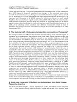
Fig. 11. Mechanical characteristic of a Dyneema-140 cable
As an example, figure 11 shows the mechanical characteristic of a Dyneema-140 cable. This
characteristic allows calculating a simple function yielding the percentage elongation (
E) as
a function of the tensile force (F) expressed in N:
FE 0177.034.253.1
(17)
Force [N]
Elongation [%]
The non-linearity of the cable characteristic can also be exploited as an advantage. As can be
seen in figure 11, such a stiffening run allows to make the whole structure more rigid by
properly increasing the minimum tension
τ
adm
in the conditions (16), thus producing an
advantage for the system controllability.
A further advantage of great cable flexibility is the simplicity of realising the attachment to
the platform: this can be realized by a simple knot, practically reducing the attach area to a
virtual point fixed to the handle.
As regards the fixed-length part of the cable, it covers a path from the fixed point to the
actuator. It is important that the cable constraints are as rigid as possible; therefore the cable
should preferably be guided by pulleys rather than a flexible sheath which may be
longitudinally compliant.
Another peculiarity of haptic teleoperation systems is the fact that the accuracy of the master
pose calculation is less important than that required for the force reflection on the operator’s
hand.
This is in analogy with actions effected directly by a human subject: the approach and
positioning of the hand is controlled by the human proprioceptive (i.e. self-sensing,
detecting the motion or position of the body or a limb) and visual system, relatively rough,
while the completion of the operation, however accurate, is controlled by tactile forces.
The generation of the wrench on the operator’s hand is therefore a very critical point, which
requires great accuracy and must compensate various disturbances.
Friction must be avoided or limited as much as possible. Effective software compensation by
means of an algorithm that considers the sliding direction and velocity of seven or more
cables is practically impossible due to irregular behaviour and most of all to the
discontinuity around zero velocity. That is a further reason in favour of realising the cable
path along the fixed-length part using pulleys and low friction bearings rather than a
flexible sheath.
Friction may be present not only in the cable path, but also inside the actuators. Therefore
their choice is a very strategic point. Generally, two main options are available: (a) electric
motors; (b) pneumatic actuators.
The most common solution in this kind of application is the adoption of electric motors, but
this choice is somehow disputable: the actuators must operate around the stall condition, so
they may have difficulties in controlling accurately the torque value.
A typical drawback arises when using brushless motors, characterized by a more or less
evident
cogging torque, i.e. a variation in torque depending on the rotor angular position. In
some cases such variation can amount to 10% of the total torque.
Moreover, a rotating motor requires a given device to transform its motion into linear, for
example a spool on the shaft. On the other hand, an electric motor presents a very high
dynamics, thus allowing an effective control of the cable tension during the handle motion.
An effective alternative is represented by pneumatic actuators. This technology may give
interesting advantages, but several aspects need to be accurately considered and evaluated
(Ferraresi et al., 2006)
Force control is apparently simpler, since this is obtained by controlling the air pressure in
the chambers of a cylinder. Such operation is relatively easy in static condition, but could be
difficult during motion, because of the low dynamics of the overall pneumatic system
(actuator, valves, piping).
Cabledrivendevicesfortelemanipulation 187
Another possible solution is shown in figure 10. The cable coming from the platform is
diverted by a pair of skew rollers mounted perpendicularly, and then follows the second
part of the path defined by fixed pulleys.
Due to the physical characteristics of cables and diversion system, during the handle motion
the end of the cable free section is not actually fixed, but moves in a given range,
introducing an error in the calculation of the platform pose. For instance, the solution of
figure 10 is less accurate than the former one but greatly reduces friction, producing a
considerable advantage as will be explained later.
In an ideal situation, each cable should be inextensible and perfectly flexible; as a matter of
fact, tensile load causes deformation and flexural stiffness makes sure that the theoretical
passing point actually corresponds to a small area. To limit such drawbacks it is necessary to
choose cables with convenient characteristics. In particular, a good choice may be adoption
of synthetic fibre cables, such as Dyneema
®
(Hoppe, 1997). In comparison with steel wires of
the same strength, those cables are much more flexible and just slightly more extensible,
while presenting a similar cross section.
The greater flexibility reduces drastically the extension of the passing area, which can
reasonably be approximated to a point.
Moreover, the longitudinal compliance of Dyneema cables is comparable with steel cables
but, although non-linear, presents a much more regular run, thus allowing compensating
the length variation with a convenient relation as a function of cable tension.
Fig. 11. Mechanical characteristic of a Dyneema-140 cable
As an example, figure 11 shows the mechanical characteristic of a Dyneema-140 cable. This
characteristic allows calculating a simple function yielding the percentage elongation (
E) as
a function of the tensile force (F) expressed in N:
FE
0177.034.253.1
(17)
Force [N]
Elongation [%]
The non-linearity of the cable characteristic can also be exploited as an advantage. As can be
seen in figure 11, such a stiffening run allows to make the whole structure more rigid by
properly increasing the minimum tension
τ
adm
in the conditions (16), thus producing an
advantage for the system controllability.
A further advantage of great cable flexibility is the simplicity of realising the attachment to
the platform: this can be realized by a simple knot, practically reducing the attach area to a
virtual point fixed to the handle.
As regards the fixed-length part of the cable, it covers a path from the fixed point to the
actuator. It is important that the cable constraints are as rigid as possible; therefore the cable
should preferably be guided by pulleys rather than a flexible sheath which may be
longitudinally compliant.
Another peculiarity of haptic teleoperation systems is the fact that the accuracy of the master
pose calculation is less important than that required for the force reflection on the operator’s
hand.
This is in analogy with actions effected directly by a human subject: the approach and
positioning of the hand is controlled by the human proprioceptive (i.e. self-sensing,
detecting the motion or position of the body or a limb) and visual system, relatively rough,
while the completion of the operation, however accurate, is controlled by tactile forces.
The generation of the wrench on the operator’s hand is therefore a very critical point, which
requires great accuracy and must compensate various disturbances.
Friction must be avoided or limited as much as possible. Effective software compensation by
means of an algorithm that considers the sliding direction and velocity of seven or more
cables is practically impossible due to irregular behaviour and most of all to the
discontinuity around zero velocity. That is a further reason in favour of realising the cable
path along the fixed-length part using pulleys and low friction bearings rather than a
flexible sheath.
Friction may be present not only in the cable path, but also inside the actuators. Therefore
their choice is a very strategic point. Generally, two main options are available: (a) electric
motors; (b) pneumatic actuators.
The most common solution in this kind of application is the adoption of electric motors, but
this choice is somehow disputable: the actuators must operate around the stall condition, so
they may have difficulties in controlling accurately the torque value.
A typical drawback arises when using brushless motors, characterized by a more or less
evident
cogging torque, i.e. a variation in torque depending on the rotor angular position. In
some cases such variation can amount to 10% of the total torque.
Moreover, a rotating motor requires a given device to transform its motion into linear, for
example a spool on the shaft. On the other hand, an electric motor presents a very high
dynamics, thus allowing an effective control of the cable tension during the handle motion.
An effective alternative is represented by pneumatic actuators. This technology may give
interesting advantages, but several aspects need to be accurately considered and evaluated
(Ferraresi et al., 2006)
Force control is apparently simpler, since this is obtained by controlling the air pressure in
the chambers of a cylinder. Such operation is relatively easy in static condition, but could be
difficult during motion, because of the low dynamics of the overall pneumatic system
(actuator, valves, piping).