CCNA Exploration _part5 potx
Bạn đang xem bản rút gọn của tài liệu. Xem và tải ngay bản đầy đủ của tài liệu tại đây (602.06 KB, 30 trang )
CCNA Exploration
Routing Protocols and Concepts: RIP version 1 Lab 5.6.3: RIP Troubleshooting
• Discover where convergence is not complete.
• Gather information about the non-converged portion of the network along with any other errors.
• Analyze information to determine why convergence is not complete.
• Propose solutions to network errors.
• Implement solutions to network errors.
• Document the corrected network.
Scenario
In this lab, you will begin by loading configuration scripts on each of the routers. These scripts contain
errors that will prevent end-to-end communication across the network. You will need to troubleshoot each
router to determine the configuration errors and then use the appropriate commands to correct the
configurations. When you have corrected all of the configuration errors, all of the hosts on the network
should be able to communicate with each other.
The network should also have the following requirements met:
• RIPv1 routing is configured on the BRANCH router.
• RIPv1 routing is configured on the HQ router.
• RIP updates must be disabled on the BRANCH and HQ LAN interfaces.
• Static default route is configured on the HQ router and shared with the BRANCH router via RIP
updates.
• Static routes for all HQ and BRANCH networks are to be configured on the ISP router. The routes
must be summarized wherever possible.
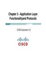
Task 1: Cable, Erase, and Reload the Routers.
Step 1: Cable a network.
Cable a network that is similar to the one in the Topology Diagram.
Step 2: Clear the configuration on each router.
Clear the configuration on each of routers using the erase startup-config command and then
reload the routers. Answer no if asked to save changes.
Task 2: Load Routers with the Supplied Scripts.
Step 1: Load the following script onto the BRANCH router.
hostname BRANCH
!
no ip domain-lookup
!
interface FastEthernet0/0
ip address 192.168.1.1 255.255.255.0
duplex auto
speed auto
!
interface Serial0/0/0
ip address 10.45.1.254 255.255.255.0
clock rate 64000
no shutdown
!
router rip
All contents are Copyright © 1992–2007 Cisco Systems, Inc. All rights reserved. This document is Cisco Public Information. Page 2 of 11
This is trial version
www.adultpdf.com
CCNA Exploration
Routing Protocols and Concepts: RIP version 1 Lab 5.6.3: RIP Troubleshooting
passive-interface FastEthernet0/0
network 10.0.0.0
!
line con 0
line vty 0 4
password cisco
login
!
end
Step 2: Load the following script onto the HQ router.
hostname HQ
!
no ip domain-lookup
!
interface FastEthernet0/0
ip address 10.45.2.1 255.255.255.0
duplex auto
speed auto
no shutdown
!
interface Serial0/0/0
ip address 10.45.1.1 255.255.255.0
no shutdown
!
interface Serial0/0/1
ip address 172.20.20.254 255.255.255.0
clock rate 64000
no shutdown
!
router rip
passive-interface FastEthernet0/0
network 10.0.0.0
!
ip route 0.0.0.0 0.0.0.0 Serial0/0/1
!
line con 0
line vty 0 4
password cisco
login
!
end
Step 3: Load the following script onto the ISP router.
hostname ISP
!
no ip domain-lookup
!
interface FastEthernet0/0
ip address 172.16.1.1 255.255.255.0
duplex auto
speed auto
All contents are Copyright © 1992–2007 Cisco Systems, Inc. All rights reserved. This document is Cisco Public Information. Page 3 of 11
This is trial version
www.adultpdf.com
CCNA Exploration
Routing Protocols and Concepts: RIP version 1 Lab 5.6.3: RIP Troubleshooting
no shutdown
!
interface Serial0/0/1
ip address 172.20.20.1 255.255.255.0
no shutdown
!
ip route 10.45.0.0 255.255.254.0 Serial0/0/1
ip route 192.168.1.0 255.255.255.0 Serial0/0/1
!
line con 0
line vty 0 4
password cisco
login
!
end
Task 3: Troubleshoot the BRANCH Router
Step 1: Begin troubleshooting at the Host connected to the BRANCH router.
From the host PC1, is it possible to ping PC2? _________
From the host PC1, is it possible to ping PC3? _________
From the host PC1, is it possible to ping the default gateway? _________
Step 2: Examine the BRANCH router to find possible configuration errors.
Begin by viewing the summary of status information for each interface on the router.
Are there any problems with the status of the interfaces?
_________________________________________________________________________________
_________________________________________________________________________________
________________________________________________________________________________
If there are any problems with the status of the interfaces, record any commands that will be necessary to
correct the configuration errors.
___________________________________________________________________________________
___________________________________________________________________________________
___________________________________________________________________________________
Step 3: If you have recorded any commands above, apply them to the router configuration now.
Step 4: View summary of the status information.
If any changes were made to the configuration in the previous step, view the summary of the status
information for the router interfaces again.
Does the information in the interface status summary indicate any configuration errors? _________
If the answer is yes, troubleshoot the interface status of the interfaces again.
All contents are Copyright © 1992–2007 Cisco Systems, Inc. All rights reserved. This document is Cisco Public Information. Page 4 of 11
This is trial version
www.adultpdf.com
CCNA Exploration
Routing Protocols and Concepts: RIP version 1 Lab 5.6.3: RIP Troubleshooting
Step 5: Troubleshoot the routing configuration on the BRANCH router.
What networks are shown in the routing table?
___________________________________________________________________________________
___________________________________________________________________________________
___________________________________________________________________________________
Are there any problems with the routing table?
___________________________________________________________________________________
___________________________________________________________________________________
___________________________________________________________________________________
If there are any problems with the routing table, record any commands that will be necessary to correct
the configuration errors.
___________________________________________________________________________________
___________________________________________________________________________________
____________________________________________________________________________________
What networks are included in the RIP updates?
___________________________________________________________________________________
___________________________________________________________________________________
____________________________________________________________________________________
Are there any problems with the RIP updates that are being sent out from the router?
___________________________________________________________________________________
___________________________________________________________________________________
___________________________________________________________________________________
If there are any problems with the RIP configuration, record any commands that will be necessary to
correct the configuration errors.
___________________________________________________________________________________
___________________________________________________________________________________
___________________________________________________________________________________
All contents are Copyright © 1992–2007 Cisco Systems, Inc. All rights reserved. This document is Cisco Public Information. Page 5 of 11
This is trial version
www.adultpdf.com
CCNA Exploration
Routing Protocols and Concepts: RIP version 1 Lab 5.6.3: RIP Troubleshooting
Step 6: If you have recorded any commands above, apply them to the router configuration now.
Step 7: View the routing information.
If any changes were made to the configuration in the previous steps, view the routing information again.
Does the information in routing table indicate any configuration errors? __________
Does the information included in the RIP updates that are sent out indicate any configuration errors?
_________
If the answer to either of these questions is yes, troubleshoot the routing configuration again.
What networks are included in the RIP updates?
___________________________________________________________________________________
___________________________________________________________________________________
___________________________________________________________________________________
Step 8: Attempt to ping between the hosts again.
From the host PC1, is it possible to ping PC2? __________
From the host PC1, is it possible to ping PC3? __________
From the host PC1, is it possible to ping the Serial 0/0 interface of the HQ router? __________
Task 4: Troubleshoot the HQ Router
Step 1: Begin troubleshooting at the Host connected to the R2 router.
From the host PC2, is it possible to ping PC1? __________
From the host PC2, is it possible to ping PC3? __________
From the host PC2, is it possible to ping the default gateway? __________
Step 2: Examine the HQ router to find possible configuration errors.
Begin by viewing the summary of status information for each interface on the router.
Are there any problems with the status of the interfaces?
___________________________________________________________________________________
___________________________________________________________________________________
___________________________________________________________________________________
If there are any problems with the status of the interfaces, record any commands that will be necessary to
correct the configuration errors.
___________________________________________________________________________________
___________________________________________________________________________________
___________________________________________________________________________________
All contents are Copyright © 1992–2007 Cisco Systems, Inc. All rights reserved. This document is Cisco Public Information. Page 6 of 11
This is trial version
www.adultpdf.com
CCNA Exploration
Routing Protocols and Concepts: RIP version 1 Lab 5.6.3: RIP Troubleshooting
Step 3: If you have recorded any commands above, apply them to the router configuration now.
Step 4: View the summary of the status information.
If any changes were made to the configuration in the previous step, view the summary of the status
information for the router interfaces again.
Does the information in the interface status summary indicate any configuration errors? _________
If the answer is yes, troubleshoot the interface status of the interfaces again.
Step 5: Troubleshoot the routing configuration on the BRANCH router.
What networks are shown in the routing table?
___________________________________________________________________________________
___________________________________________________________________________________
___________________________________________________________________________________
Are there any problems with the routing table?
___________________________________________________________________________________
___________________________________________________________________________________
___________________________________________________________________________________
If there are any problems with the routing table, record any commands that will be necessary to correct
the configuration errors.
___________________________________________________________________________________
___________________________________________________________________________________
___________________________________________________________________________________
What networks are included in the RIP updates?
___________________________________________________________________________________
___________________________________________________________________________________
___________________________________________________________________________________
Are there any problems with the RIP updates that are being sent out from the router?
___________________________________________________________________________________
___________________________________________________________________________________
___________________________________________________________________________________
All contents are Copyright © 1992–2007 Cisco Systems, Inc. All rights reserved. This document is Cisco Public Information. Page 7 of 11
This is trial version
www.adultpdf.com
CCNA Exploration
Routing Protocols and Concepts: RIP version 1 Lab 5.6.3: RIP Troubleshooting
If there are any problems with the RIP configuration, record any commands that will be necessary to
correct the configuration errors.
___________________________________________________________________________________
___________________________________________________________________________________
___________________________________________________________________________________
___________________________________________________________________________________
Step 6: If you have recorded any commands above, apply them to the router configuration now.
Step 7: View the routing information.
If any changes were made to the configuration in the previous steps, view the routing information again.
Does the information in routing table indicate any configuration errors? ________
Does the information included in the RIP updates that are sent out indicate any configuration errors?
________
If the answer to either of these questions is yes, troubleshoot the routing configuration again.
What networks are included in the RIP updates?
___________________________________________________________________________________
___________________________________________________________________________________
___________________________________________________________________________________
Step 8: Verify that the HQ router is sending a default route to the BRANCH router.
Is there a default route in the BRANCH routing table? _____________
If not, what commands are needed to configure this on the HQ router?
___________________________________________________________________________________
___________________________________________________________________________________
___________________________________________________________________________________
Step 9: If you have recorded any commands above, apply them to the HQ router configuration
now.
Step 10: View the BRANCH routing table.
If any changes were made to the configuration in the previous step, view the BRANCH routing table
again.
Is there a default route in the BRANCH routing table? __________
If the answer is no, troubleshoot the RIP configuration again.
Step 11: Attempt to ping between the hosts again.
From the host PC2, is it possible to ping PC1? _________
All contents are Copyright © 1992–2007 Cisco Systems, Inc. All rights reserved. This document is Cisco Public Information. Page 8 of 11
This is trial version
www.adultpdf.com
CCNA Exploration
Routing Protocols and Concepts: RIP version 1 Lab 5.6.3: RIP Troubleshooting
From the host PC2, is it possible to ping the Serial 0/1 interface of the ISP router? _________
From the host PC1, is it possible to ping PC3? _________
Task 5: Troubleshoot the ISP Router
Step 1: Begin troubleshooting at the Host connected to the ISP router.
From the host PC3, is it possible to ping PC1? __________
From the host PC3, is it possible to ping PC2? __________
From the host PC3, is it possible to ping the default gateway? _________
Step 2: Examine the ISP router to find possible configuration errors.
Begin by viewing the summary of status information for each interface on the router.
Are there any problems with the status of the interfaces?
___________________________________________________________________________________
___________________________________________________________________________________
___________________________________________________________________________________
If there are any problems with the status of the interfaces, record any commands that will be necessary to
correct the configuration errors.
___________________________________________________________________________________
___________________________________________________________________________________
___________________________________________________________________________________
Step 3: If you have recorded any commands above, apply them to the router configuration now.
Step 4: View the summary of the status information.
If any changes were made to the configuration in the previous step, view the summary of the status
information for the router interfaces again.
Does the information in the interface status summary indicate any configuration errors? __________
If the answer is yes, troubleshoot the interface status of the interfaces again.
Step 5: Troubleshoot the static routing configuration on the ISP router.
Begin by viewing the routing table.
What networks are shown in the routing table?
___________________________________________________________________________________
___________________________________________________________________________________
___________________________________________________________________________________
___________________________________________________________________________________
All contents are Copyright © 1992–2007 Cisco Systems, Inc. All rights reserved. This document is Cisco Public Information. Page 9 of 11
This is trial version
www.adultpdf.com
CCNA Exploration
Routing Protocols and Concepts: RIP version 1 Lab 5.6.3: RIP Troubleshooting
Are there any problems with the routing configuration?
___________________________________________________________________________________
___________________________________________________________________________________
If there are any problems with the routing configuration, record any commands that will be necessary to
correct the configuration errors.
___________________________________________________________________________________
___________________________________________________________________________________
___________________________________________________________________________________
Step 6: If you have recorded any commands above, apply them to the router configuration now.
Step 7: View the routing table.
If any changes were made to the configuration in the previous step, view the routing table again.
Does the information in the routing table indicate any configuration errors? _________
If the answer is yes, troubleshoot the routing configuration again.
Step 8: Attempt to ping between the hosts again.
From the host PC3, is it possible to ping PC1? __________
From the host PC3, is it possible to ping PC2? _________
From the host PC3, is it possible to ping the WAN interface of the BRANCH router? _________
Task 6: Reflection
There were a number of configuration errors in the scripts that were provided for this lab. Use the space
below to write a brief description of the errors that you found.
___________________________________________________________________________________
___________________________________________________________________________________
___________________________________________________________________________________
___________________________________________________________________________________
___________________________________________________________________________________
___________________________________________________________________________________
___________________________________________________________________________________
___________________________________________________________________________________
All contents are Copyright © 1992–2007 Cisco Systems, Inc. All rights reserved. This document is Cisco Public Information. Page 10 of 11
This is trial version
www.adultpdf.com
CCNA Exploration
Routing Protocols and Concepts: RIP version 1 Lab 5.6.3: RIP Troubleshooting
Task 7: Documentation
On each router, capture output from the following commands to a text (.txt) file and save for future
reference:
• show running-config
• show ip route
• show ip interface brief
• show ip protocols
If you need to review the procedures for capturing command output, refer to Lab 1.5.1.
Task 8: Clean Up
Erase the configurations and reload the routers. Disconnect and store the cabling. For PC hosts that are
normally connected to other networks (such as the school LAN or to the Internet), reconnect the
appropriate cabling and restore the TCP/IP settings.
All contents are Copyright © 1992–2007 Cisco Systems, Inc. All rights reserved. This document is Cisco Public Information. Page 11 of 11
This is trial version
www.adultpdf.com
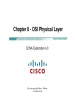
Activity 6.4.1: Basic VLSM Calculation and Addressing Design
Topology Diagram
Addressing Table
Device Interface IP Address Subnet Mask Default Gateway
Fa0/0
N/A
Fa0/1
N/A
S0/0/0
N/A
HQ
S0/0/1
N/A
Fa0/0
N/A
Fa0/1
N/A
S0/0/0
N/A
Branch1
S0/0/1
N/A
Fa0/0
N/A
Fa0/1
N/A
S0/0/0
N/A
Branch2
S0/0/1
N/A
All contents are Copyright © 1992–2007 Cisco Systems, Inc. All rights reserved. This document is Cisco Public Information. Page 1 of 5
This is trial version
www.adultpdf.com
CCNA Exploration
Routing Protocols and Concepts:
VLSM and CIDR Activity 6.4.1: Basic VLSM Calculation and Addressing Design
Learning Objectives
Upon completion of this activity, you will be able to:
• Determine the number of subnets needed.
• Determine the number of hosts needed for each subnet
• Design an appropriate addressing scheme using VLSM.
• Assign addresses and subnet mask pairs to device interfaces.
• Examine the use of the available network address space.
Scenario
In this activity, you have been given the network address 192.168.1.0/24 to subnet and provide the IP
addressing for the network shown in the Topology Diagram. VLSM will be used so that the addressing
requirements can be met using the 192.168.1.0/24 network. The network has the following addressing
requirements:
• The HQ LAN1 will require 50 host IP addresses.
• The HQ LAN2 will require 50 host IP addresses.
• The Branch1 LAN1 will require 20 host IP addresses.
• The Branch1 LAN2 will require 20 host IP addresses
• The Branch2 LAN1 will require 12 host IP addresses.
• The Branch2 LAN2 will require 12 host IP addresses.
• The link from HQ to Branch1 will require an IP address for each end of the link.
• The link from HQ to Branch2 will require an IP address for each end of the link.
• The link Branch1 to Branch2 will require an IP address for each end of the link.
(Note: Remember that the interfaces of network devices are also host IP addresses and are included
in the above addressing requirements.)
Task 1: Examine the Network Requirements.
Examine the network requirements and answer the questions below. Keep in mind that IP addresses will
be needed for each of the LAN interfaces.
1. How many subnets are needed?
_______
2. What is the maximum number of IP addresses that are needed for a single subnet? _______
3. How many IP addresses are needed for each of the BranchBranch1 LANs? _______
4. How many IP addresses are needed for each of the BranchBranch2 LANs?
_______
5. How many IP addresses are needed for each of the WAN links between routers?
_______
6. What is the total number of IP addresses that are needed? _______
7. What is the total number of IP addresses that are available in the 192.168.1.0/24 network?
_______
8. Can the network addressing requirements be met using the 192.168.1.0/24 network? _______
All contents are Copyright © 1992–2007 Cisco Systems, Inc. All rights reserved. This document is Cisco Public Information. Page 2 of 5
This is trial version
www.adultpdf.com
CCNA Exploration
Routing Protocols and Concepts:
VLSM and CIDR Activity 6.4.1: Basic VLSM Calculation and Addressing Design
Task 2: Design an IP Addressing Scheme
Step 1: Determine the subnet information for the largest network segment or segments.
In this case, the two HQ LANs are the largest subnets
.
1. How many IP addresses are needed for each LAN?
_______
2. What is the smallest size subnet that can be used to meet this requirement? _______
3. What is the maximum number of IP addresses that can be assigned in this size subnet? _______
Step 2: Assign subnets to HQ LANs.
Start at the beginning of the 192.168.1.0/24 network.
1. Assign the first available subnet to HQ LAN1.
2. Fill in the chart below with the appropriate information.
HQ LAN1 Subnet
Network
Address
Decimal
Subnet Mask
CIDR Subnet
Mask
First Usable IP
Address
Last Usable IP
Address
Broadcast
Address
3. Assign the next available subnet to HQ LAN2.
4. Fill in the chart below with the appropriate information.
HQ LAN2 Subnet
Network
Address
Decimal
Subnet Mask
CIDR Subnet
Mask
First Usable IP
Address
Last Usable IP
Address
Broadcast
Address
Step 3: Determine the subnet information for the next largest network segment or segments.
In this case, the two Branch1 LANs are the next largest subnets
.
1. How many IP addresses are needed for each LAN?
_______
2. What is the smallest size subnet that can be used to meet this requirement? _______
3. What is the maximum number of IP addresses that can be assigned in this size subnet? _______
30
Step 4: Assign subnet to BRANCH1 LANs.
Start with the IP address following the HQ LAN subnets.
1. Assign the next subnet to Branch1 LAN1.
2. Fill in the chart below with the appropriate information.
Branch1 LAN1 Subnet
Network
Address
Decimal
Subnet Mask
CIDR Subnet
Mask
First Usable IP
Address
Last Usable IP
Address
Broadcast
Address
3. Assign the next available subnet to Branch1 LAN2.
All contents are Copyright © 1992–2007 Cisco Systems, Inc. All rights reserved. This document is Cisco Public Information. Page 3 of 5
This is trial version
www.adultpdf.com
CCNA Exploration
Routing Protocols and Concepts:
VLSM and CIDR Activity 6.4.1: Basic VLSM Calculation and Addressing Design
4. Fill in the chart below with the appropriate information.
Branch1 LAN2 Subnet
Network
Address
Decimal
Subnet Mask
CIDR Subnet
Mask
First Usable IP
Address
Last Usable IP
Address
Broadcast
Address
Step 5: Determine the subnet information for the next largest network segment or segments.
In this case, the two Branch2 LANs are the next largest subnets.
1. How many IP addresses are needed for each LAN?
_______
2. What is the smallest size subnet that can be used to meet this requirement?
_______
3. What is the maximum number of IP addresses that can be assigned in this size subnet? _______
Step 6: Assign subnets to BRANCH2 LANs.
Start with the IP address following the Branch1 LAN subnets.
1. Assign the next subnet to the Branch2 LAN1. Fill in the chart below with the appropriate
information.
Branch2 LAN1 Subnet
Network
Address
Decimal
Subnet Mask
CIDR Subnet
Mask
First Usable IP
Address
Last Usable IP
Address
Broadcast
Address
2. Assign the next available subnet to Branch2 LAN2.
3. Fill in the chart below with the appropriate information.
Branch2 LAN2 Subnet
Network
Address
Decimal
Subnet Mask
CIDR Subnet
Mask
First Usable IP
Address
Last Usable IP
Address
Broadcast
Address
Step 7: Determine the subnet information for the links between the routers.
1. How many IP addresses are needed for each link?
_______
2. What is the smallest size subnet that can be used to meet this requirement? _______
3. What is the maximum number of IP addresses that can be assigned in this size subnet? _______
Step 8: Assign subnets to links.
Start with the IP address following the Branch2 LAN subnets.
1. Assign the next available subnet to the link between the HQ and Branch1 routers.
2. Fill in the chart below with the appropriate information.
Link between HQ and Branch1 Subnet
Network
Address
Decimal
Subnet Mask
CIDR Subnet
Mask
First Usable IP
Address
Last Usable IP
Address
Broadcast
Address
All contents are Copyright © 1992–2007 Cisco Systems, Inc. All rights reserved. This document is Cisco Public Information. Page 4 of 5
This is trial version
www.adultpdf.com
CCNA Exploration
Routing Protocols and Concepts:
VLSM and CIDR Activity 6.4.1: Basic VLSM Calculation and Addressing Design
3. Assign the next available subnet to the link between the HQ and Branch2 routers.
4. Fill in the chart below with the appropriate information.
Link between HQ and Branch2 Subnet
Network
Address
Decimal
Subnet Mask
CIDR Subnet
Mask
First Usable IP
Address
Last Usable IP
Address
Broadcast
Address
5. Assign the next available subnet to the link between the Branch1 and Branch2 routers.
6. Fill in the chart below with the appropriate information.
Link between Branch1 and Branch2 Subnet
Network
Address
Decimal
Subnet Mask
CIDR Subnet
Mask
First Usable IP
Address
Last Usable IP
Address
Broadcast
Address
Task 3: Assign IP Addresses to the Network Devices
Assign the appropriate addresses to the device interfaces. Document the addresses to be used in the
Addressing Table provided under the Topology Diagram.
Step 1: Assign addresses to the HQ router.
1. Assign the first valid host address in the HQ LAN 1 subnet to the Fa0/0 LAN interface.
2. Assign the first valid host address in the HQ LAN 2 subnet to the Fao/1 LAN interface.
3. Assign the first valid host address in the link between HQ and Branch1 subnet to the S0/0/0
interface.
4. Assign the first valid host address in the link between HQ and Branch2 subnet to the S0/0/1
interface.
Step 2: Assign addresses to the Branch1 router.
1. Assign the first valid host address in the Branch1 LAN1 subnet to the Fa0/0 LAN interface.
2. Assign the first valid host address in the Branch1 LAN2 subnet to the Fa0/1 LAN interface.
3. Assign the last valid host address on the link between Branch1 and HQ subnet to the S0/0/0
interface
4. Assign the first valid host address on the link between Branch1 and Branch2 subnet to the S0/0/1
interface.
Step 3: Assign addresses to the Branch2 router.
1. Assign the first valid host address in the Branch2 LAN1 subnet to the Fa0/0 LAN interface.
2. Assign the first valid host address in the Branch 2 LAN 2 subnet to the Fa0/1 LAN interface.
3. Assign the last valid host address on the link between HQ and Branch2 subnet to the S0/0/1
interface
4. Assign the last valid host address on the link between Branch1 and Branch2 subnet to the S0/0/0
interface.
All contents are Copyright © 1992–2007 Cisco Systems, Inc. All rights reserved. This document is Cisco Public Information. Page 5 of 5
This is trial version
www.adultpdf.com
All contents are Copyright © 1992–2007 Cisco Systems, Inc. All rights reserved. This document is Cisco Public Information. Page 1 of 11
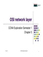
Activity 6.4.2: Challenge VLSM Calculation and Addressing Design
Topology Diagram
This is trial version
www.adultpdf.com
CCNA Exploration
Routing Protocols and Concepts:
VLSM and CIDR Activity 6.4.2: Challenge VLSM Calculation and Addressing Design
All contents are Copyright © 1992–2007 Cisco Systems, Inc. All rights reserved. This document is Cisco Public Information. Page 2 of 11
Learning Objectives
Upon completion of this activity, you will be able to:
Determine the number of subnets needed.
Determine the number of hosts needed for each subnet
Design an appropriate addressing scheme using VLSM.
Scenario
In this activity, you have been given the network address 172.16.0.0/16 to subnet and provide the IP
addressing for the network shown in the Topology Diagram. VLSM will be used so that the addressing
requirements can be met using the 172.16.0.0/16 network.
The network has the following addressing requirements:
East Network Section
The N-EAST (Northeast) LAN1 will require 4000 host IP addresses.
The N-EAST (Northeast) LAN2 will require 4000 host IP addresses.
The SE-BR1 (Southeast Branch1) LAN1 will require 1000 host IP addresses.
The SE-BR1 (Southeast Branch1) LAN2 will require 1000 host IP addresses.
The SE-BR2 (Southeast Branch2) LAN1 will require 500 host IP addresses.
The SE-BR2 (Southeast Branch2) LAN2 will require 500 host IP addresses.
The SE-ST1 (Southeast Satellite1) LAN1 will require 250 host IP addresses.
The SE-ST1 (Southeast Satellite1) LAN2 will require 250 host IP addresses.
The SE-ST2 (Southeast Satellite2) LAN1 will require 125 host IP addresses.
The SE-ST2 (Southeast Satellite2) LAN2 will require 125 host IP addresses.
West Network Section
The S-WEST (Southwest) LAN1 will require 4000 host IP addresses.
The S-WEST (Southwest) LAN2 will require 4000 host IP addresses.
The NW-BR1 (Northwest Branch1) LAN1 will require 2000 host IP addresses.
The NW-BR1 (Northwest Branch1) LAN2 will require 2000 host IP addresses.
The NW-BR2 (Northwest Branch2) LAN1 will require 1000 host IP addresses.
The NW-BR2 (Northwest Branch2) LAN2 will require 1000 host IP addresses.
Central Network Section
The Central LAN1 will require 8000 host IP addresses.
The Central LAN2 will require 4000 host IP addresses.
The WAN links between each of the routers will require an IP address for each end of the link.
(Note: Remember that the interfaces of network devices are also host IP addresses and are included
in the above addressing requirements.)
Task 1: Examine the Network Requirements.
Examine the network requirements and answer the questions below. Keep in mind that IP addresses will
be needed for each of the LAN interfaces.
1. How many LAN subnets are needed? _______
2. How many subnets are needed for the WAN links between routers? _______
This is trial version
www.adultpdf.com
CCNA Exploration
Routing Protocols and Concepts:
VLSM and CIDR Activity 6.4.2: Challenge VLSM Calculation and Addressing Design
All contents are Copyright © 1992–2007 Cisco Systems, Inc. All rights reserved. This document is Cisco Public Information. Page 3 of 11
3. How many total subnets are needed? _______
4. What is the maximum number of host IP addresses that are needed for a single subnet? _______
5. What is the least number of host IP addresses that are needed for a single subnet? _______
6. How many IP addresses are needed for the East portion of the network? Be sure to include the
WAN links between the routers. __________
7. How many IP addresses are needed for the West portion of the network? Be sure to include the
WAN links between the routers. __________
8. How many IP addresses are needed for the Central portion of the network? Be sure to include the
WAN links between the routers. __________
9. What is the total number of IP addresses that are needed? __________
10. What is the total number of IP addresses that are available in the 172.16.0.0/16 network?
_________
11. Can the network addressing requirements be met using the 172.16.0.0/16 network? _______
Task 2: Divide the Network into Three Subnetworks.
Step 1: Determine the subnet information for each network section.
To keep the subnets of each of the major network sections contiguous, begin by creating a main subnet
for each of the East, West, and Central network sections.
1. What is the smallest size subnet that can be used to meet the addressing requirement for the
East network? _______
2. What is the maximum number of IP addresses that can be assigned in this size subnet? _______
3. What is the smallest size subnet that can be used to meet the addressing requirement for the
West network? _______
4. What is the maximum number of IP addresses that can be assigned in this size subnet? _______
5. What is the smallest size subnet that can be used to meet the addressing requirement for the
Central network? _______
6. What is the maximum number of IP addresses that can be assigned in this size subnet? _______
Step 2: Assign subnets.
1. Start at the beginning of the 172.16.0.0/16 network. Assign the first available subnet to the East
section of the network.
2. Fill in the chart below with the appropriate information.
East Subnet
Network
Address
Decimal
Subnet Mask
CIDR Subnet
Mask
First Usable IP
Address
Last Usable IP
Address
Broadcast
Address
3. Assign the next available subnet to the West section of the network.
4. Fill in the chart below with the appropriate information.
This is trial version
www.adultpdf.com
CCNA Exploration
Routing Protocols and Concepts:
VLSM and CIDR Activity 6.4.2: Challenge VLSM Calculation and Addressing Design
All contents are Copyright © 1992–2007 Cisco Systems, Inc. All rights reserved. This document is Cisco Public Information. Page 4 of 11
West Subnet
Network
Address
Decimal
Subnet Mask
CIDR Subnet
Mask
First Usable IP
Address
Last Usable IP
Address
Broadcast
Address
5. Assign the next available subnet to the Central section of the network.
6. Fill in the chart below with the appropriate information.
Central Subnet
Network
Address
Decimal
Subnet Mask
CIDR Subnet
Mask
First Usable IP
Address
Last Usable IP
Address
Broadcast
Address
Task 3: Design an IP Addressing Scheme for the Central Network.
Step 1: Determine the subnet information for the Central LAN1.
Use the address space that was designated for the Central network in Task 1.
1. What is the smallest size subnet that can be used to meet this requirement? _______
2. What is the maximum number of IP addresses that can be assigned in this size subnet? _______
Step 2: Assign subnet to Central LAN1.
Start at the beginning of the address space designated for the Central network.
1. Assign the first subnet to the Central LAN1.
2. Fill in the chart below with the appropriate information.
Central LAN1 Subnet
Network
Address
Decimal Subnet
Mask
CIDR Subnet
Mask
First Usable IP
Address
Last Usable IP
Address
Broadcast
Address
Step 3: Determine the subnet information for the Central LAN2.
1. What is the smallest size subnet that can be used to meet this requirement? _______
2. What is the maximum number of IP addresses that can be assigned in this size subnet? _______
Step 4: Assign subnet to Central LAN2.
1. Assign the next available subnet to the Central LAN2.
2. Fill in the chart below with the appropriate information.
Central LAN2 Subnet
Network
Address
Decimal Subnet
Mask
CIDR Subnet
Mask
First Usable IP
Address
Last Usable IP
Address
Broadcast
Address
This is trial version
www.adultpdf.com
CCNA Exploration
Routing Protocols and Concepts:
VLSM and CIDR Activity 6.4.2: Challenge VLSM Calculation and Addressing Design
All contents are Copyright © 1992–2007 Cisco Systems, Inc. All rights reserved. This document is Cisco Public Information. Page 5 of 11
Step 5: Determine the subnet information for the WAN link between the Central router and the HQ
router.
1. What is the smallest size subnet that can be used to meet this requirement? _______
2. What is the maximum number of IP addresses that can be assigned in this size subnet? _______
Step 6: Assign subnet to WAN link.
1. Assign the next available subnet to the WAN link between the Central router and the HQ router.
2. Fill in the chart below with the appropriate information.
WAN link between Central and HQ Subnet
Network
Address
Decimal Subnet
Mask
CIDR Subnet
Mask
First Usable IP
Address
Last Usable IP
Address
Broadcast
Address
Task 4: Design an IP Addressing Scheme for the West Network.
Step 1: Determine the subnet information for the S-WEST LAN1.
Use the address space that was designated for the West network in Task 1.
1. What is the smallest size subnet that can be used to meet this requirement? _______
2. What is the maximum number of IP addresses that can be assigned in this size subnet? _______
Step 2: Assign subnet to S-WEST LAN1.
Start at the beginning of the address space designated for the West network.
1. Assign the first subnet to the S-WEST LAN1.
2. Fill in the chart below with the appropriate information.
S-WEST LAN1 Subnet
Network
Address
Decimal Subnet
Mask
CIDR Subnet
Mask
First Usable IP
Address
Last Usable IP
Address
Broadcast
Address
Step 3: Determine the subnet information for the S-WEST LAN2.
1. What is the smallest size subnet that can be used to meet this requirement? _______
2. What is the maximum number of IP addresses that can be assigned in this size subnet? _______
Step 4: Assign subnet to S-WEST LAN2.
1. Assign the next available subnet to the S-WEST LAN2.
2. Fill in the chart below with the appropriate information.
S-WEST LAN2 Subnet
Network
Address
Decimal Subnet
Mask
CIDR Subnet
Mask
First Usable IP
Address
Last Usable IP
Address
Broadcast
Address
This is trial version
www.adultpdf.com
CCNA Exploration
Routing Protocols and Concepts:
VLSM and CIDR Activity 6.4.2: Challenge VLSM Calculation and Addressing Design
All contents are Copyright © 1992–2007 Cisco Systems, Inc. All rights reserved. This document is Cisco Public Information. Page 6 of 11
Step 5: Determine the subnet information for the NW-BR1 LAN1.
1. What is the smallest size subnet that can be used to meet this requirement? _______
2. What is the maximum number of IP addresses that can be assigned in this size subnet? _______
Step 6: Assign subnet to NW-BR1 LAN1.
1. Assign the next available subnet to the NW-BR1 LAN1.
2. Fill in the chart below with the appropriate information.
NW-BR1 LAN1 Subnet
Network
Address
Decimal Subnet
Mask
CIDR Subnet
Mask
First Usable IP
Address
Last Usable IP
Address
Broadcast
Address
Step 7: Determine the subnet information for the NW-BR1 LAN2.
1. What is the smallest size subnet that can be used to meet this requirement? _______
2. What is the maximum number of IP addresses that can be assigned in this size subnet? _______
Step 8: Assign subnet to NW-BR1 LAN2.
1. Assign the next available subnet to the NW-BR1 LAN2.
2. Fill in the chart below with the appropriate information.
NW-BR1 LAN2 Subnet
Network
Address
Decimal Subnet
Mask
CIDR Subnet
Mask
First Usable IP
Address
Last Usable IP
Address
Broadcast
Address
Step 9: Determine the subnet information for the NW-BR2 LAN1.
1. What is the smallest size subnet that can be used to meet this requirement? _______
2. What is the maximum number of IP addresses that can be assigned in this size subnet? _______
Step 10: Assign subnet to NW-BR2 LAN1.
1. Assign the next available subnet to the NW-BR2 LAN1.
2. Fill in the chart below with the appropriate information.
NW-BR2 LAN1 Subnet
Network
Address
Decimal Subnet
Mask
CIDR Subnet
Mask
First Usable IP
Address
Last Usable IP
Address
Broadcast
Address
Step 11: Determine the subnet information for the NW-BR2 LAN2.
1. What is the smallest size subnet that can be used to meet this requirement? _______
2. What is the maximum number of IP addresses that can be assigned in this size subnet? _______
This is trial version
www.adultpdf.com
CCNA Exploration
Routing Protocols and Concepts:
VLSM and CIDR Activity 6.4.2: Challenge VLSM Calculation and Addressing Design
All contents are Copyright © 1992–2007 Cisco Systems, Inc. All rights reserved. This document is Cisco Public Information. Page 7 of 11
Step 12: Assign subnet to NW-BR2 LAN2.
1. Assign the next available subnet to the NW-BR2 LAN2.
2. Fill in the chart below with the appropriate information.
NW-BR2 LAN2 Subnet
Network
Address
Decimal Subnet
Mask
CIDR Subnet
Mask
First Usable IP
Address
Last Usable IP
Address
Broadcast
Address
Step 13: Determine the subnet information for the WAN links between the routers in the West
network.
1. How many router to router WAN links are present in the West network? _______
2. How many IP addresses are needed for each of these WAN links? _______
3. What is the smallest size subnet that can be used to meet this requirement? _______
4. What is the maximum number of IP addresses that can be assigned in this size subnet? _______
Step 14: Assign subnets to WAN links.
1. Assign the next available subnets to the WAN links between the routers.
2. Fill in the chart below with the appropriate information.
WAN links between the Routers in the West Network
WAN
Link
Network
Address
Decimal Subnet
Mask
CIDR
Subnet
Mask
First Usable IP
Address
Last Usable IP
Address
Broadcast
Address
HQ to
WEST
WEST to
S-WEST
WEST to
N-WEST
N-WEST to
NW-BR1
N-WEST to
NW-BR2
Task 5: Design an IP Addressing Scheme for the East Network.
Step 1: Determine the subnet information for the N-EAST LAN1.
Use the address space that was designated for the East network in Task 1.
1. What is the smallest size subnet that can be used to meet this requirement? _______
2. What is the maximum number of IP addresses that can be assigned in this size subnet? _______
Step 2: Assign subnet to N-EAST LAN1.
Start at the beginning of the address space designated for the East network.
1. Assign the first subnet to the N-EAST LAN1.
This is trial version
www.adultpdf.com
CCNA Exploration
Routing Protocols and Concepts:
VLSM and CIDR Activity 6.4.2: Challenge VLSM Calculation and Addressing Design
All contents are Copyright © 1992–2007 Cisco Systems, Inc. All rights reserved. This document is Cisco Public Information. Page 8 of 11
2. Fill in the chart below with the appropriate information.
N-EAST LAN1 Subnet
Network
Address
Decimal Subnet
Mask
CIDR Subnet
Mask
First Usable IP
Address
Last Usable IP
Address
Broadcast
Address
Step 3: Determine the subnet information for the N-EAST LAN2.
1. What is the smallest size subnet that can be used to meet this requirement? _______
2. What is the maximum number of IP addresses that can be assigned in this size subnet? _______
Step 4: Assign subnet to N-EAST LAN2.
1. Assign the next available subnet to the N-EAST LAN2.
2. Fill in the chart below with the appropriate information.
N-EAST LAN2 Subnet
Network
Address
Decimal Subnet
Mask
CIDR Subnet
Mask
First Usable IP
Address
Last Usable IP
Address
Broadcast
Address
Step 5: Determine the subnet information for the SE-BR1 LAN1.
1. What is the smallest size subnet that can be used to meet this requirement? _______
2. What is the maximum number of IP addresses that can be assigned in this size subnet? _______
Step 6: Assign subnet to SE-BR1 LAN1.
1. Assign the next available subnet to the SE-BR1 LAN1.
2. Fill in the chart below with the appropriate information.
SE-BR1 LAN1 Subnet
Network
Address
Decimal Subnet
Mask
CIDR Subnet
Mask
First Usable IP
Address
Last Usable IP
Address
Broadcast
Address
Step 7: Determine the subnet information for the SE-BR1 LAN2.
1. What is the smallest size subnet that can be used to meet this requirement? _______
2. What is the maximum number of IP addresses that can be assigned in this size subnet? _______
Step 8: Assign subnet to SE-BR1 LAN2.
1. Assign the next available subnet to the SE-BR1 LAN2.
This is trial version
www.adultpdf.com
CCNA Exploration
Routing Protocols and Concepts:
VLSM and CIDR Activity 6.4.2: Challenge VLSM Calculation and Addressing Design
All contents are Copyright © 1992–2007 Cisco Systems, Inc. All rights reserved. This document is Cisco Public Information. Page 9 of 11
2. Fill in the chart below with the appropriate information.
SE-BR1 LAN2 Subnet
Network
Address
Decimal Subnet
Mask
CIDR Subnet
Mask
First Usable IP
Address
Last Usable IP
Address
Broadcast
Address
Step 9: Determine the subnet information for the SE-BR2 LAN1.
1. What is the smallest size subnet that can be used to meet this requirement? _______
2. What is the maximum number of IP addresses that can be assigned in this size subnet? _______
Step 10: Assign subnet to SE-BR2 LAN1.
1. Assign the next available subnet to the SE-BR2 LAN1.
2. Fill in the chart below with the appropriate information.
SE-BR2 LAN1 Subnet
Network
Address
Decimal Subnet
Mask
CIDR Subnet
Mask
First Usable IP
Address
Last Usable IP
Address
Broadcast
Address
Step 11: Determine the subnet information for the SE-BR2 LAN2.
1. What is the smallest size subnet that can be used to meet this requirement? _______
2. What is the maximum number of IP addresses that can be assigned in this size subnet? _______
Step 12: Assign subnet to SE-BR2 LAN2.
1. Assign the next available subnet to the SE-BR2 LAN2.
2. Fill in the chart below with the appropriate information.
SE-BR2 LAN2 Subnet
Network
Address
Decimal Subnet
Mask
CIDR Subnet
Mask
First Usable IP
Address
Last Usable IP
Address
Broadcast
Address
Step 13: Determine the subnet information for the SE-ST1 LAN1.
1. What is the smallest size subnet that can be used to meet this requirement? _______
2. What is the maximum number of IP addresses that can be assigned in this size subnet? _______
Step 14: Assign subnet to SE-ST1 LAN1.
1. Assign the next available subnet to the SE-ST1 LAN1.
This is trial version
www.adultpdf.com
CCNA Exploration
Routing Protocols and Concepts:
VLSM and CIDR Activity 6.4.2: Challenge VLSM Calculation and Addressing Design
All contents are Copyright © 1992–2007 Cisco Systems, Inc. All rights reserved. This document is Cisco Public Information. Page 10 of 11
2. Fill in the chart below with the appropriate information.
SE-ST1 LAN1 Subnet
Network
Address
Decimal Subnet
Mask
CIDR Subnet
Mask
First Usable IP
Address
Last Usable IP
Address
Broadcast
Address
Step 15: Determine the subnet information for the SE-ST1 LAN2.
1. What is the smallest size subnet that can be used to meet this requirement? _______
2. What is the maximum number of IP addresses that can be assigned in this size subnet? _______
Step 16: Assign subnet to SE-ST1 LAN2.
1. Assign the next available subnet to the SE-ST1 LAN2.
2. Fill in the chart below with the appropriate information.
SE-ST1 LAN2 Subnet
Network
Address
Decimal Subnet
Mask
CIDR Subnet
Mask
First Usable IP
Address
Last Usable IP
Address
Broadcast
Address
Step 17: Determine the subnet information for the SE-ST2 LAN1.
1. What is the smallest size subnet that can be used to meet this requirement? _______
2. What is the maximum number of IP addresses that can be assigned in this size subnet? _______
Step 18: Assign subnet to SE-ST2 LAN1.
1. Assign the next available subnet to the SE-ST2 LAN1.
2. Fill in the chart below with the appropriate information.
SE-ST2 LAN1 Subnet
Network
Address
Decimal Subnet
Mask
CIDR Subnet
Mask
First Usable IP
Address
Last Usable IP
Address
Broadcast
Address
Step 19: Determine the subnet information for the SE-ST2 LAN2.
1. What is the smallest size subnet that can be used to meet this requirement? _______
2. What is the maximum number of IP addresses that can be assigned in this size subnet? _______
Step 20: Assign subnet to SE-ST2 LAN2.
1. Assign the next available subnet to the SE-ST2 LAN2.
This is trial version
www.adultpdf.com