Root Cause Failure Analysis Part 8 pot
Bạn đang xem bản rút gọn của tài liệu. Xem và tải ngay bản đầy đủ của tài liệu tại đây (1.26 MB, 30 trang )
CONTROL
VALVES
Control valves can be broken into two major classifications: process and fluid power.
Process valves control the flow
of
gases and liquids through a process system. Fluid-
power valves control pneumatic or hydraulic systems.
PROCESS
Process-control valves are available in a variety
of
sizes, configurations, and materials
of
construction. Generally, this type
of
valve is classified by its internal configuration.
Configuration
The device used to control flow through a valve varies with its intended function. The
more common types are ball, gate, butterfly, and globe valves.
Ball
Ball valves (see Figure
17-1)
are simple shutoff devices that use a ball to stop and
start the flow
of
fluid downstream
of
the valve.
As
the valve stem turns to the open
position, the ball rotates to a point where part or all
of
the hole machined through the
ball is in line with the valve-body inlet and outlet. This allows fluid to pass through
the valve. When the ball rotates
so
that the hole is perpendicular to the flow path, the
flow stops.
Most ball valves are quick-acting and require a
90"
turn
of
the actuator lever to fully
open or close the valve.
This
feature, coupled with the turbulent flow generated when
the ball opening is only partially open, limits the use
of
the ball valve. Use should be
limited to strictly an ordoff control function (Le., fully open or fully closed) because
of the turbulent flow condition and severe friction loss when in the partially open
position. These valves should not be used for throttling or flow control.
202
Control
Valves
203
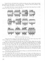
Figure
17-1
Ball valve.
Ball valves used in process applications may incorporate a variety of actuators to pro-
vide direct
or
remote control
of
the valve. Actuators commonly are either manual or
motor operated. Manual values have a handwheel or lever attached directly or through
a gearbox to the valve stem. The valve is opened or closed by moving the valve stem
through a
90"
arc. Motor-controlled valves replace the handwheel with a fractional
horsepower motor that can be controlled remotely. The motor-operated valve operates
in exactly the same way as
the
manually operated valve.
Gate
Gate valves are used when straight-line, laminar fluid flow and minimum restrictions
are
needed. These valves use a wedge-shaped sliding plate in the valve body to stop,
throttle, or permit full flow of fluids through the valve. When the valve is wide open,
the gate is completely inside the valve bonnet. This leaves the flow passage through
the valve fully open, with no flow restrictions, allowing little or
no
pressure drop
through the valve.
Gate valves are not suitable for throttling
the
flow volume unless specifically autho-
rized for this application by the manufacturer. They generally are not suitable because
the flow of fluid through a partially open gate can cause extensive damage to the
valve.
Gate valves are classified as either rising stem or non-rising stem. In the non-rising-
stem valve, shown in Figure
17-2,
the stem is threaded into the gate. As the hand-
wheel on the stem is rotated, the gate travels up or down the stem on the threads,
while the stem remains vertically stationary. This type of valve almost always will
have a pointer indicator threaded onto the upper end
of
the stem to indicate the posi-
tion of the gate.
204
Root
Cause Failure Analysis
Figure
17-2
Non-rising-stem gate valve (source unknown).
Valves with rising stems (see Figure
17-3)
are used when it is important to know by
immediate inspection
if
the valve is open or closed
or
when the threads exposed to the
fluid could become damaged by fluid contamination. In this valve, the stem rises out
of
the valve bonnet when the valve
is
opened.
Butte
fly
The butterfly valve has a disk-shaped element that rotates about a central shaft or
stem. When the valve is closed, the disk face
is
across the pipe and blocks the flow.
Depending on the type
of
butterfly valve, the seat may consist of a bonded resilient
Figure
17-3
Rising stem gate valve.
Control
Valves
205
liner, a mechanically fastened resilient liner, an insert-type reinforced resilient liner,
or an integral metal seat with an O-ring inserted around the edge of the disk.
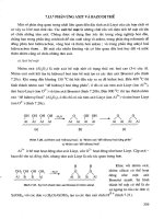
As shown in Figure 174, both the fully open and the throttled positions permit
almost unrestricted flow. Therefore, this valve does not induce turbulent flow in
the
partially closed position. While the design does not permit exact flow control, a but-
terfly valve can be used for throttling flow through the valve. In addition, these valves
have the lowest pressure drop of all the conventional types. For such reasons, they
commonly are used in process-control applications.
Globe
The globe valve gets its name from the shape of the valve body, although other types
of valves also may have globular bodies. Figure 17-5 shows three configurations of
this
type
of valve: straight flow, angle flow and cross flow.
A disk attached to the valve stem controls flow in
a
globe valve. Turning the valve
stem until the disk is seated, illustrated in View
A of Figure 17-6, closes the valve.
The edge
of
the disk and the seat are very accurately machined to form a tight seal. It
is
important for globe valves to be installed with the pressure against the disk face to
protect the stem packing from system pressure when the valve is shut.
While
this type of valve commonly is used in the fully open or fully closed position, it
also may be used for throttling. However, since the seating surface is a relatively large
area, it is not suitable for throttling applications where fine adjustments are required.
When the valve is open, as illustrated in View
B
of Figure 17-6, the fluid flows through
the space between the edge of the disk and the seat. Since the fluid flow is equal on all
sides of
the
center of support when the valve is open, no unbalanced pressure is placed
Figure
17-4
Buttefly valves provide almost unreshictedjlow (Higgins and Mobley
1995).
206
Root
Cause
Failure
Analysis
Straight
-
flow
Angle
-
flow
Cross
-
flow
Figure 17-5 Three globe valve configurations: straightjlow, angle flow,
and
cross
&w.
on the disk to cause uneven wear. The rate at which fluid flows through the valve is reg-
ulated by the position of the disk in relation to the valve seat.
The globe valve should never be jammed in the open position. After a valve is fully
opened, the handwheel
or
actuating handle should be closed approximately one-half
turn.
If
this is not done, the valve may seize in the open position making it difficult, if
not impossible, to close the valve. Many valves are damaged in the manner. Another
reason to partially close a globe valve
is
because
it
can be difficult to tell if the valve is
open or closed.
If
jammed in the open position, the stem can be damaged or broken by
someone who thinks the valve
is
closed.
Performance
Process-control valves have few measurable criteria that can be used to determine
their performance. Obviously, the valve must provide
a
positive seal when closed.
View
A
View
B
Figure 17-6 Globe valve.
Control
Valves
207
In addition, it must provide a relatively laminar flow with minimum pressure drop
in the fully open position. When evaluating valves, the following criteria should be
considered: capacity rating, flow characteristics, pressure drop, and response char-
acteristics.
Capacity Rating
The primary selection criteria of a control valve is its capacity rating. Each type of
valve is available in a variety of sizes to handle most typical process-flow rates. How-
ever, proper size selection is critical to the performance characteristics of the valve
and the system where it is installed. A valve’s capacity must accommodate variations
in
viscosity, temperature, flow rates, and upstream pressure.
Flow
Characteristics
The internal design of process-control valves has a direct impact on the flow charac-
teristics of the gas or liquid flowing through the valve. A fully open butterfly
or
gate
valve provides a relatively straight, obstruction-free flow path. As a result, the product
should not be affected. Refer to the previous section
on
valve configuration for a dis-
cussion of the flow characteristics by
valve
type.
Pressure Drop
The control-valve configuration affects the resistance to flow through the valve. The
amount
of
resistance,
or
pressure drop, will vary greatly, depending
on
type, size, and
position of the valve’s flow-control device (i.e., ball, gate,
or
disk). Pressure-drop for-
mulas can be obtained for all common valve types from several sources.
Response Characteristics
With the exception
of
simple, manually controlled shutoff valves, process-control
valves generally are used to control the volume and pressure of gases or liquids within
a process system.
In
most applications, valves are controlled from a remote location
through the use of pneumatic, hydraulic,
or
electronic actuators. Actuators are used to
position the gate, ball, or disk that starts, stops, directs,
or
proportions the flow of gas
or liquid through the valve. Therefore, the response characteristics of a valve are
determined, in
part,
by the actuator. Three factors critical
to
proper valve operation are
response time, length of travel, and repeatability.
Response Time
Response time is the total time required for a valve to open
or
close
to a specific set-point position. These positions are fully open, fully closed, and any
position in between. The selection and maintenance of the actuator used to control
process-control valves have a major impact
on
response time.
Length ofTravel
The valve’s flow-control device (Le., gate, ball,
or
disk) must
travel some distance when going from one set point to another. With a manually oper-
ated valve, this is a relatively simple operation.
The
operator moves the stem lever
or
handwheel until the desired position is reached. The only reasons why a manually
208
Root
Cause
Failure
Analysis
controlled valve will not position properly are mechanical wear or looseness between
the lever or handwheel and the disk, ball, or gate.
For remotely controlled valves, however, other variables have a direct impact on valve
travel. These variables depend on the type
of
actuator used. There
are
three major
types
of
actuators: pneumatic, hydraulic, and electronic.
Pneumatic actuators, including diaphragms, air motors, and cylinders, are suitable for
simple
odoff
valve applications.
As
long as there is enough air volume and pressure
to activate the actuator, the valve can be repositioned over its full length of travel.
However, when the air supply required to power the actuator
is
inadequate or the pro-
cess-system pressure is too great, the actuator’s ability to operate
the
valve properly is
severely reduced.
A
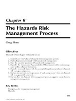
pneumatic (Le., compressed-air driven) actuator is shown in Figure 17-7. This type
is not suited for precision flow-control applications, because the compressibility of air
prevents it from providing smooth, accurate valve positioning.
Hydraulic (Le., fluid-driven) actuators, also illustrated in Figure 17-7, can provide a
positive means
of
controlling process valves in most applications. Properly installed
and maintained,
this
type of actuator can provide accurate, repeatable positioning of
the control valve over its full range
of
travel.
Some control valves use high-torque electric motors as their actuator (see
Figure
17-8).
If
the motors
are
properly sized and their control circuits maintained,
this
type
of
actuator can provide reliable, positive control over the full range
of
travel.
Figure
17-7
Pneumatic or hydraulic cylinders are used
as
actuators (Higgins
and
Mobley
1995).
Control
Valves
209
Motor
Actuator
Figure
1995).
17-8 High-torque electric motors can be used as actuators (Higgins and Mobley
Repeatability
Repeatability, perhaps, is the most important performance criteria
of
a process-control valve. This is especially true in applications where precise
flow
or
pressure control is needed for optimum performance of the process system.
New process-control valves generally provide the repeatability required. However,
proper maintenance and periodic calibration
of
the valves and their actuators are
required to ensure long-term performance. This is especially true for valves that use
mechanical linkages as part of the actuator assembly.
Installation
Process-control valves cannot tolerate solids, especially abrasives, in the gas or liq-
uid stream. In applications where high concentrations of particulates are present,
valves tend to experience chronic leakage or seal problems because the particulate
matter prevents the ball, disk, or gate from completely closing against the stationary
surface.
210
Root
Cause Failure
Analysis
Simply installing a valve with the same inlet and discharge size as the piping used in
the process is not acceptable. In most cases, the valve must be larger than the piping to
compensate for flow restrictions within the valve.
Operafing Methods
Operating methods for control valves, which are designed to control
or
direct gas and
liquid flow through process systems or fluid-power circuits, range from manual to
remote, automatic operation. The key parameters that govern the operation of valves
are the speed of the control movement and the impact of speed on the system. This is
especially important in process systems.
Hydraulic hammer, the shock wave generated by the rapid change in the flow rate of
liquids within a pipe
or
vessel, has a serious, negative impact on all components of the
process system.
For
example, instantaneously closing a large flow-control valve may
generate in excess of
3
million foot-pounds
of
force on the entire system upstream
of
the valve. This shock wave can cause catastrophic failure of upstream valves, pumps,
welds, and other system components.
Changes in flow rate, pressure, direction, and other controllable variables must be
gradual enough to permit a smooth transition. Abrupt changes in valve position should
be avoided. Neither the valve installation nor the control mechanism should permit
complete shutoff, referred to as
deadheading,
of any circuit in a process system.
Restricted flow forces system components, such
as
pumps, to operate outside of their
performance envelope.
This
reduces equipment reliability and sets the stage for cata-
strophic failure
or
abnormal system performance. In applications where radical changes
in flow are required for normal system operation, control valves should
be
configured to
provide an adequate bypass for surplus flow in order to protect the system.
For
example, systems that must have close control
of
flow should use two proportion-
ing valves that act in tandem to maintain a balanced hydraulic or aerodynamic system.
The primary,
or
master, valve should control flow to the downstream process. The sec-
ond valve, slaved to the master, should divert excess flow to a bypass loop. This mas-
ter-slave approach ensures that the pumps and other upstream system components are
permitted
to
operate well within their operating envelope.
FLUID
POWER
Fluid power control valves are used on pneumatic and hydraulic systems or circuits.
Configuration
The configuration of fluid power control valves varies with their intended application.
The more common configurations include one way, two way, three way, and four way.
Control
Valves
21
1
One
Way
One-way valves typically are used for flow and pressure control in fluid-power cir-
cuits (see Figure
17-9).
Flow-control valves regulate the flow of hydraulic fluid or
gases
in
these systems. Pressure-control valves, in the form of regulators or relief
valves, control the amount of pressure transmitted downstream from the valve.
In
most cases, the types of valves used for flow control are smaller versions of the types
of valves used in process control. The major types of process-control valves were dis-
cussed previously. These include ball, gate, globe, and butterfly valves.
Pressure-control valves have a third port to vent excess pressure and prevent
it
from
affecting the downstream piping. The bypass, or exhaust, port has an internal flow-
control device, such as a diaphragm or piston, that opens at predetermined set points
to permit the excess pressure to bypass the valve’s primary discharge.
In
pneumatic
circuits, the bypass port vents to the atmosphere.
In
hydraulic circuits, it must be con-
nected to a piping system that returns to the hydraulic reservoir.
Two
Way
A
two-way valve has two functional flow-control
ports.
A
two-way, sliding spool
directional control valve is shown in Figure 17-10.
As
the spool moves back and
forth, it either allows fluid to flow through the valve or prevents it from flowing. In the
open position, the fluid enters the inlet port, flows around the shaft of the spool, and
through the outlet port. Because the forces in the cylinder are equal when open, the
spool cannot move back and forth.
In
the closed position, one
of
the spool’s pistons
simply blocks the inlet port, which prevents flow through the valve.
/SPRING
NO
FLOW
BODY
/
IN
OUT
FREE
FLOW
Figure
17-9
One-way,
fluidpower valve.
212
Root
Cause
Failure
Analysis
IN
$.
IN
$.
CLOSED
$.
WT
Figure 17-10 Two-way, fluid-power valve (Nelson 1986).
A
number
of
features common to most sliding-spool valves are shown in
Figure
17-10.
The small ports at either end
of
the valve housing provide
a
path for
fluid that leaks past the spool to
flow
to the reservoir. This prevents pressure from
building up against the ends
of
the pistons, which would hinder the movement of the
spool. When these valves become
worn,
they may lose balance because
of
greater
leakage on one side
of
the spool than on the other. This can cause the spool to stick as
it attempts to move back and
forth.
Therefore, small grooves are machined around the
sliding surface of the piston. In hydraulic valves, leaking liquid encircles the piston,
keeping the contacting surfaces lubricated and centered.
Three
Way
Three-way valves contain a pressure port, cylinder port, and return or exhaust port
(see Figure
17-1
1).
The three-way directional control valve is designed to operate an
I1
12
B
Y3
il
Figure 17-11 Three-way, fluid-power valve (Nelson 1986).
Control
Valves
213
actuating unit in one direction. It
is
returned to its original position either by a spring
or the load on the actuating unit.
Four
Way
Most actuating devices require system pressure in order to operate in two directions.
The four-way directional control valve, which contains four ports, is used to control
the operation of such devices (see Figure
17-12).
The four-way valve also is used in
some systems to control the operation of other valves. It is one of the most widely
used directional-control valves in fluid-power systems.
The
typical
four-way directional control valve has four ports: a pressure
port,
a return
port, and two cylinder or work (output) ports. The pressure port is connected to the
main system-pressure line and
the
return port is connected to the reservoir return line.
The two outputs are connected to
the
actuating unit.
Performance
The criteria that determines performance of fluid-power valves are similar to those for
process-control valves
as
discussed previously.
As
with process-control valves, fluid-
power valves must be selected based on their intended application and function.
Installation
When installing fluid power control valves, piping connections are made either
directly to the valve body
or
to a manifold attached to the valve’s base. Care should be
taken to ensure that the piping is connected to the proper valve port. The schematic
diagram affixed to the valve body will indicate the proper piping arrangement, as well
AIR
INTRODUCED THROUGH CENTERING SPRINGS PUSH AGAINST
THIS PASSAGE PUSHES
AGAINST THE PISTON
WHICH SHIFTS
THE
SPOOL
TO
THE
RIGHT
\
WASHERS CENTERING WASHERS TO
n
CENTER THE
SPOOL
WHEN
\
NO
AIR
IS
APPLIED
PISTONS
SEAL
THE
AIR
CHAMBER FROM
THE HYDRAULIC CHAMBER
\
Figure
17-12
Four-way,jiuid-power
valves.
214
Root
Cause
Failure
Analysis
as the designed operation of the valve. In addition, the ports on most fluid-power
valves generally are clearly marked to indicate their intended function.
In hydraulic circuits, the return
or
common ports should be connected to a return line
that directly connects the valve to the reservoir tank. This return line should not need
a pressure-control device but should have a check valve to prevent reverse flow of the
hydraulic fluid.
Pneumatic circuits may be vented directly to atmosphere.
A
return line can be used to
reduce noise or any adverse effect that locally vented compressed air might have on
the area.
Operating
Methods
The function and proper operation of a fluid-power valve are relatively simple. Most
of these valves have a schematic diagram affixed to the body that clearly explains how
to operate the valve.
Backup
Valves
Figure 17-13 is a schematic of a two-position, cam-operated valve. The primary actu-
ator,
or
cam, is positioned on the left of the schematic and any secondary actuators are
on the right. In this example, the secondary actuator consists of a spring-return and a
spring-compensated limit switch. The schematic indicates that, when the valve is in
the neutral position (right box), flow is directed from
the
inlet
(Pj
to work port
A.
When the cam is depressed, the flow momentarily shifts to work port
B.
The second-
ary
actuator, or spring, automatically returns the valve to its neutral position when the
cam returns to its extended position. In these schematics, T indicates the return con-
nection to the reservoir.
Figure 17-14 illustrates a typical schematic
of
a two-position and three-position
directional control valve. The boxes contain flow direction arrows that indicate the
flow path in each position. The schematics do not include the actuators used to acti-
vate
or
shift the valves between positions.
In a two-position valve, the flow path is always directed to one of the work ports
(A
or
B).
In
a
three-position valve, a third
or
neutral position is added. In this figure, a Type
2
center position is used. In the neutral position,
all
ports are blocked and no flow
through the valve is possible.
Figure 17-15 is the schematic for the center
or
neutral position
of
three-position
directional control valves. Special attention should
be
given to the type of center posi-
tion that is used in a hydraulic control valve. When Type
2,
3, and
6
(see
Figure
17-15)
are
used,
the
upstream side of the valve must have
a
relief or bypass
valve installed. Since the pressure port is blocked, the valve cannot relieve pressure on
the upstream side
of
the valve. The Type
4
center position, called a
motor
spool,
per-
Control
Valves
A
PUSH
ROD
TRIPS
SWITCH
WHEN
SPWNG
HOLDS
VALVE
OFFSET
IN
NORMAL
OPERATION
j-w
Figure
17-13
Schematic for a cam-operated, two-position valve.
~
P
T
P
T
2-Position
Valve
w
P
T
P
T
P
1
215
3-Position
Valve
Figure
17-14
Schematic
of
two-position and three-position valves.
216
Root
Cause
Failure
Analysis
PT PT
U'JI
PT
El
PT
PT
PT
Type
3
Type
4
Type
6
Figure
17-15
Schematic
for
center
or
neutral configurations
of
three-position valves.
mits the full pressure and volume on the upstream side of
the
valve to flow directly to
the return line and storage reservoir.
This
is the recommended center position for most
hydraulic circuits.
The schematic affixed to the valve includes
the
primary and secondary actuators used
to control the valve. Figure 17-16 provides the schematics for three actuator-con-
trolled valves:
1.
Double-solenoid, spring-centered, three-position valve;
2.
Solenoid-operated, spring-return, two-position valve;
3.
Double-solenoid, detented, two-position valve.
The top schematic represents a double-solenoid, spring-centered, three-position
valve. When neither of the two solenoids is energized, the double springs ensure that
the valve is in its center or neutral position. In this example, a Type
0
(see
Figure 17-1
5)
configuration is used. This neutral-position configuration equalizes the
pressure through the valve. Since the pressure port is open to
both
work ports and the
return line, pressure is equalized throughout the system. When the left
or
primary
solenoid is energized, the valve shifts to the left-hand position and directs pressure to
work port
B.
In this position, fluid in the
A
side
of
the circuit returns to the reservoir.
As
soon as the solenoid is de-energized, the valve shifts back to the neutral
or
center
position. When the secondary (Le., right) solenoid is energized, the valve redirects
flow to port
A
and port
B
returns fluid to the reservoir.
The middle schematic represents a solenoid-operated, spring-return, two-position
valve. Unless the solenoid is energized, the pressure port
(P)
is connected to work port
A.
While the solenoid is energized, flow is redirected to work port
B.
The spring
Control
Valves
217
Figure 17-1
6
Actuator-controlled valve schematics.
return ensures that the valve is in its neutral (i.e., right) position when the solenoid is
de-energized.
The bottom schematic represents a double-solenoid, detented, two-position valve.
The solenoids are used to shift the valve between its two positions.
A
secondary
device, called a
detent,
is used to hold the valve in its last position until the alternate
solenoid
is
energized. Detent configuration varies with the valve type and manufac-
turer. However, all configurations prevent the valve’s control device from moving
until a strong force, such as that provided by the solenoid, overcomes its locking
force.
Actuators
As
with process-control valves, actuators used to control fluid-power valves have a
fundamental influence
on
performance. The actuators must provide positive, real-time
response to control inputs. The primary types
of
actuators used to control fluid-power
valves are mechanical, pilot, and solenoid.
Mechanical
The use
of
manually controlled mechanical valves is limited
in
both
pneumatic and hydraulic circuits. Generally, this type of actuator
is
used
only
on
isolation valves that are activated when the circuit
or
fluid-power system
is
shut
down for repair or when direct operator input is required to operate one of the
sys-
tem components.
218
Root
Cause Failure
Analysis
Manual control devices (e.g., levers, cams,
or
palm buttons) can be used as the pri-
mary actuator on most fluid power control valves. Normally, these actuators are used
in conjunction with a secondary actuator, such as a spring return or detent, to ensure
proper operation of the control valve and its circuit.
Spring returns are used in applications where the valve is designed to stay open
or
shut only when the operator holds the manual actuator in a particular position. When
the operator releases the manual control, the spring returns the valve to the neutral
position.
Valves with a detented secondary actuator are designed to remain in the last position
selected by the operator until manually moved to another position. A detent actuator is
simply a notched device that locks the valve in one of several preselected positions.
When the operator applies force
to
the primary actuator, the valve shifts out of the
detent and moves freely until the next detent is reached.
Pilot
Although a variety of pilot actuators is used to control fluid-power valves, they
all work on the same basic principle. A secondary source of fluid or gas pressure is
applied to one side of a sealing device, such as a piston or diaphragm. As long as this
secondary pressure remains within preselected limits, the sealing device prevents the
control valve’s flow-control mechanism (i.e., spool or poppet) from moving. How-
ever, if the pressure falls outside the preselected window, the actuator shifts and forces
the valve’s primary mechanism to move to another position.
This type of actuator can be used to sequence the operation of several control valves
or operations performed by the fluid-power circuit. For example, a pilot-operated
valve is used to sequence the retraction of an airplane’s landing gear. The doors that
conceal the landing gear when retracted cannot close until the gear is fully retracted.
A
pilot-operated valve senses the hydraulic pressure in the gear-retraction circuit.
When the hydraulic pressure reaches a preselected point that indicates the gear is fully
retracted, the pilot-actuated valve triggers the closure circuit for the wheel-well doors.
Solenoid
Solenoid valves are widely used
as
actuators for fluid-power systems.
This
type
of
actuator consists of a coil that generates an electric field when energized. The
magnetic forces generated by this field force a plunger attached to the main valve’s
control mechanism to move within the coil. This movement changes the position of
the main valve.
In some applications, the mechanical force generated by the solenoid coil is not suffi-
cient to move the main valve’s control mechanism. When this occurs, the solenoid
actuator is used in conjunction with a pilot actuator. The solenoid coil opens the pilot
port, which uses system pressure to shift the main valve.
Solenoid actuators always are used with a secondary actuator to provide positive con-
trol of the main valve. Because of heat buildup, solenoid actuators must
be
limited to
short-duration activation.
A
brief burst of electrical energy is transmitted to the sole-
Control
Valves
219
noid’s coil and the actuation triggers a movement
of
the main valve’s control mecha-
nism.
As
soon as the main valve’s position is changed, the energy to the solenoid coil
is shut
off.
This operating characteristic
of
solenoid actuators is important. For example,
a
nor-
mally closed valve that uses a solenoid actuation can be open only when the solenoid
is energized.
As
soon as the electrical energy is removed from the solenoid’s coil, the
valve returns to the closed position. The reverse
is
true
of
a normally
open
valve.
The
main valve remains open, except when the solenoid
is
energized.
The combination
of
primary
and
secondary actuators varies with the specific applica-
tion. Secondary actuators can be another solenoid
or
any
of
the other actuator types
that have been previously discussed.
SEALS
AND PACKING
All
machines that handle liquids or gases, such as pumps and compressors, must be
sealed around their shafts to prevent fluid from leaking.
To
accomplish this, the
machine design must include seals located at various points to prevent leakage
between the shaft and housing. This chapter discusses sealing requirements and com-
mon seals.
CONFIGURATION
The two primary types of sealing devices used to seal around rotating shafts are
packed-stuffing boxes and simple mechanical seals.
Packed-Stuffing
Boxes
A
soft, pliable packing material placed in a box and compressed into rings encircling
the drive shaft commonly
is
used to prevent leakage. Packing rings between the pump
housing and the drive shaft, compressed by tightening the gland-stuffing follower,
forms
an effective seal. Figure
18-1
shows a typical packed-stuffing box seal.
Simple
Mechanical
Seal
A
mechanical seal is used on centrifugal pumps and other
types
of
fluid-handling
equipment where shaft sealing
is
critical and no leakage can
be
tolerated, Toxic chem-
icals and other hazardous materials
are
primary examples
of
applications where
mechanical seals are used. These seals also
are
referred to asfriction
drives,
or
single-
coil
spring
seals,
and
positive drives.
Figure
18-2
shows the components
of
a
simple mechanical seal, which
is
made up
of
a coil spring, O-ring shaft packing, and a seal ring. The seal ring fits over the shaft and
220
Seals
and
Packing
PACKING RINGS
221
C.
GLAND
FOLLOWER
OR
STUFFING
GLAND
Figure
18-1
Typical packed-stuflng
box
seal (Bearings
Znc.
catalogue).
STATiOWRY RING
STATIC
SEAL
POINT
STATIONARY UNIT
Y
ROTATiNG
SHAFT
\
ROTARY
SEAL
POINT
ROTATING
UNIT
MATING
RiNG FACES
TO
SHAFT iN CONTACT
Figure
18-2
Simple mechanical seal (Bearings
Znc.
catalogue).
222
Root
Cause
Failure
Analysis
rotates with it. The spring must be made from a material compatible with the fluid
being pumped
so
that it will withstand corrosion. Likewise, the same care must be
taken with material selection for the
0
ring and seal materials. A carbon graphite
insertion ring provides a good bearing surface for the seal ring to rotate against. It also
is resistant to attack by corrosive chemicals over a wide range
of
temperatures.
Figure
18-3
shows a simple seal that has been installed in the pump’s stuffing box.
Note how the coil spring sits against the back of the pump’s impeller, pushing the
packing
0
ring against the seal ring. By doing
so,
it remains in constant contact with
the stationary insert ring.
As the shaft rotates, the packing rotates with it, due to friction. There also is friction
between the spring, the impeller, and the compressed
0
ring. Thus, the whole assem-
bly rotates together when the pump’s shaft rotates. The stationary insert ring is located
within the gland bore. The gland itself is bolted to the face
of
the stuffing box. This
part is held stationary by the friction between the
0
ring insert mounting and the
inside diameter (I.D.) of the gland bore as the shaft rotates within the bore of the
insert. In more complex mechanical seals, the shaft packing element can be secured to
the rotating shaft by Allen screws.
Having discussed how a simple mechanical seal is assembled in the stuffing box, we
must now consider how the pumped fluid is prevented from leaking out to the atmo-
sphere. In Figure
18-3,
the path of the fluid along the drive shaft is blocked by the
0
ring shaft packing at Point A. Any fluid attempting to pass through the seal ring is
stopped by the
0
ring
shaft
packing at Point
B.
Any further attempt by the fluid to
pass through the seal ring to the atmospheric side of the pump is prevented by the
gland gasket at Point
C and the O-ring insert at Point
D.
The only other place where
fluid can escape is the joint surface around Point
E,
which is between the rotating car-
Figure
18-3
Pump stumg
box
containing
a
simple mechanical seal (Bearings
Inc.
catalogue}.
Seals
and
Packing 223
bon ring and the stationary insert. Note that the surface areas of both rings must be
machined-lapped perfectly flat, measured in angstroms with tolerances of one-mil-
lionth of
an
inch.
PERFORMANCE
Performance
of
a packed-stuffing box seal depends primarily on the presence of a
small quantity of fluid through the box. This flow is needed to provide both lubrica-
tion and cooling of the packing.
A
mechanical seal’s performance depends on the operating condition of the equip-
ment on which it is installed. Its efficiency depends on the condition of the sealing-
area surfaces, which are friction-bearing surfaces that remain in contact with each
other for the effective working life of the seal.
This type of seal is more reliable than compressed packing seals. Because the spring
in
a mechanical seal exerts constant pressure on the seal ring, it automatically adjusts
for
wear at the faces. Therefore, the need for manual adjustment is eliminated. Addi-
tionally, because the bearing surface is between the rotating and stationary compo-
nents of the seal, the shaft
or
shaft sleeve does not become worn. Although the seal
eventually will wear out and need replacing, the shaft will not experience wear.
INSTALLATION
This section describes the installation procedures for packed-stuffing boxes and
mechanical seals.
Packe&Suffing
Box
The following sections provide detailed instructions on how to repack centrifugal
pump packed-stuffing boxes or glands. The methodology described here applies
to
other gland-sealed units, such as valves and reciprocating machinery.
Tool
List
The following list specifies the tools needed to repack a centrifugal pump gland:
Approved packing for specific equipment,
Mandrel sized to shaft diameter,
Packing ring extractor tool,
Packing board,
Sharp knife,
Approved cleaning solvent,
Lint-free cleaning rags.
224
Root
Cause
Failure
Analysis
Precautions
The following precautions should be taken when repacking a packed-stuffing box:
Coordinate with operations control.
Observe site and area safety precautions at all times.
Ensure that equipment has been electrically isolated and suitably locked out
and tagged.
Ensure machine is isolated and depressurized with suction and discharge valves
chained and locked shut.
Installation
The following steps are followed when installing a gland:
1.
2.
3.
4.
5.
6.
7.
Loosen and remove nuts from the gland bolts.
Examine threads on bolts and nuts for stretching
or
damage; replace if
defective.
Remove the gland follower from the stuffing box and slide it along the
shaft to provide access
to
the packing area.
Use a packing extraction tool to carefully remove packing from the gland.
Keep the packing rings in the order they are removed from the gland box.
This is important in evaluating wear characteristics. Look for rub marks
and any other unusual markings that would identify operational problems.
Carefully remove the lantern ring.
This
is a grooved, bobbinlike spool situ-
ated exactly on the centerline of the seal water inlet connection to the gland
(Figure
18-4).
NOTE:
It is most important
to
place the lantern ring under
the seal water inlet connection to ensure that the water is properly distrib-
uted within the gland to perform its cooling and lubricating functions.
Examine the lantern ring for scoring and possible signs of crushing. Make
sure the lantern ring’s outside diameter
(O.D.)
provides a sliding fit with
the gland box’s internal dimension. Check that the lantern ring’s
I.D.
is a
free fit along the pump’s shaft sleeve. If the lantern ring does not meet this
simple criterion, replace it with a new one.
Figure
18-4
Lantern ring or
seal
cage
(95/96
Product Guide).
seals
and
Packing
225
8.
Continue to remove the rest of the packing rings
as
previously described.
Keep each ring and note the sequence that it was removed.
9.
Do
not discard packing rings until they have been thoroughly examined for
potential problems.
10.
Turn
on the gland seal cooling water slightly
to
ensure there is no blockage
in the line. Shut the valve when good flow conditions are established.
11.
Repeat Steps
1
through 10 with the other gland box.
12. Carefully clean out the gland-stuffing boxes with a solvent-soaked rag to
ensure that no debris is left behind.
13. Examine the shaft sleeve in both gland areas for excessive wear caused by
poorly lubricated or overtightened packing.
NOTE:
If the shaft sleeve is
ridged
or
badly scratched in any way, the split housing of the pump may
have to
be
taken apart and the impeller removed for the sleeve to
be
replaced. This is caused by badly installed and maintained packing.
14.
Check total indicated runout
(TIR)
of the
pump
shaft
by placing a mag-
netic base-mounted dial indicator on the pump housing and a dial stem on
the shaft.
Turn
the dial to
0
and rotate the pump shaft one full turn. Record
the reading (see Figure 18-5).
NOTE:
If the
TIR
is
greater than
k0.
002
in., the pump shaft should
be
straightened.
15. Determine the correct packing size before installing using the following
method: Referring to Figure 18-6, measure the
I.D.
of the stuffing box,
which is the
O.D.
at the packing
(B),
and the diameter of the shaft
(A).
With this data, the packing cross-section size is calculated by
B-A
Packing Cross-Section
=
-
2
The packing length (PL)
is
determined by calculating the circumference of
the packing within the stuffing box. The centerline diameter is calculated
I
I
1
Figure
18-5
Dial
indicator
check
for
runout
(Bearings
Inc.
cataIogue).
226
Root
Cause
Failure
Analysis
Figure
18-6
Selecting correct
packing
size (Bearings Znc. catalogue).
by adding the diameter of the shaft to the packing cross-section that was
calculated in the preceding formula.
For
example, a stuffing box with a 4-in.
I.D.
and a shaft with a 2-in. diameter will require a packing cross-section of
1
in. The centerline of the packing then would be 3 in. Therefore, the
approximate length of each piece of packing would be
PL
=
Centerline diameter
x
3.1416
=
3.0
x
3.1416
=
9.43 in.
The packing should be cut approximately
v4
in. longer than the calculated
length
so
the end can be bevel cut.
16. Controlled leakage rates easily can be achieved with the correct size of
packing.
17.
Cut the packing rings to size on a wooden mandrel that
is
the same diameter
as the pump shaft. Rings can be cut either square (butt cut) or diagonally at
approximately
30".
NOTE
Leave at least a g6-in. gap between the butts
regardless
of
the type of cut used.
This
permits the packing rings
to
move
under compression or temperature without binding on the shaft surface.
18.
Ensure that the gland area
is
perfectly clean and not scratched in any way
before installing the packing rings.
19. Lubricate each ring lightly before installing in the stuffing box.
NOTE:
When putting packing rings around the shaft, use an
S
twist.
Do
not bend
open. See Figure
18-7.
20.
Use
a
split bushing to install each ring, ensuring that the ring bottoms out
inside the stuffing box. An offset tamping stick may be used if a split bush-
ing is not available.
Do
not use a screwdriver.