Root Cause Failure Analysis Part 7 potx
Bạn đang xem bản rút gọn của tài liệu. Xem và tải ngay bản đầy đủ của tài liệu tại đây (1.2 MB, 30 trang )
172
Root Cause Failure Analysis
Table
161
Gear
Characteristics Overview
Gear Type Characteristics
AttributedPositives Negatives
Spur, external
Spur, internal
Helical, external
Helical, double
(also
referred to
as herringbone)
Helical, cross
Bevel
Connects parallel shafts that rotate in opposite
directions, inexpensive to manufacture to close
tolerances, moderate peripheral speeds,
no
axial thrust, high mechanical efficiency
Noisy at high speeds
Compact drive mechanism for parallel shafts
rotating in same direction
Connects parallel and nonparallel shafts; supe-
rior
to
spur gears in load-carrying capacity, qui-
Higher friction than
spur gears, high end
thrust
etness, and smoothness; high efficiency
Connects parallel shafts, overcomes high-end
thrust present in single-helical gears, compact,
quiet and smooth operation at higher speeds
(1,OOO
to
12,000
fpm or higher), high
efficiencies
Light loads with
low
power transmission
demands
Connects angular or intersecting shafts
Bevel, straight
Peripheral speeds up to 1,OOO fpm in applica-
tions where quietness and maximum smooth-
ness not important, high efficiency
Bevel, zero1
Same ratings as straight bevel gears and uses
same mountings, permits slight errors in assem-
bly, permits some displacement due to deflec-
tion under load, highly accurate, hardened due
to grinding
Bevel, spiral
Smoother and quieter than straight bevel gears
at speeds greater than
1,000
fpm or
1
,OOO
rpm,
evenly distributed tooth loads,
carry
more load
without surface fatigue, high efficiency, reduces
size
of
installation
for
large reduction ratios,
speed-reducing and speed-increasing drive
Narrow range of appli-
cations, requires
extensive lubrication
Gears overhang sup-
porting shafts result-
ing in shaft deflection
and gear mis-
alignment
Thrust load causes
gear pair to separate
Limited to speeds less
than
1,000
fpm due to
noise
High tooth pressure,
thrust loading depends
on rotation and spiral
angle
GearboxedReducers
173
Table
161
Gear Characteristics Overview (continued)
Gear Type Characteristics
Attributes/Positives Negatives
~~~~~~~~~ ~ ~ ~
Bevel, miter
Same number of teeth in both gears, operate on
shafts at
90"
Bevel, hypoid
Connects nonintersecting shafts, high pinion
strength, allows the use of compact straddle
mounting on the gear and pinion, recommended
when maximum smoothness required, compact
system even with large reduction ratios, speed-
reducing and speed-increasing drive
Planetary or
epicyclic
Worm.
cylindrical
Compact transmission with driving and driven
shafts
in
line, large speed reduction when
required
Provide high-ratio speed reduction over wide
range
of
speed ratios
(60:
1
and higher from a
single reduction, can go as high as
500:
l),
quiet
transmission of power between shafts at
90".
reversible unit available. low wear, can be self-
locking
Worm,
double- Increased load capacity
enveloping
Lower efficiency,
dif-
ficult to lubricate due
to high tooth-contact
pressures, materials
of
construction (steel)
require use
of
extreme-pressure
lubricants
Lower efficiency; heat
removal difficult,
which restricts use to
low-speed applica-
tions
Lower efficiencies
Source:
Integrated
Systems.
Inc.
There are three main classes
of
spur gears: external tooth, internal tooth, and rack-
and-pinion. The external tooth variety shown in Figure 14-1 is the most common.
Figure 14-2 illustrates an internal gear. and Figure
14-3
shows a rack
or
straight-line
spur gear.
The spur gear is cylindrical and has straight teeth cut parallel to its rotational axis. The
tooth size
of
spur gears is established by the diametrical pitch. Spur-gear design
accommodates mostly rolling,
rather than
sliding, contact
of the
tooth
surfaces
and
tooth contact occurs along a line parallel to the
axis.
Such rolling contact produces
less
heat
and
yields high mechanical efficiency, often up to
99
percent.
An internal spur gear, in combination with a standard spur-gear pinion. provides
a
compact drive mechanism for transmitting motion between parallel
shafts
that
rotate
174
Root
Cause Failure Analysis
Figure
l&I
Example
of
a spurgear (Neale 1993).
in the same direction. The internal gear is a wheel that has teeth cut on the inside of its
rim and the pinion is housed inside the wheel. The driving and driven members rotate
in the same direction at relative
speeds
inversely proportional to the number of teeth.
Hekal
Helical gears, shown in Figure
14-4,
are formed by cutters that produce an angle that
allows several teeth to mesh simultaneously. Helical gears are superior to spur gears
in their load-canying capacity, quietness, and smoothness of operation, which results
Figure 14-2 Example
of
an internal spur gear (Neale 1993).
GearboxeslReducers
175
Fiere 14-3
Rack
or straight-line gear (Neale 1993).
from the sliding contact of the meshing teeth.
A
disadvantage, however, is the higher
friction and wear that accompanies
this
sliding action.
Single helical gears are manufactured with the same equipment as spur gears, but the
teeth are cut at
an
angle to the
axis
of
the gear and follow a spiral path. The angle at
which the gear teeth are cut
is
called the
helix
angle, which is illustrated
in
Figure
14-5.
This angle causes the position of tooth contact with the mating gear
to
vary
at each section. Figure
14-6
shows the parts
of
a helical gear.
Figure
14-4
Qpical set
of
helical gears (Neale
1993).
176
Root
Cause Failure
Analysis
+
HELIX,
ANGLE
Figure
14-5
Illustrating the angle at which the teeth are cut (Neale
1993).
It is very important to note that the helix angle may be on either side
of
the gear’s cen-
ter line. Or,
if
compared to the helix angle of a thread, it may be either a “right-hand’
or “left-hand” helix. Figure
14-7
illustrates a helical gear as viewed from opposite
sides.
A
pair
of
helical gears must have the same pitch and helix angle but be
of
oppo-
site hand (one right hand and one left hand).
Figure
14-6
Helical gear and
its
parts
(95/96
Product Guide).
Gearboxes/Reducers
177
HUB
ON
HUB
ION
LFFT
SI
DE
RIGHTSIDE
Figure
147
The helix angle of the teeth must be the same
no
matter from which side the
gear
is
viewed (Neale
1993).
Herringbone
The double-helical gear,
also
referred to as the
herringbone
gear
(Figure
14-S),
is
used for transmitting power between parallel shafts. It was developed to overcome the
disadvantage of the high-end thrust present with single-helical gears.
The herringbone gear consists of two sets of gear teeth on the same gear, one right
hand and one left hand. Having both hands of gear teeth causes the thrust of one set
to
cancel out the thrust of the other. Therefore, another advantage of this gear type
is
quiet, smooth operation at higher speeds.
Bevel
Bevel gears are used most frequently for
90"
drives, but other angles can be accom-
modated. The most typical application is driving a vertical pump with a horizontal
driver.
Figure
14-8
Herringbone gear (Neale
1993).
178
Root
Cause
Failure Analysis
Figure 149
Basic
cone shape
of
bevel gears (Neale 1993).
Two major differences between bevel gears and spur gears are their shape and the
relation of the shafts on which they are mounted.
A
bevel gear
is
conical in shape,
while a spur gear is essentially cylindrical.
The
diagram in Figure
14-9
illustrates the
bevel gear’s basic shape. Bevel gears transmit motion between angular or intersecting
shafts, while spur gears transmit motion between parallel shafts.
Figure
14-10
shows a typical pair
of
bevel gears.
As
with other gears, the term
pinion
and
gear
refers to the members
with
the smaller and larger numbers of teeth in the
Figure 1410 Typical
set
of bevel gears (Neale 1993).
GearboxesJReducers
179
pair, respectively. Special bevel gears can be manufactured to operate at any desired
shaft angle, as shown
in
Figure 14-1
1.
As
with spur gears, the tooth size of bevel gears is established by the diametrical
pitch. Because the tooth
size
varies along its length, measurements must be taken at
a
specific point. Note that, because each gear in a bevel-gear set must have the same
pressure angle, tooth length, and diametrical pitch, they are manufactured and distrib-
uted only as mated pairs. Like spur gears, bevel gears are available in pressure angles
of
14.5"
and
20".
Because there generally is no room to support bevel gears at both ends due to the
intersecting shafts, one
or
both gears overhang their supporting shafts. This, referred
to as an
overhung load,
may result
in
shaft deflection and gear misalignment, causing
poor tooth contact and accelerated wear.
Straight
or
Plain
Straight-bevel gears, also known as
plain
beipels,
are the most commonly used and
simplest type
of
bevel gear (Figure
14-12).
They have teeth cut straight across the
face of the gear. These gears are recommended for peripheral speeds up to
1
,OOO
ft per
minute in cases where quietness and maximum smoothness are not crucial. This gear
type produces thrust loads
in
a direction that tends to cause the pair to separate.
Zero1
Zerol-bevel gears are similar to straight-bevel gears, carry the same ratings, and can
be used
in
the same mountings. These gears, which should be considered spiral-bevel
gears having a spiral angle of zero, have curved teeth that lie in the same general
Figure
1611
I
'
angle, which can be at any degree (Neale
1993).
180
Root
Cause
Failure
Analysis
Figure
14-12
Straight
or
plain bevel gear (Neale 1993).
direction as straight-bevel gears. This type of gear permits slight errors in assembly
and some displacement due to deflection under load. Zero1 gears should he used at
speeds less than
1,000
ft per minute because of excessive noise at higher speeds.
Spiral
Spiral-bevel gears (Figure
14-1
3)
have curved oblique teeth that contact each other
gradually and smoothly from one end of the tooth to the other, meshing with a rolling
contact similar to helical gears. Spiral-bevel gears are smoother and quieter in opera-
tion than straight-bevel gears, primarily due to a design that incorporates two
or
more
contacting teeth. Their design, however, results in high tooth pressure.
This type of gear is beginning to supersede straight-bevel gears in many applications.
They have the advantage of ensuring evenly distributed tooth loads and carry more
load without surface fatigue. Thrust loading depends on the direction
of
rotation and
whether the spiral angle
of
the teeth
is
positive
or
negative.
Figure 14-13 Spiral bevel gear (Neale 1993).
Gearboxes/Reducers
181
Figure
1614
Miter gear shaft angle (Neale 1993).
Miter
Miter gears are bevel gears with the same number
of
teeth in both gears, operating on
shafts at right angles,
or
90°,
as
shown in Figure
14-14.
Their primary use is to
change direction in a mechanical drive assembly. Since both the pinion and gear have
the same number
of
teeth, no mechanical advantage is generated by this type of gear.
Hvpoid
Hypoid-bevel gears are a cross between a spiral-bevel gear and a worm gear
(Figure
14-15).
The
axes of a pair
of
hypoid-bevel gears are nonintersecting and the
distance between the axes is referred to
as
the
offset.
This configuration allows both
shafts to be supported at both ends and provides high strength and rigidity.
Although stronger and more rigid
than
most other types of gears, they are less efficient
and extremely difficult to lubricate because of high tooth-contact pressures. Further
Figure 1415
Hypoid
bevel gear (Neale 1993).
182
Root
Cause
Failure
Analysis
increasing the demands on the lubricant is the material of construction, as both the
driven and driving gears
are
made of steel. This requires the use
of
special extreme-
pressure lubricants that have both oiliness and antiweld properties that can withstand
the
high contact pressures and rubbing speeds.
Despite its demand for special lubrication, this gear type is in widespread use in
industrial and automotive applications. It is used extensively in rear axles
of
automo-
biles having rear-wheel drives and increasingly is being used in industrial machinery.
Worm
The worm and gear, which
are
illustrated in Figure 14-16,
are
used to transmit motion
and power when a high-ratio speed reduction is required. They accommodate a wide
range of speed ratios (60:
1
and higher can be obtained from a single reduction and can
go as high as 500:l). In most worm-gear sets, the worm is the driver and
the
gear
the
driven member. They provide a steady, quiet transmission
of
power between shafts at
right angles and can be self-locking. Thus, torque on the gear will not cause the worm
to rotate.
The contact surface of the screw on the worm slides along the gear teeth. Because of
the high level of rubbing between the worm and wheel teeth, however, slightly less
efficiency is obtained than with precision spur gears. Note that large helix angles on
the gear teeth produce higher efficiencies. Another problem with this gear type is heat
removal, a limitation that restricts their use to low-speed applications.
Figure
14-16
Worm
gear
(Nelson
1986).
GearboxesfReducers 183
A
major advantage
of
the worm gear is low wear, due mostly to a full-fluid lubricant
film. In addition, friction can be further reduced through the use
of
metals having
low
coefficients of friction.
For
example, the wheel typically is made of bronze and the
worm
of
a highly finished hardened steel.
Most worms are cylindrical in shape with a uniform pitch diameter. However, a
vari-
able pitch diameter is used in the double-enveloping worm. This configuration is used
when increased load capacity is required.
PERFORMANCE
With few exceptions, gears are one-directional power transmission devices. Unless
a
special, bidirectional gear set is specified, gears have a specific direction of rotation
and will not provide smooth, trouble-free power transmission when the direction is
reversed. The reason
for
this one-directional limitation is that gear manufacturers do
not finish the nonpower side
of
the tooth profile. This is primarily a cost-savings issue
and should not affect gear operation.
The primary performance criteria
for
gear sets include efficiency, brake horsepower.
speed transients, startup, backlash, and ratios.
Efficiency
Gear efficiency varies with the type
of
gear used and the specific application.
Table
14-2 provides a comparison of the approximate efficiency range of various gear
types. The table assumes normal operation, where torsional loads are within the gear
set’s designed horsepower range. It also assumes that startup and speed change
torques are acceptable.
Table
1&2
Gear
Efiiencies
Gear
Type Efficiency Range
(%)
Bevel gear, hypoid
Bevel gear, miter
Bevel gear, spiral
Bevel gear, straight
Bevel gear,
zero1
Helical gear, external
Helical gear-double, external (herringbone)
Spur
gear,
external
Worm,
cylindrical
Worm,
double-enveloping
90-98
Not
available
97-99
97-99
Not
available
97-99
97-99
97-99
50-99
50-98
Source:
Adapted
by
Integrated
Systems,
Inc.,
from
“Gears and Gear Drives.”
1996
Power Trunsmissiow
Design
(Penton Publishing
Inc
1996), pp. A199-A211.
184
Root Cause Failure
Analysis
Brake Horsepower
All gear sets have a recommended and maximum horsepower rating. The rating varies
with the type of gear set but must be carefully considered when evaluating a gearbox
problem. The maximum installed motor horsepower should never exceed the maxi-
mum recommended horsepower of the gearbox. This is especially true of
worm
gear
sets. The soft material used for these gears
is
damaged easily when excess torsional
load is applied.
The procurement specifications
or
the vendor’s engineering catalog will provide all
the recommended horsepower ratings needed for an analysis. These recommendations
assume normal operation and must be adjusted for the actual operating conditions in a
specific application.
Speed Transients
Applications that require frequent speed changes can have a severe, negative impact
on
gearbox reliability. The change in torsional load caused by acceleration and decel-
eration of a gearbox may exceed its maximum allowable horsepower rating. This
problem can be minimized by decreasing the ramp speed and amount
of
braking
applied to the gear set. The vendor’s
O&M
manual
or
technical specifications should
provide detailed recommendations that define the limits
to
use in speed-change appli-
cations.
Startup
Start-stop operation of a gearbox can accelerate both gear and bearing wear and may
cause reliability problems. In applications like the bottom discharge of storage silos,
where
a
gear set drives a chain
or
screw conveyor system and startup torque is exces-
sive, care must be taken to prevent overloading the gear set.
Backlash
Gear backlash
is
the play between teeth measured at the pitch circle. It is the distance
between the involutes of the mating gear teeth as illustrated in Figure
14-17.
Backlash is necessary
to
provide the running clearance needed to prevent binding
of
the mating gears, which can result in heat generation, noise, abnormal wear, overload,
andlor failure of the drive. In addition
to
the need to prevent binding, some backlash
occurs in gear systems because of the dimensional tolerances needed for cost-effec-
tive manufacturing.
During the gear-manufacturing process, backlash is achieved by cutting each gear
tooth thinner by an amount equal to one half the backlash dimension required for the
application. When two gears made in this manner are run together (i.e., mate), their
allowances combine to provide the full amount of backlash.
GearboxedReducers
185
BACKLASH
Figure
14-17
Backlash
(Neale
1993).
The increase
in
backlash that results from tooth wear does not adversely affect opera-
tion with nonreversing drives or drives with a continuous load in one direction. How-
ever, for reversing drives and drives where timing is critical, excessive backlash that
results from wear usually cannot be tolerated.
Ratios
Gears are defined and specified using the gear-tooth ratio, contact ratio, and hunting
ratio. The gear-tooth ratio is the ratio of the larger to the smaller number of teeth
in
a
pair of gears. The contact ratio is a measure of overlapping tooth action, which is nec-
essary to assure smooth, continuous action. For example, as one pair of teeth passes
out of action, a succeeding pair of teeth already must have started action. The hunting
ratio is the ratio of the number of gear and pinion teeth. It is a means of ensuring that
every tooth in the pinion contacts every tooth
in
the gear before it contacts any gear
tooth a second time.
INSTALLATION
Installation guidelines provided
in
the vendor’s
O&M
manual should be followed for
proper installation
of
the gearbox housing and alignment to its mating machine-train
components.
Gearboxes must be installed on a rigid base that prevents flexing
of
its housing and
the input and output shafts. Both the input and output shaft must be properly aligned.
within
0.002
in., to their respective mating shafts. Both shafts should be free of any
induced axial forces that may be generated by the driver or driven units.
Internal alignment also is important. Internal alignment and clearance of new gear-
boxes should be within the vendor’s acceptable limits, but there is no guarantee that
this will be true.
All
internal clearance (e.g., backlash and center-to-center distances)
186
Root
Cause Failure
Analysis
and the parallel relationship of the pinion and gear shafts should be verified for any
gearbox that is being investigated.
OPERATING
METHODS
Two primary operating parameters govern effective operation of gear sets
or
gear-
boxes: maximum torsional power rating and transitional torsional requirements.
Each gear set has a specific maximum horsepower rating. This is the maximum tor-
sional power that the gear set
can
generate without excessive wear
or
gear damage.
Operating procedures should ensure that the maximum horsepower is not exceeded
throughout the entire operating envelope. If the gear set was properly designed for the
application, its maximum horsepower rating should be suitable for steady-state opera-
tion at any point within the design operating envelope.
As
a result, it should be able to
provide sufficient torsional power at any set point within the envelope.
Two factors may cause overload
on
a gear set: excessive load
or
speed transients.
Many processes are subjected to radical changes in the process
or
production loads.
These changes can have a serious effect on gear-set performance and reliability.
Operating procedures should establish boundaries that limit the maximum load varia-
tions that can be used in normal operation. These limits should be well within the
acceptable load rating of the gear set.
The second factor, speed transients, is a leading cause
of
gear-reliability problems.
The momentary change in torsional load created by rapid changes in speed can have a
dramatic, negative impact
on
gear sets. These transients often exceed the maximum
horsepower rating
of
the gears and may result in failure. Operating procedures should
ensure that torsional power requirements during startup, process-speed changes, and
shutdown
do
not exceed the recommended horsepower rating
of
the gear set.
STEAM
TRAPS
Steam-supply systems commonly are used in industrial facilities as a general heat
source as well
aq
a heat source
in
pipe and vessel tracing lines used to prevent freeze-
up in nonflow situations. Inherent with the
use
of steam is the problem of condensa-
tion and the accumulation of noncondensable gases in the system.
Steam traps must be used to automatically purge condensable and noncondensable
gases, such as air, from the steam system. However, a steam trap should never dis-
charge live steam. Such discharges are dangerous as well as costly.
CONFIGURATION
Five major types of steam traps commonly are used in industrial applications:
inverted bucket, float and thermostatic, thermodynamic, bimetallic, and thermostatic.
Each type of steam trap uses a different method to determine when and how to purge
the system.
As
a result, each has a different configuration.
Inverted
Bucket
The inverted-bucket trap, shown in Figure
15-1,
is a mechanically actuated steam trap
that uses
an
upside down,
or
inverted, bucket as a float. The bucket is connected to the
outlet valve through a mechanical link. The bucket sinks when condensate fills the
steam trap, which
opens
the outlet valve and drains the bucket. It floats when steam
enters the trap and closes the valve.
As
a
group, inverted-bucket traps
can
handle a wide range of steam pressures and con-
densate capacities. They are an economical solution for low- to medium-pressure and
medium-capacity applications, such as plant heating and light processes. When used
187
188
Root
Cause
Failure
Analysis
Figure
15-Z
Inverted-bucket
trap.
for higher-pressure and higher-capacity applications, these traps become large, expen-
sive. and difficult to handle.
Each specific steam trap has a finite, relatively narrow range that it can handle effec-
tively. For example, an inverted-bucket trap designed for up to 15-psi service will fail
to operate at pressures above that value. An inverted-bucket trap designed for 125-psi
service will operate at lower pressure, but its capacity is
so
diminished that
it
may
back up the system with unvented condensate. Therefore, it is critical to select a steam
trap designed to handle the application’s pressure, capacity, and size requirements.
Float and Thermostatic
The float-and-thermostatic trap shown in Figure
15-2
is a hybrid.
A
float similar to
that found in a toilet tank operates the valve. As condensate collects in the trap,
it
lifts
the float and opens the discharge or purge valve. This design opens the discharge only
as much as necessary. Once the built-in thermostatic element purges noncondensable
gases, it closes tightly when steam enters the trap. The advantage of this type of trap
is
that it drains condensate continuously.
Like the inverted-bucket trap, float-and-thermostatic traps as a group handle a wide
range of steam pressures and condensate loads. However, each individual trap has a
very narrow range
of
pressures and capacities. This makes it critical to select a trap
that can handle the specific pressure, capacity, and size requirements
of
the system.
The key advantage of float-and-thermostatic traps is their ability for quick steam-sys-
tem startup because they continuously purge the system of air and other noncondens-
Steam
Traps
189
Figure
15-2
Float-ad-thermostatic trap.
able gases. One disadvantage is the sensitivity of the float ball to damage by hydraulic
hammer.
Float-and-thermostatic traps are an economical solution for lighter condensate loads
and lower pressures. However, when the pressure and capacity requirements increase,
the physical size of
the
unit increases and its cost rises. It also becomes more difficult
to handle.
Thermodynamic or
Disk
Type
Thermodynamic, or disk-type, steam traps use a flat disk that moves between a cap
and seat (see Figure 15-3). On startup, condensate flow raises the disk and opens the
discharge port. Steam or very hot condensate entering the trap seats
the
disk. It
remains seated, closing
the
discharge port, as long as pressure is maintained above it.
Heat radiates out through the cap, thus diminishing the pressure over the disk, open-
ing the trap to discharge condensate.
Wear and dirt are particular problems with a disk-type trap. Because
of
the large, flat
seating surfaces, any particulate contamination, such as dirt or sand, will lodge
between the disk and
the
valve seat. This prevents the valve from sealing and permits
live steam to
flow
through the discharge port. If pressure
is
not
maintained above the
disk, the trap will cycle frequently. This wastes steam and can cause the device to fail
prematurely.
The key advantage
of
these traps is that one trap can handle a complete range
of
pressures. In addition, they are relatively compact for the amount of condensate
190
Root
Cause
Failure
Analysis
Figure
15-3
Thermodynamic steam trap.
they discharge. The chief disadvantage is difficulty in handling air and other noncon-
densable gases.
Bimetallic
A
bimetallic steam trap, shown in Figure
15-4,
operates on the same principle as a
residential-heating thermostat.
A
bimetallic strip,
or
wafer, connected to a valve disk
bends or distorts when subjected
to
a
change in temperature. When properly cali-
+
Figure
15-4
Bimetal trap.
Steam
Traps
191
brated, the disk closes tightly against a seat when steam is present and opens when
condensate,
air,
and other gases are present.
Two
key advantages of bimetallic traps
are
their compact size relative to their conden-
sate load-handling capabilities and immunity to hydraulic-hammer damage.
Their biggest disadvantage is the need for constant adjustment or calibration, which
usually
is
done at the factory for the intended steam operating pressure. If the trap is
used at a lower pressure, it may discharge live steam. If used at a higher pressure, con-
densate may back up into the steam system.
Thermostatic
or
Thermal Element
Thermostatic, or thermal-element, traps
are
thermally actuated using an assembly
constructed of high-strength, corrosion-resistant stainless steel plates seam-welded
together. Figure
15-5
shows this type of trap.
On startup, the thermal element is positioned to open the valve and purge condensate,
air,
and other gases.
As
the
system warms up, heat generates pressure in the thermal
element, causing it to expand and throttle the flow of hot condensate through the dis-
charge valve. The steam that follows
the
hot condensate into the
trap
expands the ther-
mal element with great force, which causes
the
trap to close. Condensate that enters
the trap during system operation cools
the
element.
As
the thermal element cools, it
lifts the valve
off the seat and allows the condensate to discharge quickly.
Figure
15-5
Thermostatic
trap.
192
Root
Cause
Failure
Analysis
Thermal elements can be designed to operate at any steam temperature. In steam-trac-
ing applications, it may be desirable to allow controlled amounts of condensate to
back up in the lines in order to extract more heat from the condensate. In other appli-
cations, any hint of condensate in the system is undesirable. The thermostatic trap can
handle either condition, but the thermal element must be properly selected to accom-
modate the specific temperature range of the application.
Thermostatic traps are compact, and a given trap operates over a wide range of pres-
sures and capacities. However, they are not recommended for condensate loads over
15,000 lb per hour.
PERFORMANCE
When properly selected, installed, and maintained, steam traps are relatively trouble
free and highly efficient. The critical factors that affect efficiency include capacity and
pressure ratings, steam quality, mechanical damage, and calibration.
Capacity Rating
Each type and size of steam trap has a specified capacity for the amount of condensate
and noncompressible gas that it can handle. Care must be taken to ensure that the
proper steam trap is selected to meet the application’s capacity needs.
Pressure Rating
As
discussed previously, each type of steam trap has a range
of
steam pressures that it
can handle effectively. Therefore, each application must be carefully evaluated to
determine the normal and maximum pressures that will be generated by the steam
system. Traps must be selected for a worst-case scenario.
Steam Quality
Steam quality determines the amount of condensate to be handled by the steam trap.
In addition to an increased volume of condensate, poor steam quality may increase the
amount of particulate matter present in the condensate. High concentrations of solids
directly affect the performance of steam traps. If particulate matter is trapped between
the purge valve and its seat, the steam trap may not properly shut off the discharge
port. This will result in live steam being continuously exhausted through the trap.
Mechanical Damage
Inverted-bucket and float-type steam traps are highly susceptible to mechanical dam-
age.
If
the level
arms
or mechanical
links
are damaged or distorted, the trap cannot
operate properly. Regular inspection and maintenance
of
these types of traps are
essential.
Steam
Raps
193
Calibration
Steam traps, such as the bimetallic type, must be periodically recalibrated to ensure
proper operation. All steam traps should be adjusted on a regular schedule.
INSTALLATION
Installation of steam traps is relatively straightforward. As long as they are properly
sized, the only installation imperative is that they
be
plumb.
If
the trap is tilted
or
cocked, the bucket, float,
or
thermal valve will not operate properly. In addition,
a
nonplumb installation may prevent the condensate chamber from fully discharging
accumulated liquids.
OPERATING METHODS
Steam traps are designed
for
a relatively constant volume, pressure, and condensate
load. Operating practices should attempt to maintain these parameters as much as
possible. Actual operating practices are determined by the process system, rather than
the trap selected for a specific system.
The operator should periodically inspect them to ensure proper operation. Special
attention should
be
given to the drain line to ensure that the trap is properly seated
when not in the bleed
or
vent position.
A common failure mode of steam traps is failure of the sealing device (Le., plunger,
disk,
or
valve) to return to a leak-tight seat when in its normal operating mode. Leak-
age during normal operation may lead to abnormal operating costs
or
degradation
of
the process system.
A
single V4-in. steam trap that fails to seat properly can increase
operating costs by
$40,000
to
$50,000
per
year. Traps that fail to seat properly or are
constantly in
an
unloading position should be repaired or replaced
as
quickly as possi-
ble. Regular inspection and adjustment programs should be included in the standard
operating procedures.
16
INVERTERS
Inverters control the output speed of alternating current
(AC)
motors. While the basic
function of all inverters is the same, the approach varies with the type of inverter.
CONFIGURATION
Two basic types of inverters commonly are used in industrial applications: voltshertz
and vector control.
Vo/ts/Hertz
Control
Traditionally, a voltshertz speed-control device uses a volts-per-hertz
(V/Hz)
control-
ler, which uses a mechanical-reference command taken from a shaft encoder,
or
resolver, to vary the voltage and frequency applied
to
the motor. By maintaining
a
constant
V/Hz
ratio, the inverter drive controls the speed of the connected motor.
Figure
16-1
shows how this type of controller limits current frequency to the motor.
Inside the drive shown in Figure 16-1, a current-limit block monitors motor current and
alters the frequency command when the motor current exceeds a predetermined value.
Early V/Hz inverters were sensitive to variations in applied load and could not maintain
consistent speed control in applications subjected to frequency-load variations.
The introduction of slip compensation, a feature added
to
later
V/Hz
models, altered
the frequency reference to keep the actual motor speed close to the desired speed dur-
ing load changes. The slip-compensation module compares the deviation between
actual and no-load speed of the motor and enters a correction factor to the inverter
drive. This factor compensates for the variation in speed, or slip, caused by load
changes.
194
Root
Cause Failure
Analysis
Volts-per-hertz technology works well in general-purpose, moderate-speed applica-
tions. However, it is unsuitable for applications that require high dynamic response
and torque control
or
when the motor is running at very low speeds.
Vector Control
Vector-control technology was developed to provide the ability to accurately control
the output speed of alternating-current motors in both high-torque and low-speed
applications. Alternating-current vector controls refer to the drive’s ability to control
the vector sum of flux and torque in the controlled motor, which provides precise
speed and torque performance. These capabilities enable the drive to maintain tension
when a machine stops
or
to quickly return to full speed when a heavy load variation is
imposed on the driven machine.
Three basic types of vector drives commonly are used in these applications: flux-vector,
voltage-vector, and stator-flux-vector controls. All these control technologies may retain
the volts-per-hertz core logic, but add other control blocks to improve drive perfor-
mance. These additional control blocks include a current resolver that estimates the flux-
and torque-producing currents in the motor and enters a correction factor to the V/Hz
primary-control logic. Where more accurate speed control is required, a current regulator
may
be
used to replace the standard V/Hz current-limit block.
In
this
configuration,
shown in Figure 16-2, the output
of
the current regulator is still a frequency reference.
PERFORMANCE
Inverter performance is measured by the response characteristics of the motor. In
most cases, these characteristics include torque response, impact-load response, and
acceleration control.
Torque Response
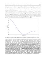
Figure 16-3 illustrates the normal torque-response characteristics of a V/Hz inverter.
Note that the ability of the drive to maintain high torque output at low speeds drops
off
significantly below
3
Hz.
For
this reason, the operating range
of
a V/Hz inverter is
usually less than
20
to 1 (i.e., 20: 1).
A
flux-vector control improves the drive’s dynamic response and may be able to con-
trol both the output torque and speed. Figure 164 provides a typical torque-speed
response curve of a flux-vector inverter.
Impact-Load Response
Inverter drives must compensate for variations in load. Figure 16-5 compares the
impact-load response
of
a standard V/Hz and a sensorless flux-vector-type inverter. In