Root Cause Failure Analysis Part 6 pot
Bạn đang xem bản rút gọn của tài liệu. Xem và tải ngay bản đầy đủ của tài liệu tại đây (1.31 MB, 30 trang )
142
Root
Cause
Failure
Analysis
ClWlkSMt
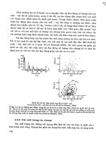
Figure
10-13
Three-piston compressor generates higher vibration levels
(Gibbs
1971).
installation
A
carefully planned and executed installation is extremely important and makes com-
pressor operation and maintenance easier and safer. Key components of a compressor
installation are location, foundation, and piping.
Location
The preferred location for any compressor
is
near the center
of
its load.
However, the choice often
is
influenced by the cost of supervision, which can vary by
location. The ongoing cost of supervision may be less expensive at a less-optimum
location, which can offset the cost
of
longer piping.
A
compressor always will give better, more reliable service when enclosed in a build-
ing that protects it from cold, dusty, damp, and corrosive conditions. In certain loca-
tions, it may be economical to use a roof only, but this is not recommended unless the
weather is extremely mild. Even then, it is crucial to prevent rain and wind-blown
debris from entering the moving parts. Subjecting a compressor to adverse inlet con-
ditions will dramatically reduce its reliability and significantly increase its mainte-
nance requirements.
Ventilation around a compressor is vital.
On
a motor-driven, air-cooled unit, the heat
radiated to the surrounding air is at least
65
percent
of
the power input. On a water-
Compressors
143
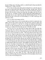
Figure
10-14
Opposed-piston compressor balances piston forces.
jacketed unit with an aftercooler and outside receiver, the heat radiated to the
sur-
rounding air may
be
15
to
25
percent of the total energy input, which still is
a
substan-
tial amount of heat. Positive outside ventilation is recommended for any compressor
room where the ambient temperature may exceed
104°F.
Foundation
Because of the alternating movement of pistons and other components.
reciprocating compressors often develop a shaking that alternates in direction. This
force must be damped and contained by the mounting. The foundation also must sup-
port the weight load of the compressor and its driver.
There are many compressor arrangements and the
net
magnitude of the moments and
forces developed can vary a great deal among them. In some cases, they are partially
or
completely balanced within the compressors themselves. In others, the foundation
must handle much of the force. When complete balance is possible, reciprocating
144
Root
Cause
Failure
Analysis
compressors can be mounted on a foundation just large and rigid enough to carry the
weight and maintain alignment. However, most reciprocating compressors require
larger, more massive foundations than other machinery.
Depending on the size and type of unit, the mounting may vary from simply bolting it
to the
floor
to
attaching to a massive foundation designed specifically for the applica-
tion.
A
proper foundation must
(1)
maintain the alignment and level of the compressor
and its driver at the proper elevation and
(2)
minimize vibration and prevent its trans-
mission to adjacent building structures and machinery. There are five steps to accom-
plish the first objective:
1.
The safe weight-bearing capacity of
the
soil must not be exceeded at any
point on the foundation base.
2.
The load to the
soil
must be distributed over the entire area.
3.
The size and proportion of the foundation block must be such that the
resultant vertical load due to the compressor, block, and any unbalanced
force falls within the base area.
4.
The foundation must have sufficient mass and weight-bearing area to pre-
vent its sliding on the soil due to unbalanced forces.
5.
Foundation temperature must be uniform to prevent warping.
Bulk is not usually the complete solution to foundation problems.
A
certain weight
sometimes is necessary, but soil area usually is of more value than foundation mass.
Determining if two
or
more compressors should have separate or single foundations
depends on the compressor type.
A
combined foundation is recommended for recipro-
cating units, since the forces from one unit usually will partially balance out the
forces from the others. In addition, the greater mass and surface area in contact with
the ground damps foundation movement and provides greater stability.
Soil quality may vary seasonally, and such conditions must be carefully considered in
the foundation design.
No
foundation should rest partially on bedrock and partially on
soil; it should rest entirely on one or the other. If placed on the ground, make sure that
part of the foundation does not rest on soil that has been disturbed. In addition, pilings
may be necessary to ensure stability.
Piping
Piping should easily
fit
the compressor connections without needing to
spring
or
twist it to fit. It must be supported independently of the compressor and
anchored, as necessary, to limit vibration and to prevent expansion strains. Improp-
erly installed piping may distort
or
pull the compressor’s cylinders
or
casing out of
alignment.
Air
Inlet
The intake pipe on an
air
compressor should be as short and direct as pos-
sible. If the total run
of
the inlet piping is unavoidably long, the diameter should be
increased. The pipe size should
be
greater than the compressor’s air-inlet connection.
Compressors
145
Cool
inlet air is desirable. For every
5°F
of ambient air temperature reduction, the vol-
ume
of
compressed air generated increases by 1 percent with the same power con-
sumption.
This
increase in performance is due to the greater density of the intake air.
It is preferable
for
the intake
air
to
be
taken
from
outdoors.
This
reduces heating and
air conditioning costs and, if properly designed, has fewer contaminants. However,
the intake piping should be a minimum of
6
ft above the ground and screened
or,
pref-
erably, filtered. An
air
inlet must be
free
of steam and engine exhaust. The inlet should
be hooded or turned down to prevent the entry
of
rain or snow. It should be above the
building eaves and several feet from the building.
Discharge
Discharge piping should
be
the full size of the compressor’s discharge
connection. The pipe size should not be reduced until the point along the pipeline is
reached where the flow has become steady and nonpulsating. With a reciprocating
compressor, this generally is beyond the aftercooler
or
the receiver. Pipes to handle
nonpulsating flow are sized by normal methods, and long-radius bends are recom-
mended. All discharge piping must
be
designed to allow adequate expansion loops
or
bends to prevent undue
stress
at the compressor.
Drainage
Before piping is installed, the layout should be analyzed to eliminate low
points where liquid could collect and to provide drains where low points cannot be
eliminated. A regular part of the operating procedure must
be
the periodic drainage of
low points in the piping and separators, as well as inspection
of
automatic drain traps.
Pressure-Relief
Valves
All reciprocating compressors must be fitted with pressure-
relief devices to limit the discharge
or
interstage pressures to a safe maximum for the
equipment served. Always install a relief valve capable
of
bypassing the full-load
capacity
of
the compressor between its discharge port and the first isolation valve. The
safety valves should be set to open at a pressure slightly higher than the normal dis-
charge-pressure rating of the compressor.
For standard
100
to
115
psig two-stage air
compressors, safety valves normally are set at 125 psig.
The pressure-relief safety valve normally is situated on top
of
the
air
reservoir, and
there must
be
no restriction on its operation. The valve usually
is
of
the “huddling
chamber” design, in which the
static
pressure acting on its disk area causes it to open.
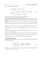
Figure
10-15
illustrates how such a valve functions. As the valve pops, the air space
within the huddling chamber between the seat and blowdown ring fills with pressur-
ized
air
and builds up more pressure on the roof of the disk holder.
This
temporary
pressure increases the upward thrust against the spring, causing the disk and its holder
to fully pop open.
Once a predetermined pressure drop (Le., blowdown) occurs, the valve closes with a
positive action by trapping pressurized air on
top
of
the disk holder. The pressure-
drop setpoint is adjusted by raising
or
lowering the blowdown ring. Raising the ring
increases the pressure-drop setting, while lowering it decreases the setting.
146
Root
Cause
Failure
Analysis
4.
WHEN THE VALVE
SETTlNG
IS
REACHED,
THE
POPPET
"OPENS"
7.
VENT CONNECTION
LIMITING PRESSURE PERMITS UNLOADING
.
IN
UPPER CHAMBER. PUMP THROUGH
RELIEF VALVE.
5.
WHEN THIS
PRESSURE
IS
20 psi
HIGHER THAN
IN
UPPER CHAMBER
.
2.
IS
SENSED
ABOVE
PISTON AND AT PILOT
'IVERT
OUTPUT
VALVE THROUGH
ORIFICE
IN
PISTON.
DIRECTLY
TO TANK.
WEWA
CLOSED
WA
CRACKED
RELIEW NG
Figure
10-15
Illustrates
how
a
safety
valve
functions.
Operating Methods
Compressors can be hazardous to work around because they have moving parts.
Ensure that clothing is kept away from belt drives, couplings, and exposed shafts. In
addition, high-temperature surfaces around cylinders and discharge piping are
exposed. Compressors are notoriously noisy,
so
ear protection should be worn. These
machines
are
used to generate high-pressure gas
so,
when working around them, it is
important to wear safety glasses and to avoid searching for leaks with bare hands.
High-pressure leaks can cause severe friction burns.
11
MIXERS
rxND
AGITATORS
Mixers are devices that blend combinations of liquids and solids into a homogenous
product. They come in a variety of sizes and configurations designed for specific
applications. Agitators provide the mechanical action to keep dissolved or suspended
solids in solution.
Both operate on basically the same principles, but variations in design, operating
speed, and applications divide the actual function of these devices. Agitators generally
work just as hard as mixers, and the terms often are used interchangeably.
CONFIGURATION
There are two primary types of mixers: propeller/paddle and screw. Screw mixers can
be further divided into batch and mixer-extruder types.
Propeller/Paddle
Propeller/paddle mixers are used to blend
or
agitate liquid mixtures in
tanks,
pipelines,
or
vessels. Figure 11-1 illustrates a typical top-entering propeller/paddle mixer. This
unit consists
of
an
electric motor, a mounting bracket, an extended shaft, and one
or
more impeller(s)
or
propeller(s). Materials
of
construction range from bronze to stain-
less steel, which are selected based on
the
particular requirements of the application.
The propeller/paddle mixer also is available in a side-entering configuration, which is
shown in Figure 11-2. This configuration typically is used to agitate liquids in large
vessels
or
pipelines. The side-entering mixer
is
essentially the same as the top-enter-
ing version except for the mounting configuration.
Both the top-entering and side-entering mixers may use either propellers, as shown
in
the preceding figures, or paddles, as illustrated by
Part
b
of
Figure 11-3. Generally.
147
148
Root
Cause Failure Analysis
Figure 11-1 Top-entering propeller-type mixer
(Thomas
Register 1995).
Figure 11-2 Side-entering propeller-type mixer
(Thomas
Register 1995).
Mixers
and
Agitators
149
Figure ZZ-3 Mixer can use eitherpropellers
or
paddles to provide
agitation
(Thomas Regis-
ter 1995).
propellers are used for medium-
to
high-speed applications where the viscosity is rel-
atively low. Paddles
are
used in low-speed, high-viscosity applications.
screw
The screw mixer uses
a
single- or dual-screw arrangement to mix liquids, solids, or a
combination of both. It comes in two basic configurations: batch and combination
mixer-extruder.
Butch
Figure
114
illustrates a typical batch-type screw mixer. This unit consists of
a
mix-
ing drum or cylinder, a single- or dual-screw mixer, and a power supply.
The screw configuration normally is either a ribbon-type helical screw or a series
of
paddles mounted on a common shaft. Materials
of
construction are selected based on
the specific application and materials to be mixed. Vpically, the screws are either
steel or stainless steel, but other materials are available.
Combination
Mixer-Extruder
The mixer-extruder combination unit shown in
Figure
11-5
combines the functions of
a mixer and
a
screw conveyor.
This
type of mixer is used for mixing viscous products.
150
Root
Cause Failure
Analysis
Figure 11-4 Batch-type mixer uses single or dual screws to
mix
product (Thomas Register
Z995).
PERFORMANCE
Unlike centrifugal pumps and compressors, few criteria can be used directly to deter-
mine mixer effectiveness and efficiency. However, the product quality and brake
horsepower
are
indices that can
be
used to indirectly gauge performance.
Product
Quality
The primary indicator of acceptable performance is the quality of the product deliv-
ered by the mixer. Although there is
no direct way to measure this indicator, feedback
from
the quality assurance
group
should
be
used
to
verify that acceptable perfor-
mance levels
are
attained.
Brake
Horsepower
Variation
in the actual brake horsepower required to operate a mixer
is
the primary
indicator of its performance envelope. Mixer design, whether propeller or screw type,
is
based on the viscosity of both the incoming and finished product. These variables
determine the brake horsepower required to drive the mixer, which will follow varia-
Figure
11-5
Combination
mixer-extruder (Thomas Register 1995).
Mixers
and Agitators
151
tions in the viscosity
of
the products being mixed.
As
the viscosity increases
so
will
the brake horsepower demand. Conversely, as the viscosity decreases,
so
will the
horsepower required to drive the mixer.
INSTALLATION
Installation
of
propeller-type mixers varies greatly, depending on the specific applica-
tion. Top-entering mixers utilize either a clamp- or flange-type mounting. It is inipor-
tant that the mixer be installed
so
the propeller
or
paddle is at a point within the tank,
vessel,
or
piping that assures proper mixing. Vendor recommendations found in O&M
manuals should be followed to ensure proper operation of the mixer.
Mixers should
be
mounted on a rigid base that assures level alignment and prevents
lateral movement of the mixer and its drivetrain. While most mixers can
be
bolted
directly to a base, care must be taken to ensure that the base is rigid and has the struc-
tural capacity to stabilize the mixer.
OPERATING
METHODS
There are only three major operating concerns for mixers: setup, incoming-feed rate.
and product viscosity.
Mixer
Setup
Both propeller and screw mixers have specific setup requirements. In the case of pro-
pelledpaddle-type mixers, the primary factor
is
the position of the propellers
or
pad-
dles within the tank
or
vessel. Vendor recommendations should he followed to assure
proper operation of the mixer.
If the propellers
or
paddles are too close to the liquid level. the mixer will create a
vortex that will entrain
air
and prevent adequate blending
or
mixing. If the propellers
are set too low, compress vortexing may occur. When this happens, the mixer will cre-
ate a stagnant zone in the area under the rotating assembly.
As
a result, some of the
product will settle in this zone and proper mixing cannot occur. Setting the mixer too
close to a comer
or
the side of the mixing vessel also can create a stagnant zone that
will prevent proper blending
or
mixing of the product.
For
screw-type mixers, proper clearance between the rotating element and the mixer
housing must be maintained to vendor specifications. If the clearance is improperly
set, the mixer will bind (i.e., not enough clearance)
or
fail to blend properly.
Feed
Rate
Mixers are designed
to
handle a relatively narrow band of incoming product flow rate.
Therefore. care must be exercised to ensure that the actual feed rate is maintained
152
Root
Cause
Failure
Analysis
within acceptable limits. The
O&M
manuals provided by the vendor will provide the
feed-rate limitations for various products. Normally, these rates must
be
adjusted for
viscosity and temperature variation.
Viscosity
Variations in viscosity of both the incoming and finished products have
a
dramatic
effect on mixer performance. Standard operating procedures should include specific
operating guidelines for the range of variation acceptable for each application. The
recommended range should include adjustments for temperature, flow rate, mixing
speed, and other factors that directly
or
indirectly affect viscosity.
DUST COLLECTORS
The basic operations performed by dust-collection devices are (1) separating particles
from the gas stream by deposition on a collection surface,
(2)
retaining the deposited
particles on the surface until removal, and
(3)
removing the deposit from the surface
for recovery
or
disposal.
The separation step requires
(1)
application of a force that produces a differential
motion
of
the particles relative to the gas and
(2)
sufficient gas-retention time for the
particles to migrate to the collecting surface. Most dust-collections systems are con-
stituted of a pneumatic-conveying system and some device that separates suspended
particulate matter from the conveyed airstream. The more common systems use either
filter media (e.g., fabric bags)
or
cyclonic separators to separate the particulate matter
from air.
BAGHOUSES
Fabric-filter systems, commonly called
bug-@fer
or
bughouse
systems,
are dust-col-
lection systems in which dust-laden
air
is passed through a bag-type filter. The bag
collects the dust in layers on its surface and the dust layer itself effectively becomes
the filter medium. Because the bag’s pores usually are much larger
than
those of the
dust-particle layer that forms, the initial efficiency is very low. However, efficiency
improves once an adequate dust layer forms. Therefore, the potential for dust penetra-
tion of the filter media is extremely low except during the initial period after startup,
bag change, or during the fabric-cleaning, or blow-down, cycle.
The principal mechanisms of disposition in dust collectors are
(1)
gravitational depo-
sition,
(2)
flow-line interception, (3) inertial deposition,
(4)
diffusional deposition,
and
(5)
electrostatic deposition. During the initial operating period, particle deposi-
tion takes place mainly by inertial and flow-line interception, diffusion, and gravity.
153
154
Root
Cause Failure Analysis
Once the dust layer has been fully established, sieving probably is the dominant depo-
sition mechanism.
Configuration
A
baghouse system consists of the following: a pneumatic-conveyor system, filter
media, a back-flush cleaning system, and a fan
or
blower to provide airflow.
Pneumatic
Conveyor
The primary mechanism for conveying dust-laden air to a central collection point is a
system of pipes
or
ductwork that functions as a pneumatic conveyor. This system
gathers dust-laden air from various sources within the plant and conveys it to the dust-
collection system. See the beginning of Chapter
9
for more information on pneu-
matic-conveyor systems.
Dust-Collection System
The design and configuration of the dust-collection system varies with the vendor and
the specific application. Generally, a system consists of either a single large hopper-
like vessel
or
a series of hoppers with a fan or blower affixed to the discharge mani-
fold. Inside the vessel is an inlet manifold that directs the incoming air or gas to the
dirty side of the filter media or bag.
A
plenum, or divider plate, separates the dirty and
clean sides of the vessel.
Filter media, usually long cylindrical tubes
or
bags, are attached to the plenum.
Depending on the design, the dust-laden air or gas may flow into the cylindrical filter
bag and exit to the clean side
or
it may flow through the bag from its outside and exit
through the tube’s opening. Figure
12-1
illustrates a typical baghouse configuration.
Fabric-filter designs fall into three types, depending on the method
of
cleaning used:
shaker cleaned, reverse-flow cleaned, and reverse-pulse cleaned.
Shaker-Cleaned Filter
The open lower ends of shaker-cleaned filter bags are fas-
tened over openings in the tube sheet that separates the lower, dirty-gas inlet chamber
from the upper, clean-gas chamber. The bags are suspended from supports that are
connected to a shaking device.
The dirty gas flows upward into the filter bag and the dust collects on the inside
sur-
face. When the pressure drop rises to a predetermined upper limit due to dust accumu-
lation, the gas flow is stopped and the shaker is operated. This process dislodges the
dust, which falls into a hopper located below the tube sheet.
For
continuous operation, the filter must
be
constructed with multiple compartments.
This
is
necessary
so
that individual compartments can be sequentially taken off-line
for cleaning while the other compartments continue to operate.
Dust
Collectors
155
Figure
12-1
A
Ordinary shaker-cleaned filters may be cleaned every
15
minutes to eight hours,
depending on the service conditions.
A
manometer connected across the filter is used
to determine the pressure drop, which indicates when the filter should be shaken.
Fully automatic filters may be shaken every
2
minutes, but bag maintenance is greatly
reduced if
the
time between shakings can be increased to
15
to
20
minutes.
The determining factor in the frequency of cleaning is the pressure drop.
A differen-
tial-pressure switch can serve as the actuator in automatic cleaning applications.
Cyclone precleaners sometimes are used to reduce the dust load on the filter or to
remove large particles before they enter the bag.
It is essential to stop the gas flow through the filter during shaking in order for the
dust to fall
off.
With very fine dust, it may be necessary to equalize the pressure
across the cloth. In practice, this can be accomplished without interrupting continu-
ous
operation by removing from service one section at a time. With automatic filters,
this operation involves closing the dirty-gas inlet dampers, shaking the filter units
either pneumatically or mechanically, and reopening the dampers. In some cases, a
reverse flow of clean gas through the filter is used to augment the shaker-cleaning
process.
156
Root
Cause
Failure
Analysis
The gas entering the filter must be kept above its dewpoint to avoid water-vapor con-
densation on the bags, which will cause plugging. However, fabric filters have been
used successfully in steam atmospheres, such as those encountered in vacuum dryers.
In these applications, the housing generally is steam cased.
Reverse-Flow-Cleaned Filter
Reverse-flow-cleaned filters are similar to the
shaker-cleaned design, except the shaker mechanism is eliminated. As with shaker-
cleaned filters, compartments are taken off-line sequentially for cleaning. The primary
use of reverse-flow cleaning is in units using fiberglass-fabric bags at temperatures
above
150°C
(300°F).
After the dirty-gas flow is stopped, a fan forces clean gas through the bags from the
clean-gas side. The superficial velocity of the gas through the bag generally is
1.5
to
2.0
ft
per minute, or about the same velocity as the dirty-gas inlet flow. This flow of
clean gas partially collapses the bag and dislodges the collected dust, which falls into
the hopper. Rings usually are sewn into the bags at intervals along their length to pre-
vent complete collapse, which would obstruct the fall of the dislodged dust.
Reverse-Pulse-Cleaned Filter
In the reverse-pulse-cleaned filter, the bag forms a
sleeve drawn over a cylindrical wire cage, which supports the fabric on the clean-gas
side (Le., inside) of the bag. The dust collects on the outside
of
the bag.
A venturi nozzle is located in the clean-gas outlet
from
each bag, which is used for
cleaning.
A
jet of high-velocity air is directed through the venturi nozzle and into the
bag, which induces clean gas to pass through the fabric to the dirty side. The high-
velocity jet is released in a short pulse, usually about 100 milliseconds, from a com-
pressed air line by a solenoid-controlled valve. The pulse of air and clean gas expand
the bag and dislodge the collected dust. Rows of bags are cleaned in a timed sequence
by programmed operation of the solenoid valves. The pressure of the pulse must be
sufficient to dislodge the dust without ceasing gas flow through the baghouse.
It is common practice to clean the bags on-line without stopping the flow of dirty gas
into the filter. Therefore, reverse-pulse bag filters often are built without multiple
compartments. However, investigation has shown that a large fraction of the dislodged
dust redeposits on neighboring bags rather than falls into the dust hopper.
As a result, there is
a
growing trend to clean reverse-pulse filters off-line by using
bags with multiple compartments. These sections allow the outlet-gas plenum serving
a particular section to be closed
off
from the clean-gas exhaust, thereby stopping the
flow of inlet gas. On the dirty-side of the tube sheet, the isolated section is separated
by partitions from neighboring sections where filtration continues. Sections of the fil-
ter are cleaned in rotation as with shaker and reverse-flow filters.
Some manufacturers design bags for use with relatively low-pressure air (i.e.,
15
psi)
instead of the normal
100
psi air. This allows them to eliminate the venturi tubes for
Dust
Collectors
157
clean-gas induction. Others have eliminated the separate jet nozzles located at the
individual bags in favor of a single jet to pulse
air
into the outlet-gas plenum.
Reverse-pulse filters typically are operated at higher filtration velocities (i.e., air-to-
cloth ratios) than shaker
or
reverse-flow designs. Filtration velocities may range from
3
to 15 ft per minute in reverse-pulse applications, depending on the dust being col-
lected. However, the most commonly used range is
4-5
ft
per minute.
The frequency of cleaning depends on the nature and concentration of the dust. Typi-
cal cleaning intervals vary from about
2
to 15 min. However, the cleaning action of
the pulse is
so
effective that the dust layer may be completely removed from the sur-
face
of
the fabric. Consequently, the fabric itself must serve as the principal filter
media for a substantial part of the filtration cycle, which decreases cleaning efficiency.
Because of this, woven fabrics are unsuitable
for
use
in
these devices and felt-type
fabrics are used instead. With felt filters, although the bulk of the dust still is removed,
an adequate level of dust collection is provided by the fabric until the dust layer
reforms.
Cleaning System
As
discussed in the preceding section, filter bags must be cleaned periodically to
prevent excessive buildup of dust and to maintain an acceptable pressure drop across
the filters. Two of the three designs discussed, reverse-flow and reverse-pulse,
depend on an adequate supply of clean air or gas to provide this periodic cleaning.
Two factors are critical in these systems: the clean-gas supply and the proper clean-
ing frequency.
Clean-Gas Supply
Most applications that use the reverse-flow cleaning system use
ambient
air
as the primary supply of clean gas. A large fan
or
blower draws ambient
air into the clean side of the filter bags. However, unless the air
is
properly condi-
tioned by inlet filters, it may contain excessive dirt loads that can affect the bag life
and efficiency of the dust-collection system.
In reverse-pulse applications, most plants rely on plant-air systems as the source for
the high-velocity pulses required for cleaning. In many cases, however, the plant-air
system is insufficient for this purpose. Although the pulses required are short (i.e.,
100
milliseconds
or
less), the number and frequency can deplete the supply. Therefore,
care must be taken to ensure that both sufficient volume and pressure are available to
achieve proper cleaning.
Cleaning Frequency
Proper operation of a baghouse, regardless of design, depends
on frequent cleaning of the filter media. The system is designed to operate within a
specific range of pressure drops that defines clean and fully loaded filter media. The
cleaning frequency must assure that the maximum recommended pressure drop is not
exceeded.
158
Root
Cause
Failure
Analysis
This can be a real problem for baghouses that rely on automatic timers to control
cleaning frequency. The use of a timing function to control cleaning frequency is not
recommended unless the dust load is known to be consistent.
A
better approach is to
use differential-pressure gauges to physically measure the pressure drop across the fil-
ter media to trigger the cleaning process based on preset limits.
Fan
or Blower
All baghouse designs use some form of fan, blower, or centrifugal compressor to pro-
vide the dirty-air flow required for proper operation. In most cases, these units are
installed on the clean side of the baghouse to draw the dirty
air
through the filter media.
Since these units provide the motive power required to transport and collect the dust-
laden air, their operating condition is critical to the baghouse system. The type and
size of air-moving unit varies with the baghouse type and design. Refer to the
O&M
manuals, as well as Chapters
8
(Fans, Blowers, and Fluidizers) and
10
(Compressors)
for specific design criteria for these critical units.
Performance
The primary measure of baghouse-system performance is its ability to consistently
remove dust and other particulate matter from the
dirty
airstream. Pressure drop and
collection efficiency determine the effectiveness of these systems.
Pressure Drop
The
filtration,
or
superficial face, velocities used in fabric filters generally are in the
range of
1-10
ft per minute, depending on the type of fabric, fabric supports, and
cleaning methods used. In this range, pressure drops conform to Darcy’s law for
streamline flow in porous media, which states that the pressure drop is directly pro-
portional to the flow rate. The pressure drop across the fabric media and the dust layer
may be expressed by
where
Ap
=
pressure drop (in. of water);
V’
=
superficial velocity through filter (ft/min);
o
=
dust loading on filter (lbdft’);
K,
=
resistance coefficient for conditioned fabric (inches of water/foot/
K2
=
resistance coefficient for dust layer (in. of water/lbdft/min).
minute)
;
Conditioned fabric maintains a relatively consistent dust-load deposit following a
number of filtration and cleaning cycles.
K,
may be more than ten times the value of
the resistance coefficient for the original clean fabric. If the depth of the dust layer on
Dust
Collectors
159
the fabric is greater than about
g6
in. (which corresponds to a fabric dust loading on
the order of
0.1
Ibrdft’), the pressure drop across the fabric, including the dust in the
pores, usually is negligible relative to that across the dust layer alone.
In practice,
K,
and
K2
are measured directly in filtration experiments. These values
can
be
corrected for temperature by multiplying the ratio of the gas viscosity at the
desired condition to the gas viscosity at the original experimental condition.
Collection Eficiency
Under controlled conditions (e.g., in the laboratory), the inherent collection efficiency
of fabric filters approaches
100
percent. In actual operation, it is determined by sev-
eral variables, in particular the properties of the dust to be removed, choice of filter
fabric, gas velocity, method of cleaning, and cleaning cycle. Inefficiency usually
results from bags that are poorly installed, tom,
or
stretched from excessive dust load-
ing and excessive pressure drop.
Installation
Most baghouse systems
are
provided as complete assemblies by the vendor. While the
unit may require some field assembly, the vendor generally provides the structural
supports, which
in
most cases are adequate. The only controllable installation factors
that may affect performance are the foundation and connections to pneumatic convey-
ors
and other supply systems.
Foundation
The foundation must support the weight of the baghouse. In addition, it must absorb
the vibrations generated by the cleaning system. This is especially true when using
the shaker-cleaning method, which can generate vibrations that can adversely affect
the structural supports, foundation, and adjacent plant systems.
Connections
Efficiency and effectiveness depend
on
leak-free connections throughout the system.
Leaks reduce the system’s ability to convey dust-laden
air
to the baghouse. One
potential source for leaks is improperly installed filter bags. Because installation var-
ies with the type
of
bag and baghouse design, consult the vendor’s
O&M
manual for
specific instructions.
Operating Methods
The guidelines provided in the vendor’s
0&M
manual should be the primary refer-
ence for proper baghouse operation. Vendor-provided information should be used
because there are few common operating guidelines among the various configura-
tions. The only general guidelines applicable to most designs are cleaning frequency
and inspection and replacement of filter media.
160
Root
Cause Failure Analysis
Cleaning
As previously indicated, most bag-type filters require a precoating of particulates
before they can effectively remove airborne contaminates. However, particles can
completely block airflow if the filter material becomes overloaded. Therefore, the pri-
mary operating criterion is to maintain the efficiency of the filter media by controlling
the cleaning frequency.
Most systems use a time-sequence to control the cleaning frequency. If the particulate
load entering the baghouse is constant, this approach would be valid. However, the
incoming load generally changes constantly. As a result, the straight time-sequence
methodology does not provide the most efficient mode of operation.
Operators should monitor the differential-pressure gauges that measure the total pres-
sure drop across the filter media. When the differential pressure reaches the maximum
recommended level (data provided by the vendor), the operator should override any
automatic timer controls and initiate the cleaning sequence.
Inspecting and Replacing Filter Media
Filter media used in dust-collection systems are prone to damage and abrasive wear.
Therefore, regular inspection and replacement is needed to ensure continuous, long-
term performance. Any damaged, tom, or improperly sealed bags should be removed
and replaced.
A common problem associated with baghouses is improper installation of filter
media. Therefore, it is important to follow the instructions provided by the vendor. If
the filter bags are not properly installed and sealed, overall efficiency and effective-
ness are significantly reduced.
CYCLONE
SEPARATORS
A widely used type of dust-collection equipment is the cyclone separator. A “cyclone”
essentially is a settling chamber
in
which gravitational acceleration is replaced by cen-
trifugal acceleration. Dust-laden air
or
gas enters a cylindrical or conical chamber tan-
gentially at one
or
more points and leaves through a central opening. The dust
particles, by virtue of their inertia, tend to move toward the outside separator wall from
which they are led into a receiver. Under common operating conditions, the centrifugal
separating force or acceleration may range from five times gravity in very large diame-
ter, low-resistance cyclones to 2,500 times gravity in very small, high-resistance units.
Within the range of their performance capabilities, cyclones are one of the least expen-
sive dust-collection systems. Their major limitation is that, unless very small units are
used, efficiency is low
for
particles smaller than five microns. Although cyclones may
be used to collect particles larger than 200 microns, gravity-settling chambers
or
sim-
ple inertial separators usually
are
satisfactory and less subject to abrasion.
Dust Collectors
161
Configuration
The internal configuration of a cyclone separator
is
relatively simple. Figure 12-2
illustrates a typical cross-section of a cyclone separator, which consists of the follow-
ing segments:
Inlet area that causes the gas to flow tangentially,
Cylindrical transition area,
Decreasing taper that increases the air velocity as the diameter decreases,
Central return tube
to
direct the dust-free air out the discharge port.
Particulate material is forced to the outside
of
the tapered segment and collected
in
a
drop-leg located at the dust outlet. Most cyclones have a rotor-lock valve affixed to
the bottom of the drop-leg.
This
is a motor-driven valve that collects the particulate
material and discharges it into a disposal container.
performance
Performance
of
a cyclone separator is determined
by
flow pattern, pressure drop, and
collection efficiency.
LOwf
outlet
Figure
12-2
Flow
pattern
through
a
lypical
cyclone
separator
(Perry
and
Green
1984).
162
Root
Cause
Failure
Analysis
Flow Pattern
The path the gas takes in a cyclone is through a double vortex that spirals the gas
downward at the outside and upward at the inside. When the gas enters the cyclone,
the tangential component of its velocity,
V,,,
increases with the decreasing radius
as
expressed by
In this equation,
r
is the cyclone radius and
n
is dependent on the coefficient
of
fric-
tion. Theoretically, in the absence of wall friction,
n
should equal
1.0.
Actual mea-
surements, however, indicate that
n
ranges from
0.5
to
0.7
over a large portion of the
cyclone radius. The spiral velocity in a cyclone may reach a value several times the
average inlet-gas velocity.
Pressure Drop
The pressure drop and the friction loss through a cyclone are most conveniently
expressed in terms of the velocity head based on the immediate inlet area. The inlet
velocity head,
h,,,
which is expressed in inches of water, is related to the average
inlet-gas velocity and density by
h,,
=
0.0030r
V,'
where
h,,,
=
inlet-velocity head (in. of water);
r
=
gas density (Ib/ft');
V,
=
average inlet-gas velocity (ft/sec).
The cyclone friction loss,
F,,,
is a direct measure of the static pressure and power that
a fan must develop. It is related to the pressure drop by
where
F,,,
Ap,,
=
pressure drop through the cyclone (inlet-velocity heads);
A,
D,
=
friction loss (inlet-velocity heads);
=
area of the cyclone (ft2);
=
diameter of the gas exit (ft).
The friction loss through cyclones may range from
1
to
20
inlet-velocity heads,
depending on its geometric proportions. For
a
cyclone of specific geometric propor-
tions,
F,,
and
Ap,,?
essentially are constant and independent
of
the actual cyclone size.
Dust
Collectors
163
Collection Ejiciency
Since cyclones rely on centrifugal force to separate particulates from the air or gas
stream, particle mass is the dominant factor that controls efficiency.
For
particulates
with high densities (e.g., ferrous oxides), cyclones can achieve
99
percent
or
better
removal efficiencies, regardless of particle size. Lighter particles (e.g., tow or flake)
dramatically reduce cyclone efficiency.
These devices generally are designed to meet specific pressure-drop limitations. For
ordinary installations operating at approximately atmospheric pressure, fan limita-
tions dictate a maximum allowable pressure drop corresponding to a cyclone inlet
velocity in the range of
20-70
ft
per second. Consequently, cyclones usually
are
designed for an inlet velocity of
50
ft
per second.
Varying operating conditions change dust-collection efficiency by only a small
amount. The primary design factor that controls collection efficiency is cyclone diam-
eter.
A
small-diameter unit operating at a fixed pressure drop has a higher efficiency
than a large-diameter unit. Reducing the gas-outlet duct diameter also increases the
collection efficiency.
Installation
As in any other pneumatic-conveyor system, special attention must be given to the
piping
or
ductwork used to convey the dust-laden air
or
gas. The inside surfaces must
be smooth and free of protrusions that affect the flow pattern. All bends should be
gradual and provide a laminar-flow path for the gas. See the appropriate section in
Chapter
9
for specific installation information on pneumatic conveyors.
Cyclones are designed for continuous operation and must be protected from plugging.
In intermittent applications, the operating practices must include specific steps to
purge the entire system of particulates prior to shutdown.
Pressure drop
is
the only factor that can be effectively controlled by an operator.
Using the fan dampers, the operator can increase
or
decrease the cyclone’s load by
varying the velocity of the entering dirty air.
PROCESS
ROLLS
Many types of process
rolls
are used in industrial applications. However, all share
common design, installation, and operating criteria, and this chapter provides a practi-
cal review
of
their design and application. In general, rolls can be divided into two
major classifications: working and conveying.
Working
rolls
change the product being processed through the production system.
Included in this classification are printing rolls, which transfer a pattern to
the
prod-
uct; corrugating rolls used to impart a profile to the product; bridle rolls, which pro-
vide torsional power to drive the product through the process; and work rolls used by
the metal-processing industry to change product thickness and shape.
Conveying
rolls
transport the product
from
one point to another. This type
of
roll
ranges from small-diameter, nondriven
rolls
used in simple conveyors to large-diame-
ter, driven rolls used to transport steel, paper, and a variety
of
other products through
continuous-process lines.
CONFIGURATION
All process rolls are composed of the following parts: body, face, neck, and bearing-
support shafts. Figure
13-1
illustrates a typical process roll used in continuous-pro-
cess lines.
Body
Depending on the specific application, the
roll
body may be constructed
of
a variety
of materials. Typically, cast iron or steel is used, but more exotic materials, such as
Monel, stainless steel,
or
bronze, may be used
for
certain applications.
164
Process
Rolls
165
Roll
Figure
13-1
Typical
process
roll.
Conveying-roll bodies normally are cylindrical, but work-roll bodies may have a vari-
ety of shapes
or
profiles. In many of these applications, the roll body will have a spe-
cific profile, commonly referred to as a
crown,
that enhances the work performed by
the roll. The profiles range from convex to concave, which determines the force trans-
mission the roll provides.
Face
The roll face is the surface of the roll body. This is the area that performs work. Typi-
cally, the roll face is ground and polished to provide a smooth surface that does not
affect the product when it is in contact with the roll.
A
variety of finishing techniques are used to prepare the roll face. In work-roll appli-
cations, the face may be chrome plated, rubber coated, etched, or corrugated. The fin-
ishing method is determined by the specific application and the work to be performed.
For
example, coatings such
as
rubber commonly are used to increase friction between
the roll face and the transported product.
A
corrugated surface is used to impart a pat-
tern to the product (e.g., paper towels).
Neck
The neck is the transition area on both ends of the roll body that reduces the roll’s
diameter to that of the bearing-support shafts. The design methodology used for roll-
neck construction varies with the intended function of the roll.
For
example, rolls used
in a cold-reduction mill have a cast-steel body and neck. Because the roll must bend
in normal operation, the necks are not hardened, to facilitate bending.
Neck design is critical to roll reliability, and many failures can be directly attributed to
poor design. On large-diameter rolls, the reduction in diameter
from
the
body
to the
final shaft size should be in steps rather than
as
a single reduction. Each step down
should have stress-relief cuts at the transition points to prevent stress failure. Smaller-
diameter rolls can
be
reduced in a single step, but they also must have stress relief by
undercutting to prevent failure.
166
Root
Cause
Failure
Analysis
Bearing-Support Shafts
Many roll failures can be directly attributed to poor shaft design. In these cases, the
total
span
from the
roll
body to the bearing-support point
is
too long for the shaft
diameter.
As
a result, the bending moment imparted by the roll during normal opera-
tion creates an alternating compression-tension stress on the shafts. The typical failure
point is where the shaft diameter changes.
Both the total bearing span from inboard to outboard bearing and the cantilevered
spans from the roll body
to
the bearing-support point must be carefully considered
when designing a process roll. The design must withstand the total forces generated in
both normal and abnormal operation.
The fact that roll necks generally are relatively long and use multiple shaft-diameter
reductions causes two problems. First, the
long
span and reduced diameter weaken
the shaft, increasing the probability of excessive bending and the potential for prema-
ture failure. The second problem is the
90"
corner created by the diameter reduction.
This comer creates stress points that work harden when the roll is subjected to bend-
ing moments and strip tension.
A
good
design limits the number of shaft-diameter reductions and eliminates the
90"
comers by filleting these transition points.
This
approach removes the stress points
created by sharp corners and increases the strength of the shaft. Figure
13-2
illus-
trates the proper way to reduce a shaft's diameter using a stress-relief radius.
It is important to visually inspect process rolls. Poorly designed
rolls
and those used
in improperly monitored applications are highly susceptible to premature failure.
Rolls with multiple shaft reductions with
or
without
90"
corners at these reductions
warrant special attention in a predictive-maintenance program.
It
is important to care-
fully monitor strip tension, the amount of roll deflection
or
bending, and any other
load that may be present.
Figure
13-2
Diameter reduction of
a
shfl
using
a
stress-relief radius.