Root Cause Failure Analysis Part 5 pdf
Bạn đang xem bản rút gọn của tài liệu. Xem và tải ngay bản đầy đủ của tài liệu tại đây (1.48 MB, 30 trang )
CONVEYORS
Conveyors are used to transport materials from one location to another within a plant
or facility. The variety of conveyor systems is almost infinite, but the two major classi-
fications used in typical chemical plants
are
pneumatic and mechanical. Note that the
power requirements of a pneumatic-conveyor system are much greater than for a
mechanical conveyor
of
equal capacity. However, both systems offer some advantages.
PNEUMATIC
Pneumatic conveyors are used to transport dry, free-flowing, granular material in sus-
pension within a pipe or duct. This is accomplished by the use
of
a high-velocity
air-
stream or by the energy
of
expanding compressed
air
within a comparatively dense
column of fluidized or aerated material. Principal uses are
(1)
dust collection;
(2)
con-
veying
soft
materials, such as flake or tow; and (3) conveying hard materials, such as
fly ash, cement, and sawdust.
The primary advantages of pneumatic-conveyor systems are the flexibility of piping
configurations and their ability to greatly reduce the explosion hazard. Pneumatic
conveyors can be installed in almost any configuration required to meet the specific
application. With the exception
of
the primary driver, there are no moving parts that
can fail or cause injury. However, when used to transport explosive materials, the
potential for static charge buildup that could cause an explosion remains.
Configuration
A
typical pneumatic-conveyor system consists of Schedule-40 pipe or ductwork,
which provides the primary flow path used to transport the conveyed material. Motive
power is provided by the primary driver, which can be either a fan, fluidizer, or posi-
tive-displacement compressor.
112
Conveyors
113
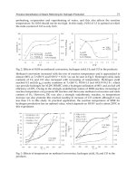
performance
Pneumatic conveyor performance is determined by the following factors: primary-
driver output, internal surface of the piping
or
ductwork, and the condition of the
transported material. Specific factors affecting performance include motive power,
friction loss. and flow restrictions.
Motive Power
The motive power is provided by the primary driver, which generates the gas (typi-
cally air) velocity required to transport material within
a
pneumatic-conveyor system.
Therefore, the efficiency
of
the conveying system depends
on
the primary driver's
operating condition.
Friction
Loss
Friction loss within a pneumatic-conveyor system is a primary source
of
efficiency
loss. The piping
or
ductwork must
be
properly sized to minimize friction without low-
ering the velocity below the value needed to transport the material.
Flow Restrictions
An inherent weakness of pneumatic-conveyor systems is their potential for blockage.
The inside surfaces must
be
clean and free
of
protrusions
or
other defects that can
restrict
or
interrupt the flow of material. In addition, when a system
is
shut down
or
the velocity
drops
below the minimum required to keep the transported material sus-
pended, the product will
drop
out
or
settle in the piping
or
ductwork. In most cases,
this settled material will compress and lodge in the piping. The restriction caused by
this compacted material will reduce flow and eventually result in a complete blockage
of
the system.
Another major contributor to flow restrictions is blockage caused by system backups.
This occurs when the end point of the conveyor system (i.e., storage silo, machine,
or
vessel) cannot accept the entire delivered flow of material.
As
the transported material
backs up in the conveyor piping, it compresses and forms
a
solid plug that must be
removed manually.
Installation
All piping and ductwork should be
as
straight and short as possible. Bends should
have a radius
of
at least three diameters
of
the pipe
or
ductwork. The diameter should
be selected to minimize friction loss and maintain enough velocity to prevent settling
of
the conveyed material. Branch lines should be configured to match as closely
as
possible the primary flow direction and avoid
90"
angles to the main line. The area
of
the main conveyor line at any point along its run should be
20
to
25
percent greater
than the sum
of
all its branch lines.
114
Root
Cause
Failure
Analysis
When vertical runs are short in proportion to the horizontal runs, the size of the riser
can be restricted to provide the additional velocity, if needed. If the vertical runs are
long, the primary or a secondary driver must provide sufficient velocity to transport
the material.
Cleanouts, or drop-legs, should be installed at regular intervals throughout the system
to permit foreign materials to drop out of the conveyed material. In addition, they pro-
vide the means to remove materials that drop out when the system is shut down or air
velocity is lost. It is especially important to install adequate cleanout systems near
flow restrictions and
at
the end of the conveyor system.
Operating Methods
Pneumatic-conveyor systems must be operated properly to prevent chronic problems,
with the primary concern being to maintain constant flow and velocity. If either of
these variables is permitted to drop below the system’s design envelope, partial or
complete blockage of the conveyor system will occur.
Constant velocity can be maintained only when the system is operated within its per-
formance envelope and when regular cleanout is part of the normal operating practice.
In addition, the primary driver must be in good operating condition. Any deviation in
the primary driver’s efficiency reduces the velocity and can result in partial or com-
plete blockage.
The entire pneumatic-conveyor system should
be
completely evacuated before shut-
down to prevent material from settling in the piping or ductwork.
In
noncontinuous
applications, the conveyor system should be operated until all material within the con-
veyor’s piping is transported to its final destination. Material that is allowed to settle
will compact and partially block the piping. Over time, this will cause a total blockage
of the conveyor system.
MECHANICAL
A variety of mechanical-conveyor systems are used in chemical plants. These systems
generally incorporate chain- or screw-type mechanisms.
Chain
A
commonly used chain-type system is a flight conveyor (e.g., Hefler conveyor),
which is used to transport granular, lumpy,
or
pulverized materials along a horizontal
or inclined path within totally enclosed ductwork. The Hefler systems generally have
lower power requirements than the pneumatic conveyor and, in addition, prevent
product contamination. This section focuses primarily on the Hefler-type conveyor
because it is one of the most commonly used systems.
Conveyors
115
Table
%I
Approximate Capacities
of
Hejler Conveyors
Flight Width
and Depth
(in.)
12x6
15x6
18x6
24
x
8
30x
10
36x 12
Quantity
of
Material
cftm
0.40
0.49
0.56
1.16
1.60
2.40
Approximate
Capacity
(short
tonshour)
60
13
84
174
240
360
Lump Size,
Single Strand Lump
Size,
Dual
(in.)
Strand (in.)
31.5 4.0
41.5
5
.O
5.0 6.0
10.0
14.0
16.0
Source: Theodore Baumeister, ed Marks’
Standard
Handbook
for
Mechanical Engineers, 8th
ed.
(New
York: McGraw-Hill. 1978).
Configuration
The Hefler-type conveyor uses a center-
or
double-chain configuration to provide pos-
itive transfer of material within its ductwork. Both chain configurations use hardened
bars or U-shaped devices that are an integral part of the chain to drag the conveyed
material through the ductwork.
Peqonnance
Data used to determine Hefler conveyors’ capacity and the size of material that can be
conveyed are presented in Table 9-1. Note that the data are for level conveyors. When
conveyors are inclined, the capacity data obtained from Table 9-1 must be multiplied
by the factors provided in Table
9-2.
Installation
The primary installation concerns with Hefler-type conveyor systems are the duct-
work and primary-drive system.
Ductwork The inside surfaces of the ductwork must be free of defects
or
protrusions
that interfere with the movement
of
the conveyor’s chain or transported product.
This
is especially true at the joints. The ductwork must be sized to provide adequate chain
Table
9-2
Capac?y Correction
Factors
for
Inclined Hefler Conveyors
Inclination,
degrees
20
25
30
35
Factor
0.9 0.8
0.7
0.6
Source: Theodore Baumeister,
ed
Marks’
Standard
Handbook
for
Mechanical Engineers, 8th
ed.
(New
York: McCraw-Hill, 1978).
116
Root
Cause
Failure
Analysis
clearance but should not be large enough to have areas where the chain-drive bypasses
the product.
A long horizontal run followed by an upturn is inadvisable because of radial thrust.
All bends should have a large radius to permit smooth transition and prevent material
buildup.
As
with pneumatic conveyors, the ductwork should include cleanout ports at
regular intervals for ease of maintenance.
Primary Drive System
Most mechanical conveyors use a primary-drive system that
consists of an electric motor and a speed-increaser gearbox. See Chapter
14
for more
information on gear-drive performance and operation criteria.
The drive-system configuration may vary, depending on the specific application
or
vendor. However, all configurations should include a single point-of-failure device,
such as a shear pin, to protect the conveyor. The shear pin is critical in this type of
conveyor because it is prone to catastrophic failure caused by blockage
or
obstruc-
tions that may lock the chain. Use of the proper shear pin prevents major damage to
the conveyor system.
For
continuous applications, the primary-drive system must have adequate horsepower
to handle a fully loaded conveyor. Horsepower requirements should be determined
based on the specific product’s density and the conveyor’s maximum-capacity rating.
For
intermittent applications, the initial startup torque
is
substantially greater than for
continuous operation. Therefore, selection of the drive system and the designed fail-
ure point of the shear device must be based on the maximum startup torque of a fully
loaded system.
If either the drive system
or
designed failure point is not properly sized, this type of
conveyor is prone to chronic failure. The predominant types of failure are frequent
breakage
of
the shear device and trips
of
the motor’s circuit breaker caused by exces-
sive startup amp loads.
Operating
Methods
Most mechanical conveyors are designed for continuous operation and may exhibit
problems in intermittent-service applications. The primary problem is the startup
torque for a fully loaded conveyor. This is especially true for conveyor systems han-
dling material that tends to compact or compress on settling in a vessel, such as the
conveyor trough.
The only positive method of preventing excessive startup torque is to ensure that the
conveyor is completely empty before shutdown. In most cases, this can be accom-
plished by isolating the conveyor from its supply for a few minutes prior to shutdown.
This time delay permits the conveyor to deliver its entire load of product before it is
shut
off.
Conveyors
117
In applications where
it
is impossible to completely evacuate the conveyor prior to
shutdown, the only viable option is to jog,
or
step start, the conveyor. Step starting
reduces the amp load on the motor and should control the torque to prevent the shear
pin from failing.
If,
instead of step starting, the operator applies full motor load to a stationary, fully
loaded conveyor, one of two things will occur:
(1)
the drive motor's circuit breaker
will trip as a result of excessive amp load
or
(2)
the shear pin installed to protect the
conveyor will fail. Either of these failures adversely affects production.
Screw
The screw,
or
spiral, conveyor is widely used for pulverized
or
granular, noncorrosive,
nonabrasive materials in systems requiring moderate capacities, distances no more
than about
200
feet, and moderate inclines
(535").
It usually costs substantially less
than any other type of conveyor and can be made dust tight by installing a simple
cover plate.
Abrasive
or
corrosive materials can be handled with suitable construction of the helix
and trough. Conveyors using special materials, such as hard-faced cast iron and lin-
ings
or
coatings, on the components that come into contact with the materials can be
specified in these applications. The screw conveyor will handle lumpy material if the
lumps are not large in proportion to the diameter
of
the screw's helix.
Screw conveyors may
be
inclined. A standard-pitch helix will handle material on
inclines up to
35".
Capacity is reduced in inclined applications, and Table
9-3
pro-
vides the approximate reduction in capacity for various inclines.
Configuration
Screw conveyors have a variety of configurations. Each is designed for specific appli-
cations
or
materials. Standard conveyors have a galvanized-steel rotor,
or
helix, and
trough. For abrasive and corrosive materials (e.g wet ash), both the helix and trough
may be hard-faced cast iron. For abrasives, the outer edge of the helix may
be
faced
with a renewable strip of Stellite(tm) (a cobalt alloy produced by Haynes Stellite Co.)
or
other similarly hard material. Aluminum, bronze, Monel,
or
stainless steel also may
be
used to construct the rotor and trough.
Table
9-3
Screw Conveyor Capacity Reductions
for
Znclined Applications
Inclination, degrees
LO
15
20
25
30
35
Reductionincapacity,
8
10
26
45
58 70 78
Source:
Theodore Baumeister.
ed.,
Marks' Standard Handbook for Mechanical Engineers,
8th
ed. (New
York:
McGraw-Hill,
1978).
11s
Root
Cause
Failure
Analysis
Short-Pitch Screw
The standard helix used for screw conveyors has a pitch approximately equal to its
outside diameter. The short-pitch screw is designed for applications with inclines
greater than
29".
Variable-Pitch Screw
Variable-pitch screws having the short pitch at the feed-end automatically control the
flow to the conveyor and correctly proportion the load down the screw's length.
Screws having what is referred to as a
short section,
which has either a shorter pitch
or smaller diameter, are self-loading and do not require a feeder.
Cut
Flight
Cut-flight conveyors are used for conveying and mixing cereals, grains, and other
light material. They are similar to normal flight or screw conveyors, and the only dif-
ference is the configuration of the paddles
or
screw. Notches are cut in the flights to
improve the mixing and conveying efficiency when handling light,
dry
materials.
Ribbon Screw
Ribbon screws are used for wet and sticky materials, such as molasses, hot tar, and
asphalt.
This
type of screw prevents the materials from building up and altering the
natural frequency of the screw. A buildup can cause resonance problems and possibly
catastrophic failure
of
the unit.
Paddle Screw
The paddle-screw conveyor is used primarily for mixing materials like mortar and
paving mixtures. An example of a typical application is churning ashes and water to
eliminate dust.
Performance
Process parameters, such as density, viscosity, and temperature, must be constantly
maintained within the conveyor's design operating envelope. Slight variations can
affect performance and reliability. In intermittent applications, extreme care should be
taken to fully evacuate the conveyor prior
to
shutdown. In addition, caution must be
exercised when restarting a conveyor in case an improper shutdown was performed
and material was allowed to settle.
Power Requirements
The horsepower requirement for the conveyor-head shaft,
H,
for horizontal screw
conveyors can be determined from the following equation:
H=
(Am+
CWLF)
X
10-6
Conveyors
119
Table
9-4
Factor
A
for Self-Lubricating Bronze Bearings
ConveyorDiameter,in. 6 9 10
12 14 16 18
20
24
Factor
A
54 96 114 171 255 336
414 510
690
Source:
Theodore
Baumeister, ed.,
Marks’ Standard Handbook for Mechanical Engineers.
8th
ed.
(New
York: McGraw-Hill, 1978).
where
A
=
factor for size
of
conveyor (see Table
9-4);
c
=
material volume,
ft3/h;
F
=
material factor, unitless (see Table
9-5);
L
=
length of conveyor,
ft;
N
=
conveyor rotation speed (rpm);
W
=
density
of
material, Ib/ft3.
Table
9-5
Power Requirements by Material Group
Max.
Cross-Section
(a)
Max.
Density
Max.
rpm
for
Max.
rpm
Material
Occupied
by
the
of
Material
6-in.
for
20-in.
Group
Material
Ob@)
diameter diameter
1
45 50 170 110
2
38
50 I20 75
3
31
75 90 60
4 25
100
70
50
5 12 112
30
25
Group
1:
F
factor is
0.5
for
light materials such
as
barley, beans, brewers, grains (dry), coal (pulv.), corn
meal, cottonseed meal, flaxseed,
flour,
malt, oats, rice, wheat.
Group
2:
Includes fines and granular material. The values
of
F
are alum (pulv.),
0.6;
coal (slack
or
fines).
0.9;
coffee
beans,
0.4;
sawdust,
0.7;
soda ash (light), 0.7; soybeans,
0.5;
fly ash,
0.4.
Group
3:
Includes materials with small lumps mixed with fines. Values
of
F
are alum,
1.4;
ashes
(dry),
4.0
borax,
0.7;
brewers grains (wet),
0.6;
cottonseed, 0.9; salt, coarse
or
fine,
1.2;
soda
ash
(heavy),
0.7.
Group
4:
Includes semiabrasive materials, fines, granular and small lumps. Values
of
Fare
acid phosphate
(dry).
1.4;
bauxite
(dry),
1.8;
cement (dry),
1.4;
clay,
2.0;
fuller’s
earth,
2.0;
lead salts,
1.0;
lime-
stone screenings,
2.0;
sugar (raw),
1.0
white lead,
1.0
sulfur (lumpy),
0.8;
zinc oxide,
1.0.
Group
5:
Includes abrasive lumpy materials which must
be
kept from contact with hanger bearings.
Val-
ues
of
F
are wet ashes,
5.0
flue dirt,
4.0
quartz
(pulv.),
2.5;
silica sand,
2.0:
sewage sludge (wet
and sandy),
6.0.
Source: Theodore Baumeister. ed.,
Marks’
Standard
Handbook for Mechanical Engineers,
8th ed. (New
York: McGraw-Hill, 1978).
120
Root
Cause Failure Aniysis
Table
9-6
Allowance Factor
H
(he)
I
1-2
2-4
4-5
5
G
2
1.5
1.25
1.1
1
.o
Source: Theodore Baumeister, ed.,
Marh'
Standard
Handbook
for
Mechanical Engineers,
8th
ed. (New
York:
McGraw-Hill,
1978).
In addition to
H,
the motor size depends on the drive efficiency (E) and a unitless
allowance factor
(G),
which is a function of
H.
Values for
G
are found in Table 9-6.
The value for
E
usually is 90 percent.
Motor hp
=
HGIE
Table
9-5
gives the information needed to estimate the power requirement: percent-
ages of helix loading for five groups of material, maximum material density
or
capac-
ity, allowable speeds for 6-in. and 20-in. diameter screws, and the factor
F.
Volumetric Eficiency
Screw-conveyor performance also is determined by the volumetric efficiency of the
system. This efficiency is determined by the amount of slip or bypass generated by the
conveyor. The amount of slip in a screw conveyor is determined primarily by three
factors: product properties, screw efficiency, and clearance between the screw and the
conveyor barrel
or
housing.
Product Properties
Not all materials or products have the same flow characteristics.
Some have plastic characteristics and
flow
easily. Others do not self-adhere and tend
to separate when pumped
or
conveyed mechanically.
As
a result, the volumetric effi-
ciency is directly affected by the properties of each product. This also affects screw
performance.
Screw Efficiency
Each of the common screw configurations (Le., short pitch, vari-
able pitch, cut flights, ribbon, and paddle) has varying volumetric efficiencies,
depending on the type of product conveyed. Screw designs or configurations must be
carefully matched to the product to be handled by the system.
For
most medium- to high-density products in a chemical plant, the variable-pitch
design normally provides the highest volumetric efficiency and lowest required horse-
power. Cut-flight conveyors are highly efficient for light, nonadhering products, such
as cereals, but are inefficient when handling heavy, cohesive products. Ribbon con-
veyors are used to convey heavy liquids, such as molasses, but are not very efficient
and have a high slip ratio.
Conveyors
121
Ciearance
Improper clearance
is
the source of many volumetric-efficiency prob-
lems. It is important to maintain proper clearance between the outer ring,
or
diameter,
of the screw and the conveyor’s barrel,
or
housing, throughout the operating life of the
conveyor. Periodic adjustments to compensate for wear, variations in product, and
changes in temperature are essential. While the recommended clearance varies with
specific conveyor design and the product to
be
conveyed, excessive clearance has a
severe impact on conveyor performance
as
well.
lnstalletion
Installation requirements
vary
greatly with screw-conveyor design. The vendor’s
operating and maintenance
(O&M)
manuals should be consulted and followed to
ensure proper installation. However, as with practically all mechanical equipment,
some basic installation requirements are common to all screw conveyors. Installation
requirements presented here should be evaluated in conjunction with the vendor’s
O&M manual. If the information provided here conflicts with the vendor-supplied
information, the
O&M
manual’s recommendations always should be followed.
Foundation
0
The conveyor and its support structure must be installed on
a
rigid foundation that
absorbs
the
torsional energy generated by the rotating screws. Because of the total
overall length of most screw conveyors, a single foundation that supports the entice
length and width should
be
used. There must be enough lateral (Le., width) stiffness
to prevent flexing during normal operation. Mounting conveyor systems on decking
or
suspended-concrete flooring should provide adequate
support.
Support Structure
Most screw conveyors are mounted above the foundation level
on a support structure that generally has a slight downward slope from the feed end to
the discharge end. While this improves the operating efficiency of the conveyor, it also
may cause premature wear of the conveyor and its components.
The support’s structural members (Le., I-beams and channels) must be adequately
rigid to prevent conveyor flexing
or
distortion during normal operation. Design, siz-
ing, and installation of the support structure must guarantee rigid support over the
full operating range of the conveyor. When evaluating the structural requirements.
variations in product type, density, and operating temperature also must be consid-
ered. Since these variables directly affect the torsional energy generated by the con-
veyor, the worst-case scenario should be used to design the conveyor’s support
structure.
Product-Feed System
A
major limiting factor
of
screw conveyors is their ability to
provide a continuous supply of incoming product. While some conveyor designs, such
as those having a variable-pitch screw, provide the ability to self-feed, their installa-
tion should include a means of ensuring a constant, consistent incoming supply of
product.
122
Root
Cause
Failure
Analysis
In addition, the product-feed system must prevent entrainment of contaminates in the
incoming product. Normally, this requires an enclosure that seals the product from
outside contaminants.
Operating Methods
As previously discussed, screw conveyors are sensitive to variations in incoming
product properties and the operating environment. Therefore, the primary operating
concern is to maintain
a
uniform operating envelope at all times, in particular by con-
trolling variations in incoming product and operating environment.
Incoming-Product Variations
Any measurable change in the properties
of
the
incoming product directly affects the performance of a screw conveyor. Therefore, the
operating practices should limit variations in product density, temperature, and vis-
cosity. If they occur, the conveyor’s speed should be adjusted to compensate for them.
For
property changes directly related to product temperature, preheaters or coolers
can be used in the incoming-feed hopper and heating
or
cooling traces can be used on
the conveyor’s barrel. These systems provide a means
of
achieving optimum conveyor
performance despite variations in incoming product.
Operating-Environment Variations
Changes in the ambient conditions surrounding
the conveyor system may also cause deviations in performance.
A
controlled environ-
ment will substantially improve the conveyor’s efficiency and overall performance.
Therefore, operating practices should include ways to adjust conveyor speed and output
to compensate for variations. The conveyor should
be
protected from wind chill, radical
variations in temperature and humidity, and any other environment-related variables.
10
COMPRESSORS
A
compressor is a machine used to increase the pressure of a gas
or
vapor. Compres-
sors
can
be
grouped into two major classifications: centrifugal and positive displace-
ment. This chapter provides a general discussion of these types of compressors.
CENTRIFUGAL
In general, the centrifugal designation is used when the gas flow is radial and the
energy transfer
is
predominantly due
to
a change
in
the centrifugal forces acting on
the gas. The force utilized by the centrifugal compressor
is
the same as that utilized by
centrifugal pumps.
In a centrifugal compressor, air
or
gas at atmospheric pressure enters the eye
of
the
impeller.
As
the impeller rotates, the gas is accelerated by the rotating element
within the confined space created by the volute of the compressor’s casing. The gas
is compressed as more gas is forced into the volute by
the
impeller blades. The pres-
sure of the gas increases as it
is
pushed through the reduced free space within the
volute.
As
in centrifugal pumps, there may
be
several stages to a centrifugal air compressor.
In
these multistage units, a progressively higher pressure is produced by each stage
of
compression.
Configuration
The actual dynamics of centrifugal compressors are determined by their design.
Com-
mon designs
are
overhung
or
cantilever, centerline, and bullgear.
123
124
Root
Cause Failure
Analysis
Overhung or Cantilever
The cantilever design is more susceptible to process instability than centerline centrif-
ugal compressors. Figure
10-1
illustrates a typical cantilever design.
The overhung design of the rotor (Le., no outboard bearing) increases the potential for
radical shaft deflection. Any variation in laminar flow, volume, or load of the inlet or
discharge gas forces the shaft to bend
or
deflect from its true centerline. As a result,
the mode shape of the shaft must be monitored closely.
Centerline
Centerline designs @e., horizontal and vertical split case) are more stable over a
wider operating range but should not be operated in a variable-demand system.
Figure
10-2
illustrates the normal airflow pattern through a horizontal split-case com-
pressor. Inlet
air
enters the first stage of the compressor, where pressure and velocity
increases occur. The partially compressed air is routed to the second stage, where the
velocity and pressure are increased further. This process can be continued by adding
additional stages until the desired final discharge pressure is achieved.
lko
factors are critical to the operation of these compressors: impeller configuration
and laminar flow, which must be maintained through all of the stages.
Figure
10-1
Cantilever centrifugal compressor
is
susceptible
to
instability
(Gibbs
1971).
Compressors
125
The impeller configuration has a major impact on stability and the operating enve-
lope. There are two impeller configurations: in-line and back-to-back,
or
opposed.
With the in-line design, all impellers face in the same direction. With the opposed
design, impeller direction is reversed in adjacent stages.
In-Line
A
compressor with all impellers facing in the same direction generates sub-
stantial axial forces. The axial pressures generated by each impeller for all the stages
are additive.
As
a result, massive axial loads are transmitted to the fixed bearing.
Because of this load, most
of
these compressors use either a Kingsbury thrust bearing
or
a balancing piston to resist axial thrusting. Figure
10-3
illustrates a typical balanc-
ing piston.
All compressors that use in-line impellers must be monitored closely for axial thrust-
ing. If the compressor is subjected to frequent
or
constant unloading, the axial clear-
ance will increase due to this thrusting cycle. Ultimately, this frequent thrust loading
will lead to catastrophic failure of the compressor.
Opposed
By reversing the direction of alternating impellers, the axial forces gener-
ated by each impeller or stage can be minimized. In effect, the opposed impellers tend
to cancel the axial forces generated by the preceding stage. This design is more stable
and should not generate measurable axial thrusting, which allows these units to con-
tain a normal float and fixed rolling-element bearing.
Figure
10-2
AirJlow
through
a
centerline centrifugal compressor
(Gibbs
1971).
126
Root Cause Failure
Analysis
To
Dlscharg~
A
BaIandngPhn
Figure
10-3
Balancingpiston resists axial thrustfrom the in-line impeller design
of
a cen-
terline centrifugal compressor
(Gibbs
1971).
Bullgear
The bullgear design uses a direct-driven helical gear to transmit power from the pri-
mary driver to a series of pinion-gear-driven impellers located around the circumfer-
ence of the bullgear. Figure 10-4 illustrates a typical bullgear compressor layout.
The pinion shafts typically have a cantilever-type design that has an enclosed impeller
on one end and a tilting-pad bearing on the other. The pinion gear is between these
two components. The number of impeller-pinions (Le., stages) varies with the appli-
cation and the original equipment vendor. However, all bullgear compressors contain
multiple pinions that operate in series.
Atmospheric air or gas enters the first-stage pinion, where the pressure is increased by
the centrifugal force created by the first-stage impeller. The partially compressed air
leaves the first stage, passes through an intercooler, and enters the second-stage
impeller. This process is repeated until the fully compressed air leaves through the
final pinion-impeller, or stage.
Most bullgear compressors are designed to operate with
a
gear speed of
3,600
rpm. In
a typical four-stage compressor, the pinions operate at progressively higher speeds.
A
typical range is between
12,000
rpm (first stage) and
70,000
rpm
(fourth stage).
Due to their cantilever design and pinion rotating speeds, bullgear compressors are
extremely sensitive
to
variations in demand or downstream pressure changes. Because
of this sensitivity, their use should be limited to baseload applications.
Bullgear compressors are not designed for, nor will they tolerate, load-following
applications. They should not be installed in the same discharge manifold with posi-
Compressors
127
FIRsfsIAGE FIRST-STAGE CONDENSATE
DIFFU!ER
INTERCOOLER
SEPARATOR
BULLGEAR
FOURTH-SAGE
ROTOR
AGE
DISCHARGE
Figure
10-4
Bullgear centri@gal compressor
(Gibbs
1971).
tive-displacement compressors, especially reciprocating compressors. The standing-
wave pulses created by many positive-displacement compressors create enough varia-
tion in the discharge manifold to cause potentially serious instability.
In addition,
the
large helical gear used for the bullgear creates an axial oscillation or
thrusting that contributes to instability within the compressor. This axial movement is
transmitted throughout
the
machine train.
Performance
Compressed-air systems and compressors
are
governed by the physical laws of ther-
modynamics, which define their efficiency and system dynamics. This section dis-
cusses the first and second laws
of
thermodynamics, which apply to all compressors
and compressed-air systems.
Also
applying to these systems
are
the ideal gas law and
the concepts of pressure and compression.
First
Law
of
Thermodynamics
This law states that energy cannot be created or destroyed during
a
process, such as
compression and delivery of air or gas, although it may change from one form of
energy to another. In other words, whenever a quantity of one kind of energy disap-
pears,
an
exactly equivalent total of other kinds of energy must be produced. This is
128
Root
Cause
Failure
Analysis
expressed for a steady-flow open system such as a compressor by the following
relationship:
Net energy added to Stored energy of mass
system as heat and work
+
entering system
-
leaving system
=
0
Stored energy of mass
Second
Law
of
Thermodynamics
The second law of thermodynamics states that energy exists at various levels and is
available for use only if it can move from a higher level to a lower one. For example,
it is impossible for any device to operate in a cycle and produce work while exchang-
ing heat only with bodies at a single, fixed temperature. In thermodynamics, a mea-
sure of the unavailability of energy has been devised, known as
enrropy.
As
a measure
of unavailability, entropy increases
as
a system loses heat, but remains constant when
there is no gain
or
loss of heat as in an adiabatic process. It is defined by the following
differential equation:
where Tis the temperature (Fahrenheit) and Q
is
the heat added
(BTU).
PressureNolumeRemperature
Relationship
Pressure (P), temperature
(T),
and volume
(V)
are properties of gases that
are
com-
pletely interrelated. Boyle's law and Charles' law may be combined into one equation
that is referred to as the
ideal gas
law.
This equation is true always for ideal gases and
for real gases under certain conditions:
For air at room temperature, the error in this equation is less than
1
percent for pres-
sures as high as
400
psia (absolute psi). For air at one atmosphere of pressure, the
error is less than
1
percent for temperatures as
low
as
-200"
Fahrenheit. These error
factors will vary for different gases.
Pressu re/Compression
In a compressor, pressure is generated by pumping quantities of gas into a tank
or
other pressure vessel. The pressure is increased by progressively increasing the
amount of gas in the confined or fixed-volume space. The effects of pressure exerted
by a confined gas result from the force acting on the container walls. This force is
caused by the rapid and repeated bombardment from the enormous number of mole-
cules present in a given quantity
of
gas.
Compression occurs when the space between the molecules is decreased.
Less
volume
means that each particle has a shorter distance to travel, thus proportionately more colli-
Compressors
129
sions occur in a given span of time, resulting
in
a higher pressure. Air compressors are
designed to generate particular pressures to meet specific application requirements.
Other
Pe~ormance
indicators
Centrifugal compressors are governed by the same performance indicators as centrif-
ugal pumps or fans.
Installation
Dynamic compressors seldom pose serious foundation problems. Since moments and
shaking forces are not generated during compressor operation, there are no variable
loads to
be
supported by the foundation.
A
foundation or mounting of sufficient area
and mass to maintain the compressor level and alignment and to assure safe soil load-
ing is all that is required. The units may
be
supported on structural steel if necessary.
The principles defined in the section on Operating Dynamics in Chapter
8
for centrif-
ugal pumps also apply to centrifugal compressors.
It
is
necessary to install pressure-relief valves on most dynamic compressors to pro-
tect them, due to restrictions placed on casing pressure, power input, and to keep out
of its surge range. Always install a valve capable of bypassing the full-load capacity
of the compressor between its discharge port and the first isolation valve.
Operating
Methods
The acceptable operating envelope for centrifugal compressors is very limited. There-
fore, care should be taken to minimize any variation in suction supply, back-pressure
caused by changes in demand, and frequency of unloading. The operating guidelines
provided in the compressor vendor’s
O&M
manual should be followed to prevent
abnormal operating behavior
or
premature wear
or
failure of the system.
Centrifugal compressors
are
designed to
be
baseloaded and may exhibit abnormal behav-
ior
or
chronic reliability problems when used in a load-following mode of operation. This
is especially true of bullgear and cantilever compressors.
For
example, a I-psig change in
discharge pressure may
be
enough to cause catastrophic failure of a bullgear compressor.
Variations in demand
or
back pressure. on
a
cantilever design can cause the entire rotating
element and its
shaft
to flex.
This
not only
a€fects
the compressor’s efficiency but also
accelerates wear and may lead
to
premature shaft
or
rotor failure.
All compressor types have moving
parts,
high noise levels, high pressures, and high-
temperature cylinder and discharge-piping surfaces.
POSITIVE
DISPLACEMENT
Positive-displacement compressors can
be
divided into two major classifications:
rotary and reciprocating.
130
Root
Cause
Failure
Analysis
Rotary
The rotary compressor is adaptable to direct drive by the use
of
induction motors
or
multicylinder gasoline or diesel engines. These compressors are compact, relatively
inexpensive, and require a minimum of operating attention and maintenance. They
occupy a fraction
of
the space and weight
of
a reciprocating machine having equiva-
lent capacity.
Rotary compressors are classified into three general groups: sliding vane, helical lobe,
and liquid-seal ring.
Sliding
Vane
The basic element
of
the sliding-vane compressor is the cylindrical housing and the
rotor assembly. This compressor, illustrated in Figure
10-5,
has longitudinal vanes
that slide radially in a slotted rotor mounted eccentrically in a cylinder. The centrifu-
gal force carries the sliding vanes against the cylindrical case with the vanes forming
a number
of
individual longitudinal cells in the eccentric annulus between the case
and rotor. The suction port is located where the longitudinal cells are largest. The size
of
each cell
is
reduced by the eccentricity of the rotor
as
the vanes approach the dis-
charge port,
thus
compressing the gas.
Cyclical opening and closing of the inlet and discharge ports occurs by the rotor’s
vanes passing over them. The inlet port normally is a wide opening designed to admit
gas in the pocket between two vanes. The port closes momentarily when the second
vane of each air-containing pocket passes over the inlet port.
When running at design pressure, the theoretical operation curves (see
Figure
10-6)
are identical to a reciprocating compressor. However, there is one
major difference between a sliding-vane and
a
reciprocating compressor. The recip-
rocating unit has spring-loaded valves that open automatically with small pressure
Figure
1&5
Rotary
sliding-vane
compressor
(Gibbs
1971).
Compressors
131
OPERATION
AT
DESIGN
PRESSURE
OPERATION
A6OVE
OESIGN
PRESSURE
i
I_ ___I
LA
1
__
.
VOLUME
.,.
-7-"-
T
.
.
.
-IC.N
P*e:ssume
OPEmariou
srrow
DESIGN
PRESSURE
VOLUME
Figure
IM
Theoretical operation curves for rotary
compressors
with
built-in
porting
(Gibbs
1971).
differentials between the outside and inside cylinder. The sliding-vane compressor
has no valves.
The fundamental design considerations of a sliding-vane compressor are the rotor
assembly, the cylinder housing, and the lubrication system.
Housing
and
Rotor
Assembly
Cast iron is the standard material used to construct
the cylindrical housing, but other materials may be used if corrosive conditions exist.
The rotor usually is a continuous piece of steel that includes the shaft and is made
from bar stock. Special materials can be selected for corrosive applications. Occasion-
ally, the rotor may be a separate iron casting keyed to a shaft.
On
most standard air
compressors, the rotor-shaft seals are semi-metallic packing in a stuffing
box.
Com-
mercial mechanical rotary seals can
be
supplied when needed. Cylindrical roller bear-
ings generally are used in these assemblies.
Vanes usually are asbestos
or
cotton cloth impregnated with a phenolic resin. Bronze
or aluminum also may be used for vane construction. Each vane fits into a milled slot
extending the full length of the rotor and slides radially in and out
of
this
slot once
per
revolution. Vanes are the
part
in the compressor most in need of maintenance. Each
rotor has from
8
to
20
vanes, depending on its diameter.
A
greater number
of
vanes
increases compartmentalization, which reduces the pressure differential across each
vane.
132
Root
Cause
Failure
Analysis
Lubrication
System
A
V-belt-driven, force-fed oil lubrication system is used on
water-cooled compressors. Oil goes to both bearings and several points in the cylin-
der. Ten times as much oil is recommended to lubricate the rotary cylinder as is
required for the cylinder of a corresponding reciprocating compressor. The oil carried
over with the gas to the line may be reduced
50
percent with an oil separator on the
discharge. Use of an aftercooler ahead
of
the separator permits removal of
85
to
90
percent of the entrained oil.
Helical
Lobe
or
Screw
The helical lobe, or screw, compressor is shown in Figure
10-7.
It has two or more
mating sets of lobe-type rotors mounted in a common housing. The male lobe, or rotor,
usually is driven directly by an electric motor. The female lobe, or mating rotor, is
driven
by
a helical gear set mounted on the outboard end
of
the rotor shafts. The gears
provide both motive power for the female rotor and absolute timing between the rotors.
The rotor set has extremely close mating clearance (i.e., about
0.5
mils) but no metal-
to-metal contact. Most
of
these compressors
are
designed for oil-free operation. In
other words, no oil is used to lubricate or seal the rotors. Instead, oil lubrication is
limited to the timing gears and bearings outside the
air
chamber. Because of this,
maintaining proper clearance between the two rotors is critical.
This type of compressor is classified as a constant volume, variable-pressure machine
that is quite similar to the vane-type rotary in general characteristics. Both have a
built-in compression ratio.
Helical-lobe compressors are best suited for baseload applications, where they can
provide a constant volume and pressure of discharge gas. The only recommended
method of volume control is the use of variable-speed motors. With variable-speed
Figure 10-7 Helical
lobe,
or
screw, rotary
air
compressor
(Gibbs
1971).
Compressors
133
drives, capacity variations can
be
obtained with a proportionate reduction in speed.
A
50
percent speed reduction is the maximum permissible control range.
Helical-lobe compressors are not designed for frequent or constant cycles between
load and no-load operation. Each time the compressor unloads, the rotors tend to
thrust axially. Even though the rotors have a substantial thrust bearing and, in some
cases, a balancing piston to counteract axial thrust, the axial clearance increases each
time the compressor unloads. Over time, this clearance will increase enough to permit
a dramatic rise in the impact energy created by axial thrust during the transition
from
loaded to unloaded conditions. In extreme cases, the energy can be enough to physi-
cally push the rotor assembly through the compressor housing.
The compression ratio and maximum inlet temperature determine the maximum dis-
charge temperature of these compressors. Discharge temperatures must
be
limited to
prevent excessive distortion between the inlet and discharge ends
of
the casing and
rotor expansion. High-pressure units are water-jacketed to obtain uniform casing tem-
perature. Rotors also may be cooled to permit a higher operating temperature.
Either casing distortion
or
rotor expansion can cause the clearance between the rotat-
ing parts to decrease and allow metal-to-metal contact. Since the rotors typically
rotate at speeds between
3,600
and
10,OOO
rpm, metal-to-metal contact normally
results in instantaneous, catastrophic compressor failure.
Changes in differential pressures can be caused by variations in either inlet
or
dis-
charge conditions (Le., temperature, volume,
or
pressure). Such changes can cause the
rotors to become unstable and change the load zones in the shaft-support bearings.
The result is premature wear
or
failure of the bearings.
Always install a relief valve capable of bypassing the full-load capacity of the com-
pressor between its discharge port and the first isolation valve. Since helical-lobe
compressors are less tolerant to overpressure operation, safety valves usually are set
within
10
percent of absolute discharge pressure,
or
5
psi, whichever is lower.
Liquid-Seal
Ring
The liquid-ring, or liquid-piston, compressor is shown in Figure
lG8.
It has a rotor
with multiple forward-turned blades rotating about a central cone that contains inlet
and discharge ports. Liquid is trapped between adjacent blades, which drive the liquid
around the inside of an elliptical casing.
As
the rotor turns, the liquid face moves in
and out of this space due to the casing shape, creating a liquid piston. Porting in the
central cone is built in and fixed, and there are no valves.
Compression occurs within the pockets or chambers between the blades before the
discharge port is uncovered. Since the port location must be designed and built for a
specific compression ratio, it tends to operate above
or
below the design pressure
(refer back to Figure
1M).
134
Root
Cause
Failure
Analysis
Figur *e 10-8 Liquidseal
ring
rotary
air
compressor
(Gibbs
1971).
Liquid-ring compressors are cooled directly rather than by jacketed casing walls. The
cooling liquid is fed into the casing where it comes into direct contact with the gas
being compressed. The excess liquid is discharged with the gas.
The
discharged mix-
ture is passed through a conventional baffle
or
centrifugal-type separator to remove
the free liquid. Because
of
the intimate contact of gas and liquid, the final discharge
temperature can be held close to the inlet cooling water temperature. However, the
discharge gas is saturated with liquid at the discharge temperature of the liquid.
The amount
of
liquid passed through the compressor is not critical and can be varied
to obtain the desired results. The unit will not be damaged if a large quantity of liquid
inadvertently enters its suction port.
Lubrication
is
required only in the bearings, which generally are located external to
the casing. The liquid itself acts as a lubricant, sealing medium, and coolant
for
the
stuffing boxes.
Per$ormance
Performance
of
a rotary positive-displacement compressor can be evaluated using the
same criteria as a positive-displacement pump.
Also
refer to the previous discussion
of
the laws
of
thermodynamics that apply to all compressors.
As
constant-volume
machines, performance is determined by rotation speed, internal slip, and total back
pressure on the compressor.
The volumetric output of rotary positive-displacement compressors can be controlled
by
changing the speed. The slower the compressor turns, the lower is its output vol-
Compressors
135
ume. This feature permits the use of these compressors
in
load-following applications.
However, care must be taken to prevent sudden, radical changes in speed.
Internal slip is simply the amount of gas that can flow through internal clearances
from the discharge back to the inlet. Obviously, internal wear will increase internal
slip.
Discharge pressure is relatively constant regardless of operating speed. With the
exception of slight pressure variations caused by atmospheric changes and back pres-
sure, a rotary positive-displacement compressor will provide a fixed discharge pres-
sure. Back pressure, which is caused by restrictions in the discharge piping
or
demand
from users of the compressed air
or
gas, can have a serious impact on compressor per-
formance.
If back pressure is too low
or
demand too high, the compressor will be unable to pro-
vide sufficient volume
or
pressure to the downstream systems. In this instance, the
discharge pressure will be noticeably lower than designed.
If back pressure is too high or demand too low, the compressor will generate a dis-
charge pressure higher than designed. It will continue to compress the
air
or
gas until
it
reaches the unload setting on the system’s relief valve
or
until the brake horsepower
required exceeds the maximum horsepower rating
of
the driver.
Installation
Installation requirements for rotary positive-displacement compressors are similar to
any rotating machine.
As
with centrifugal compressors,
rotary
positive-displacement
compressors must
be
fitted with pressure-relief devices to limit the discharge
or
inter-
stage pressures to a safe maximum for the equipment served.
In
applications where demand varies, rotary positive-displacement compressors
require a downstream receiver tank
or
reservoir that minimizes the load-unload
cycling frequency
of
the compressor. The receiver
tank
should have sufficient volume
to
permit
acceptable unload frequencies for the compressor. Refer to the vendor’s
O&M
manual for specific receiver-tank recommendations.
Operating Methods
All compressor types have moving parts, high noise levels, high pressures, and high-
temperature cylinder and discharge-piping surfaces.
Rotary positive-displacement compressors should be operated as baseloaded units.
They are especially sensitive to the repeated start-stop operation required by load-fol-
lowing applications. Generally,
rotary
positive-displacement compressors are
designed to unload about every six to eight hours. This unload cycle is needed to dis-
sipate the heat generated by the compression process. If the unload frequency is
too
great, these compressors have a high probability of failure.
136
Root
Cause Failure Analysis
The primary operating control inputs for
rotary
positive-displacement compressors
are discharge pressure, pressure fluctuation, and unloading frequency.
Discharge Pressure
This type of compressor will continue to compress the
air
vol-
ume in the downstream system until
(1)
some component in the system fails,
(2)
the
brake horsepower exceeds the driver’s capacity,
or
(3)
a safety valve opens. Therefore,
the operator’s primary control input should be the compressor’s discharge pressure.
A
discharge pressure below the design point is a clear indicator that the total down-
stream demand is greater than the unit’s capacity. If the discharge pressure is too high,
the demand is too low and excessive unloading will be required to prevent failure.
Pressure Fluctuation
Fluctuations in the inlet and discharge pressures indicate
potential system problems that may adversely affect performance and reliability. Pres-
sure fluctuation generally is caused by changes in the ambient environment, turbulent
flow,
or
restrictions due to partially blocked inlet filters. Any of these problems will
result in performance and reliability problems if not corrected.
Unloading
Frequency
The unloading function in rotary positive-displacement com-
pressors is automatic and not under operator control. Generally, a set of limit
switches, one monitoring internal temperature and one monitoring discharge pressure,
is used
to
trigger the unloading process. By design, the limit switch that monitors the
compressor’s internal temperature is the primary control. The secondary control,
or
discharge-pressure switch, is a fail-safe design to prevent overloading the compressor.
Depending on design,
rotary
positive-displacement compressors have an internal
mechanism designed to minimize the axial thrust caused by the instantaneous change
from
fully loaded to unloaded operating conditions. In some designs,
a
balancing pis-
ton
is
used to absorb the rotor’s thrust during this transition. In others, oversized thrust
bearings are used.
Regardless of the mechanism used, none provides complete protection from the dam-
age imparted by the transition from load to no-load conditions. However,
as
long as
the unloading frequency is within design limits, this damage will not adversely affect
the compressor’s useful operating life
or
reliability. However,
an
unloading frequency
greater than that accommodated in the design will reduce the useful life of the com-
pressor and may lead to premature, catastrophic failure.
Operating practices should minimize, as much as possible, the unloading frequency of
these compressors. Installation of a receiver
tank
and modification of user-demand
practices are the most effective solutions to this type of problem.
Reciprocating
Reciprocating compressors are widely used by industry and are offered in a wide
range
of
sizes and types. They vary from units requiring less than
1
hp to more than