The Motor Vehicle 2010 Part 15 ppt
Bạn đang xem bản rút gọn của tài liệu. Xem và tải ngay bản đầy đủ của tài liệu tại đây (870.48 KB, 70 trang )
1006 The Motor Vehicle
relative to that for 2-wheel drive, the output from the automatic transmission
is taken through a twin-planet gear set. To obviate vibration when the vehicle
is cornering, the planetary gears run in precision needle roller bearings. The
output from this gear set is transmitted to a short shaft to the rear end of
which is connected the propeller shaft for the rear axle differential. A gear on
this short shaft transmits the drive, through an idler, to a gear on the shaft
connected to the propeller shaft extending forward alongside the engine to
the front wheel drive gear set. The torque distribution, 65% rear and 35%
front, is determined by the gear ratios of the front and rear differentials.
To provide constant 4-wheel drive, mechanical or hydraulic locking devices
in the differentials were ruled out. Instead, the electronic traction control
system comes into operation as soon as one or more of the drive wheels
starts to spin. This reduces the torque transmitted to the wheel, or wheels, to
Fig. 38.26 Diagrammatic representation of the mechanical component layout for the
Mercedes-Benz 4MATIC traction control system for 4-wheel drive
Fig. 38.27 To avoid drive line vibration, the front axle gear set is bolted to one side of
the engine oil sump and further supported by a bracket on the crankcase of this
Mercedes V6 engine
1007Servo- and power-operated, and regenerative braking systems
Fig. 38.28 From the engine crankshaft, the drive is taken through a planetary
reduction gear directly to the rear propeller shaft and also through a second gear train,
alongside the first, to the front axle gear set
Fig. 38.29 Layout of the transfer gearbox with, above left, details of the twin planet
train to a larger scale
the road and redistributes it to the other wheels, until the spin speed falls
below a predetermined value in relation to the speed of the vehicle.
Additionally, an Electronic Stability Program (ESP), comes into action to
apply the brakes on each side differentially when the vehicle is cornering.
Adaptation of ESP to the 4MATIC has entailed introducing sensors to detect
steering commands, lateral acceleration, yaw velocity, and brake pressure as
1008 The Motor Vehicle
indications of the instantaneous dynamic status of the moving vehicle.
Activation of the Brake Assist system is integrated into the 4MATIC control,
so that the brake pressure can be built up rapidly for stabilising the vehicle.
38.16 Mercedes-Benz Brake Assist (BA)
The Mercedes-Benz BA system was introduced at the end of 1996, to cater
for the tendency of the majority of drivers to under-react to emergencies.
Even if their cars are equipped with ABS, more than 90% of drivers tend to
be either fearful of stamping on the brake pedal too hard lest they lose
control, or they fail immediately to realise the seriousness of the situation
and do not apply maximum braking soon enough. The first mentioned type
of inadequate reaction can increase, by up to 45% the stopping distances
from a speed of 100 km/h.
In the event of excessively rapid depression of the brake pedal, indicating
a panic stop, the full power of the booster is applied instantly by a solenoid-
actuated valve housed within it, Fig. 38.30. As soon as the driver releases the
brakes, the solenoid and, with it the booster, are deactivated. Since the system
is used in conjunction with ABS, wheel lock is inhibited.
If, in an emergency, a driver without BA were to fail to apply instantly
maximum force to his brake pedal, the stopping distance of a car travelling
at 100 km/h could be 73 metres but, with BA, the stopping distance would
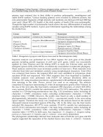
be only 40 metres. Even in the event of a hesitant reaction by the driver, BA
can reduce that stopping distance by about 6 metres. Incidentally, hesitant is
defined as an initial braking reaction producing a deceleration of 7 to 10 m/s,
Fig. 38.30 If the electronic control of the Brake Assist system senses rapid depression
of the brake pedal, indicating an emergency stop, it activates a solenoid valve in the
brake servo unit to apply fully, instead of partially, atmospheric pressure to the right-
hand side of the diaphragm. This provides maximum braking, although still modulated
by the ABS system
1009Servo- and power-operated, and regenerative braking systems
Fig. 38.31. Reactions producing deceleration values of less than 6 m/s or less
are classified as inadequate.
From Fig. 38.30, it can be seen that the brake actuation unit comprises a
fairly conventional brake servo with the addition of a pedal travel sensor, a
solenoid valve which in fact is the air valve, an electronic control unit, and
a brake release switch. So long as the brakes are inactive, induction manifold
depression acts equally on each side of the diaphragm. When the driver
moves the brake pedal, the push rod opens the air valve, applying atmospheric
pressure to the chamber on the right in the illustration. This moves the
diaphragm to the left, until the air valve is closed. Thus, without BAS, the
pressure in the hydraulic brake system is at all times proportional to the
pedal travel.
If the pedal travel sensor recognises a fear-induced excessively rapid
movement of the pedal, the electronic control energises the solenoid in the
centre of the brake servo unit, which opens the air valve fully, instead of
partially: wheel lock is prevented by the ABS system. As soon as the driver
releases the brake pedal, the release switch shown in the illustration breaks
the circuit to the solenoid thus cutting out the boosting effect of the servo,
Fig. 38.32.
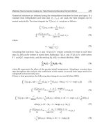
The speed of operation of the brake pedal is not, however, the only signal
upon which the electronic control bases its decision to activate BA. Other
400
300
200
100
0
Pedal force, N
02 4 6
With BAS
Without BAS
Time, sec
Pedal force
Brake pressure
With BAS
Without BAS
Time, sec
100
80
60
40
20
0
0246
Pressure, bar
Fig. 38.32 As soon as the driver releases the brake pedal, a switch breaks the circuit
to the solenoid to cut out the boosting effect of the servo
Fig. 38.31 Comparisons of braking performances with and without Brake Assist
10
8
6
4
2
0
0 0.2 0.4 0.6 0.8 0.
Adequate deceleration
Hesitant driver reaction
Inadequate driver reaction
Time, sec
Deceleration, m/sec
2
1010 The Motor Vehicle
factors include the speed of the vehicle, the state of wear of the brakes,
signals from the electronic control systems for the engine and transmission
management and from other systems such as ABS and, in some installations,
those controlling wheel-spin and vehicle stability.
A major difficulty with such systems, however, is setting the threshold
beyond which an emergency stop is automatically put into effect. This setting
inevitably has to be a compromise that might not be appropriate for some
drivers. For example, consider a nervous driver in an overtaking lane on a
motorway, where traffic situations are liable to change with frightening rapidity.
He might observe a change in the traffic movement ahead that does not call
for emergency braking but, to be sure that he is ready to brake if the situation
does become critical, he rapidly puts his foot on the brake, intending to apply
relatively gentle braking yet, because of his nervousness, he moves
exceptionally quickly. If the control interprets this as an emergency, he could
find himself in a crash stop situation causing the driver of the car behind him
to run into his back end. A similar situation could also arise at slower speeds
in urban traffic, or if the driver suddenly realises that he is exceeding the
speed limit in embarrassing circumstances!
38.17 Stability when steering and braking or
accelerating (ESP)
Modern micro-electronics is revolutionising vehicle control. The advances
that have been made progressively by Mercedes-Benz exemplify the general
trend. It started in 1978 when Automatic Braking Control (ABS) was introduced
on their S-class W 127 Series. Clearly, the sensor that detects wheel lock can
be used also for detecting wheel-spin. So a logical further development was
an Acceleration Skid Control system (ASR), which was announced in 1987.
With this system, if any of the wheels showed a tendency to spin, the engine
torque was automatically reduced and the brake applied to the relevant driven
wheel, or wheels, until stability had been assured. The aim, of course, was
the enhancement of acceleration over the whole speed range. This facility is
especially valuable when there are patches or streaks of ice, or perhaps mud,
on the road.
A further development was the introduction, in 1994, of what Mercedes-
Benz terms Electronic Traction Support (ETS) on their six-cylinder S- and
SL-class and, as an option instead of the Automatic Locking Differential
(ASD), on the C-class. ETS simply brakes any driven wheel, or wheels, that
show signs of inherent spin during acceleration from rest, and then releases
the brake when the speed difference between the driven wheels is reduced to
as small as practicable a level.
The ultimate aim has been the development of an overall stability control
system. This was achieved in 1995 with the introduction, by Mercedes-Benz,
of their Electronic Stability Program (ESP), which is designed to enable the
driver to maintain control in circumstances in which, without it, he would be
unable to do so. Such circumstances might arise, for example, if the driver
were cornering too fast, taking sudden evasive action or, for example, driving
with the wheels on the near side on ice and those on the other side on dry
tarmac.
ESP is a combination of ABS and ASR, in that it stabilises the vehicle by
1011Servo- and power-operated, and regenerative braking systems
braking intervention and torque reduction but, in contrast to these two systems
which are activated only when required, ESP continuously monitors the
situation and therefore is more effective. This greater effectiveness is attributable
to two facts: first, it is coupled, through CAN data bus links, to the electronic
controls for the engine and transmission, so that it can come instantly into
operation in sudden emergencies; and second, its electronic control has many
more inputs from sensors than did its predecessors. These inputs include not
only throttle pedal position and individual wheel speeds, but also direct
readings of transmission ratio and engine torque (instead of relying on pedal
position only), as well as steering angle, yaw, lateral acceleration and brake
pressure. The extra input enable ESP to actually anticipate loss of control,
and to react virtually instantaneously by braking intervention on individual
wheels. Incidentally, a CAN data bus is an electronic circuit that interlinks
the various computer databases for controls such as engine and transmission
management, ABS, and ETS, so that all are continuously updated with the
information they need and therefore are ready instantly to perform their
safety functions in an emergency.
Sited under the back seats of the car are the lateral acceleration and yaw
sensors, the latter being based on aerospace technology. Too high a rate of
yaw warns that the vehicle is about to break away into a skid, while the
lateral acceleration sensor provides information about any tendency to under-
or oversteer. All the inputs are continuously compared with data pre-recorded
on a map of limits of stability relative to steering wheel angles and vehicle
speeds. Should the input values move into a critical region, indicating that
breakaway is imminent, the ESP signals the hydraulic unit to apply the brake
on the relevant wheel or wheels and, if necessary, reduce engine torque. The
selective and precisely metered braking intervention takes place in a fraction
of a second, and the driver is hardly aware of it.
In the event of oversteer, the outer front wheel is braked, while if understeer
is developing, the brakes and throttle control are applied, appropriately, to
reduce the speed of the vehicle, with emphasis on braking on the inner rear
wheel. The whole system is so sophisticated that it even takes into account
how many people are in the car, how much luggage is carried and the depth
of treads of the tyres. More information on this subject, and on a similar
Toyota system, can be found in the chapter on Vehicle Safety, Section 36.16.
38.18 Regenerative braking systems
A simple form of regenerative braking system is often employed on electric
vehicles. It is necessary because the energy storage capacity of a battery of
a weight and size practicable for installation in road vehicles is so small that
one cannot expect to get more than 30 to 40 miles (38 to 64 km) out of it,
even with regeneration of the energy that would otherwise be dissipated in
braking. This type of vehicle has an electric motor and control system such
that, when current is passed through it, it drives the vehicle, but generally
when its control pedal is released, or more unusually during the initial movement
of the brake pedal, the current supply to the motor is cut off and it actually
generates current which is utilised to contribute to recharging the batteries.
Thus, a braking torque is applied to the road wheels, by virtue of the fact that
they are driving a generator.
With the advent of electronically-controlled, constantly variable trans-
1012 The Motor Vehicle
missions it has be come practicable to introduce regenerative braking for
petrol and diesel vehicles. Leyland has been experimenting with such a
system since before 1980, using its CVT with a flywheel for energy storage,
while Volvo had a hydraulic accumulator regenerative system installed on
acceptance trials in a London bus in 1985. Indeed, regenerative braking is
particularly attractive for urban bus operation, since much of the power from
the engine is used for acceleration from bus stops, soon after which it is
dissipated again in braking for the next stop.
Flywheel storage has some disadvantages. First, in the event of an accident
in which excessive shock loading is transmitted to the flywheel, it might
burst and cause casualties. Secondly, it adds significantly to the weight of the
vehicle, thus offsetting some of the gains as regards fuel economy. Thirdly,
it is bulky. Fourthly, it will run down overnight, so the engine has to be
started electrically in the morning.
Most of these disadvantages can, to a major extent, be designed out. For
example, by using fibre-reinforced material for the flywheel it can be made
so that it does not burst into large fragments when ruptured but rather tends
to shear along the fibres and to be retained by them. The weight can be
reduced by the use of a very dense material as a rim on a very light disc, so
that its polar moment of inertia is high relative to its weight. Little can be
done about its bulk, since it must have a flywheel of reasonably large diameter,
though it can be installed with its axis of rotation vertical. To keep it spinning
for a long time it could be housed in a vacuum, but this is hardly practicable;
alternatively, the housing can be filled with a very light gas such as hydrogen
or helium. Even so, to keep it freewheeling for, say, twelve hours is scarcely
a reasonable demand.
With a hydraulic accumulator, on the other hand, overnight storage presents
no problem so that, in the event of, for example, a fire in a bus garage all the
vehicles could be driven out instantly by drawing on the accumulator for
energy, without having to wait for their engines to start and become warm
enough to move off, and without generating any exhaust fumes. Disadvantages
of high pressure hydraulic drive systems, however, include problems of
leakage, and they are inherently noisy under certain conditions, owing to
turbulence and very high local velocities of fluid flow. With low pressures
and velocities, the system becomes unacceptably bulky.
In trials of a Volvo bus in service in Stockholm the use of hydraulic
regeneration has indicated average savings in fuel of between 28 and 30% in
urban operation, though in an extreme case a saving of 35% was made. A
significant proportion of this economy is attributable to the fact that, under
load, the engine can be run virtually continuously at its most economical
speed, the stored energy being used for acceleration and assistance in hill
climbing. With suitable electronic control it might even be possible to stop
the engine during braking and the initial stages of acceleration, though in the
Volvo bus it is kept idling under these conditions.
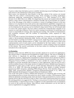
The layout of the control system of what Volvo call their Cumulo system
can be seen in Fig. 38.33 and of the hydro-mechanical system in Fig. 38.34.
Power is derived from a 180 kW diesel engine installed in conjunction with
a fluid flywheel and four-speed gearbox, and with a final drive ratio of
4.87 : 1. A power take-off of the sort used for driving auxiliaries alternately
drives and is driven by, according to the mode in which the vehicle is operating,
a swashplate type hydraulic pump/motor with a 40° Z-shaft and spherical
1013Servo- and power-operated, and regenerative braking systems
A
B
C
D
E
F
G
K
H
J
L
Diesel
engine
Gear
box
Sensors
Actuators
A Throttle
B Brake pedal
C Drive/neutral sensor
D Vehicle speed
E Reservoir contents
F Clutch engagement
G Pump displacement
H Shut-off valve
J Pressure switch
K Relief valve
L Reservoir contents
Fig. 38.33 Diagrammatic layout of the Volvo Cumulo control system, showing the
sensors and actuators
pistons. When this unit is operating as a pump the fluid is delivered from the
reservoir into the hydraulic accumulator. During operation as a motor the
flow of fluid is of course reversed. Pressure for regulation of the angle of the
swashplate on the Z-shaft has to be obtained from a separate pump: if it were
dependent on the pressure in the accumulator, control would be lost if that
pressure became too low.
The electronic control, with its 8-bit microprocessor, is programmed not
only for normal conditions of operation but also for warming up the engine
and charging the accumulators. It also monitors the system continuously at
a frequency of 20 Hz to detect malfunction and check that the safety system
is operational at all times.
The inputs to microprocessor include a potentiometer coupled to the
accelerator pedal for sensing the torque demanded by the driver and another
connected to the brake pedal to sense the deceleration required. A position
indicator senses whether the gearbox is in a drive ratio or neutral and a pulse
pick-up senses the rotational speed of the propeller shaft and thus the vehicle
speed. Another position indicator senses whether the power take-off clutch
is engaged or disengaged. A potentiometer senses the displacement of the
swashplate pump and a position indicator signals the volume of oil in the
hydraulic reservoir, which determines when the engine should be brought
into operation to take up the drive. Finally, there is a pressure sensor on the
accumulator. When the accumulator is full, the incoming oil is diverted to
the reservoir via a pressure relief valve.
Energy stored in the accumulator is locked in overnight by the shut-off
1014 The Motor Vehicle
A
B
A Power take-off gearing B Pump/motor unit C Hydraulic accumulator
Fig. 38.34 Of the three interconnected cylinders in the Cumulo system, the two outer
ones contain nitrogen gas, while the central one also contains gas but is separated by a
free piston from the hydraulic fluid
valve, which is actuated automatically by the electronic control system.
Consequently, the vehicle can be driven out of the garage in the morning,
using stored energy. When it is in the open air the diesel engine can be
started and the bus driven away, still using the hydraulic energy. As the speed
rises to 22 mph (35 km/h), or if the hydraulic pressure drops below a
predetermined level, the engine is automatically accelerated from idling up
to the same speed as the propeller shaft, at which point the engine and
gearbox take over from the hydraulic drive. When the brakes are applied, the
engine reverts to idling and the hydraulic motor to a pumping mode, to
charge up the accumulator. The friction brakes come into operation only if
the control pedal is depressed beyond a spring-loaded detent. Fully charged,
the accumulator stores 0.22 kWh energy, which is adequate for running a
half-laden vehicle at a constant slow speed for about three-quarters of a mile
(1.2 km) or accelerating it, at a constant rate of 1.8 m/s
2
, up to the cut-in
speed of the engine.
The accumulator in Fig. 38.34 comprises three interconnected cylinders,
the outer two containing only compressed nitrogen and the inner one both
gas and hydraulic fluid separated by a free piston fitted with Teflon seals.
When fully discharged, the gas pressure is about 200 bar and, fully charged,
about 350 bar. The system is designed to bring a half-laden city bus to rest
from 31 mph (50 km/h), the difference between this figure and that of 22
mph (35 km/h) for acceleration from rest being accounted for by the rolling
and aerodynamic resistances. While the overall efficiency of the transmission
is about 80 to 85%, that of the hydraulic system is 90 to 96%.
C
1015
Chapter 39
Anti-lock brakes and
traction control
For the sake of simplicity a single wheel will be assumed in the following
description of the fundamental principles of anti-lock systems. Basically, an
anti-lock system comprises a sensor to detect incipient wheel-locking, together
with a system for relieving momentarily the hydraulic pressure to the brakes,
to prevent locking before it actually occurs. As explained in Section 38.11,
when the wheel is slipping only to a small extent, the deceleration will be
low in comparison with the value appertaining to the approach of sliding and
so, when the deceleration exceeds a certain value, the control releases the
brake, the deceleration of which will then fall to a low value and so the
brakes will be reapplied. This release and reapplication of the brakes must
take place in an extremely short time if the system is to work satisfactorily
and, in practice, the cycle will occur up to as high as 15 times per second.
In the early systems the wheel deceleration was measured by purely
mechanical means but in present-day systems electronic circuits are used
because they give much quicker responses and can be controlled more easily.
These circuits are beyond the scope of this book and only an outline of their
action can be attempted.
The deceleration sensor usually consists of a toothed disc attached to the
hub of the wheel, and a pick-up placed near to the periphery of the disc. The
pick-up is essentially a horseshoe magnet with a winding, and the projections
of the disc act as a succession of keepers which bridge the poles of the
magnet thus momentarily causing an increase in the magnetic flux through
the winding and setting up a current in it. The frequency of this current will
depend on the speed of the disc and the rate at which that frequency changes
will be proportional to the deceleration of the disc. This rate can be measured
relatively simply electronically and can then be used to supply a signal for
the control of the brakes. The remainder of the system therefore consists of
valves actuated by the signal and which control the actuation of the brakes.
A sensor may be provided for each wheel to be controlled but sometimes
it is practicable to control the wheels in groups. A common system is to have
a sensor for each of the front wheels and a single sensor with its disc on the
propeller shaft for the two rear wheels together. It will be appreciated that
the incorporation of these anti-lock systems is facilitated by the use of power
1016 The Motor Vehicle
operated brakes, also that they are somewhat expensive and are used therefore
only on the more expensive cars and on certain classes of commercial vehicle.
39.1 Dunlop-Maxaret system
The Dunlop-Maxaret system was developed for application to the driving
wheels of the tractor unit of articulated vehicles in order to prevent the
vehicles from jack-knifing. The system has been most successful in doing
this.
The general layout of the system is shown in Fig. 39.1 and details of the
valves appear in Fig. 39.2. When there is no incipient wheel slide there will
be no signal current from the electronic module to the control valve and so
the port A, Fig. 39.2(a), will be open to atmosphere through the gap at C and
there will be atmospheric pressure on the right-hand sides of the brake actuator
Solenoid
A
C
B
Y
Z
C
X
A
Y
(a) (b) (c)
Fig. 39.2 Dunlop-Maxaret anti-slide system valves
Sensor
Diaphragm
chamber
B
A
Reservoir
Control valve
Brake valve
Sensitivity valve
Balanced
exhaust valve
X
YY
Z
Electronic
module
Fig 39.1 Dunlop-Maxaret anti-slide system
1017Anti-lock brakes and traction control
diaphragms. Hence, when the brake pedal is depressed, air will pass freely
from the service (lower) reservoir to the port Y of the balanced exhaust
valve, Fig. 39.2(b). This pressure will deflect the outer portion of the lower
diaphragm against the force of the spring so that air will pass to the port Z
and thence to the left-hand sides of the brake actuator diaphragms, thereby
applying the brakes. Under poor road conditions depression of the brake
pedal will again pass air to the brake actuators to apply the brakes but if
wheel slide becomes imminent the electric modules will pass current to the
solenoid of the control valve, the gap C will be closed and air will pass from
the anti-skid (upper) reservoir to the right-hand side of the brake actuator
diaphragms and release the brakes.
The pressure air from the control valve will also depress the piston assembly
of the sensitivity valve, Fig. 39.2(c), and this will restrict the passage of air
from the brake pedal valve to the brakes. The pressure that acts on the left-
hand side of the brake actuator diaphragms also acts on the underside of the
balanced exhaust valve and if it exceeds the pressure acting on the upperside
from the port Y the central portion of the diaphragm will be lifted so as to
open the port Z to the atmosphere via the gap opened at C. Thus the valve
equalises the pressures at Y and Z and the brake actuating pressure will at all
times be equal to the pressure determined by the brake pedal valve.
As soon as the anti-skid pressure on the right-hand side of the brake
actuators is released by the cessation of the signal from the electronic module
the brakes will be reapplied. This action will be repeated with a frequency of
several cycles per second as long as the wheel-slide condition continues.
39.2 Lucas-Girling WSP system
The general layout of the Lucas-Girling system, as applied (for the sake of
simplicity) to a single wheel, is shown in Fig. 39.3. It is designed for use
with brakes employing fluid application. Under normal conditions the brake
is applied by the master cylinder in the usual way because the valve A of the
actuator unit of the system is open as shown.
The valve is held open by its spring and by fluid pressure on the left-hand
side of its piston, this pressure being maintained at a constant value by a
pump that is driven by the engine of the vehicle. When a signal is passed by
the electronic module to the solenoid of the control valve, oil from the pump
will pass to the right-hand side of the actuator piston and as the effective area
of this side is greater than that of the left-hand side the piston will move to
the left to close the valve. Because of the decrease in the volume of the stem
of the valve that projects into the chamber B, the pressure in the brake
cylinder will drop and the brake will be released. When the signal to the
control valve ceases the right-hand side of the actuator piston will again be
opened to the atmosphere in the reservoir and the valve will open. The action
will be repeated with a frequency up to some 15 Hz, this frequency being
modified to some extent by auxiliary circuits in the electronic module. When
several wheels are to be controlled each must have its sensor, electronic
module circuit, control valve and actuator but the pump will be common to
all. On the other hand, to reduce cost, some vehicle manufacturers elect to
sense the occurrence of wheelspin per axle instead of per wheel.
1018 The Motor Vehicle
Electronic
module
Reservoir
Pump
Solenoid
Control valve
Sensor
B
A
Brake
cylinder
Master
cylinder
Actuator
Fig. 39.3 Lucas-Girling WSP system
39.3 Ford Escort and Orion anti-lock systems
For the Ford front-wheel-drive Escort and Orion, the Lucas-Girling, low
cost system is used. It has sensors for detecting wheel-lock on only the front
wheels, locking of the rear wheels being initially inhibited by a pressure-
limiting valve. These models have an X-split brake control system, as described
in Section 38.14 so, when operating, the anti-lock system alternatively relieves
and reapplies the pressure to the brake not only on the front wheel that is
about to lock but also on the diagonally opposite rear wheel, Fig. 39.4.
Having two instead of three or four wheel-lock sensors of course is an
economy, but other measures, including the substitution of a mechanical
instead of an electronic sensing and control system and the avoidance of any
need for separate, electric or engine-driven hydraulic pump to supply the
braking pressure also make major contributions to the overall cost reduction.
A flywheel incorporating an overrun device serves as the mechanical sensor.
This is driven from the front wheel by a toothed belt which gears it up to 2.8
times the driveshaft speed. The flywheel, a modulator valve unit and a cam-
actuated reciprocating pump are all in a common housing, Fig. 39.5.
In normal conditions the flywheel accelerates and decelerates with the
road wheel, and the hydraulic modulator valve is functioning as shown in
Fig. 39.6, in which the black areas are those in which the hydraulic pressure
rises as the brakes are applied. In this condition the pump plunger (11) is
held clear of the cam (10) by the plunger spring (12).
If, however, the angular deceleration of the wheel attains a value equivalent
to a 1.2g deceleration of the vehicle, wheel lock is likely to occur and so the
overrun torque generated by the flywheel, due to its inertia, rotates it a few
degrees relative to the hub. This rotation occurs within a ball-and-ramp
mechanism (4), which causes the axial displacement shown in Fig. 39.7. The
consequent axial movement displaces the dump-valve lever (9) about its
pivot, thus opening the dump valve (7).
1019Anti-lock brakes and traction control
Fig. 39.4 Ford Escort and Orion anti-lock system. Note that, as compared
with Fig. 39.5 the control units are upside down
The opening of the dump valve releases the pressure above the de-boost
piston (15) and consequently also relieves that in the pipeline to the brakes.
Since the downwards pressure on the pump plunger (11) has also been released
by the opening of the dump valve, the master cylinder pressure acting on the
piston forces it into contact with the cam (10). Even so, the consequent
reciprocation of the pump plunger cannot generate any hydraulic pressure so
long as the dump valve remains open.
Simultaneously, the de-boost piston, under the influence of the hydraulic
pressure below it, rises to allow the cut-off valve (13) to close, as in Fig.
39.8, thus cutting off the input from the brake master cylinder and relieving
the pressure in the pipelines to the brakes. Therefore, the road wheels accelerate
to the speed of the still decelerating flywheel. At this point the flywheel,
moving back and contracting its ball-and-ramp mechanism, is accelerated at
a rate controlled by the clutch that can be seen in Fig. 39.5. As the lever (9)
is released, the dump valve closes.
This allows the reciprocating pump to increase the pressure above the de-
boost piston and in the pipeline to the brakes. If it again causes the road
wheel to lock, the cycle of events is repeated but if, without wheel lock
occurring, it rises to equal the pressure applied by the driver’s pedal to the
master cylinder the cut-off valve (13) is opened again, the pump disengages
and the master cylinder is reconnected. The effects of the whole sequence of
operations on the input to the brakes and on the wheel spin is illustrated in
Fig. 39.9.
1020 The Motor Vehicle
39.4 Ford Granada, Sierra and Scorpio anti-lock systems
The ABS (Anti-lock Braking System) on the rear-wheel-drive Granada,
Sierra and Scorpio, each of which have a Y-split (Section 37.14) brake
system, is the outcome of co-operation between Ford and the German brake
manufacturers ATE. It has an electronic control, with electro-magnetic sensors
on all four wheels, Fig. 39.10, and an electrically driven pump and hydraulic
accumulator for maintaining sufficient reserve pressure to enable the anti-
lock system to release and reapply the brakes repeatedly at rates of up to
twelve times per second. The electronic control module has two microprocessors
which not only duplicate the processing of the incoming signals but also
monitor each other continuously to check that both are functioning properly.
In the event of a total system failure the brake control reverts to conventional
operation without anti-lock control and an indicator on the dash is illuminated
to warn the driver.
Fig. 39.5 Sectioned control unit for the Ford Escort and Orion
1021Anti-lock brakes and traction control
Frequency signals from the four wheel sensors are translated by the electronic
module first into wheel-speed and acceleration values and then into vehicle
speed and wheelslip. When the slip becomes so great that wheel-lock is
imminent, the control alternatively energises and de-energises the appropriate
hydraulic inlet and outlet solenoid valves in the ABS electro-hydraulic unit,
Fig. 39.11, to relieve and reinstate the pressures in the lines to the brakes.
There are three hydraulic circuits, one for each front wheel and the third for
10
1
11
12
Master
cylinder
13
Brake
7
4
2
6
Fig. 39.6 Positions of the valves in the normal brake operating condition
4
17
9
7
14
15
Brake
Master
cylinder
8
11
Fig. 39.7 Axial displacement of the flywheel displaces the lever to open the dump
valve to the reservoir
Tank
Tank
1 Drive shaft
2 Flywheel
3 Flywheel bearing
4 Ball and ramp
5 Pump outlet valve
6 Flywheel spring
7 Dump valve
8 Pump inlet valve
9 Dump valve lever
10 Cam
11 Pump plunger
12 Pump spring
13 Cut-off valve
14 De-boost spring
15 De-boost piston
16 Cut-off valve spring
17 Dump valve lever pivot
Common key to Figs 39.6–39.8
1022 The Motor Vehicle
2
4
7
Brake
13
16
Master
cylinder
Tank
11
both rear-wheel brakes. The advantage of having a single control over both
rear brakes is good stability when cornering under maximum braking and a
Fig. 39.8 Closure of the dump valve allows the pump to build up the brake pressure
again
Braked wheel
speed
Braked wheel
decelerating
Brake
pressure
Time
Flywheel lost motion
Dump valve opens
Vehicle speed
Dump valve reduces
brake pressure
Pump re-applies
brakes
Accelerating shaft
picks up flywheel
Flywheel accelerated
by clutch
Flywheel over runs
on clutch
1
2
3
4
5
6
7
8
Wheel
speed
Flywheel regains
braked wheel speed
Dump valve opens
Fig. 39.9 Brake pressure and wheel speed plotted against time throughout the
sequence of operations of the Lucas Girling anti-lock brake system
1023Anti-lock brakes and traction control
reduction of oversteer by reducing the brake torque on the most heavily
loaded rear wheel. At the same time, the reduction in the overall braking of
the vehicle is minimal because of the effect of the apportioning valve in
limiting the contribution by the rear wheels to only a fraction of the total.
During operation without anti-lock the front brakes are actuated by the
master cylinder with assistance from its integral hydraulic servo, while the
rear ones are actuated by pressure from the hydraulic accumulator. This
accumulator is maintained at 140 to 180 bar by the electric pump. The
control valve linked to the piston rod of the tandem master cylinder, Fig.
39.11, maintains a constant relationship between the hydraulic output pressure
from the servo and the input force applied by the brake pedal to the master
cylinder.
39.5 Traction control
For the similar Ford models that have also four-wheel-drive based on the use
of viscous couplings, Section 31.10, a further development of the ABS electronic
control system takes into account also the interactions between the four
wheels, through the viscous couplings, under varying engine torques. In
other words, what is termed traction control is incorporated. This entails
automatic alternate application and release of the brake on either driven
wheel as soon as the microprocessors detect that it is about to spin. Obviously,
therefore, the electronic control module has to differentiate between wheel-
lock and wheelspin. With full traction control, as soon as the driving wheel
on one side spins the brake is applied on that side, but if the wheel on the
other side then spins, the electronic control closes the throttle or reduces the
Fig. 39.10 Layout of the anti-lock brake system of the Ford Sierra with (above left)
the electro-magnetic pick-up to a larger scale
—— Hydraulic brake circuit Sensor and warning lamp circuits Control circuit
1024 The Motor Vehicle
A
K
J
H
G
F
E
D
C
B
G
A Hydraulic accumulator
B Control valve
C Hydraulic booster
D ABS master cylinder
E High pressure pump
F Electric moter
G ABS valve block with six solenoid valves
H Pressure warning switch
J Main valve
K Hydraulic fluid reservoir
Fig. 39.11 Two views of the Teves combined master cylinder and ABS unit. The control valve equalises booster and master cylinder
output pressures
1025Anti-lock brakes and traction control
rate of fuel injection to reduce the torque output from the engine. All these
control operations are effected within milliseconds.
For starting from rest the traction control system must be much more
sensitive to drive slip than for either simple acceleration from one speed to
another or deceleration in anti-lock systems. Additionally, it must also
differentiate between wheel-speed differential due to the vehicle’s being
simultaneously driven round a corner. The electronic control unit is virtually
identical to that for the Mk IV system, Fig. 39.14, which is described in the
last two paragraphs of Section 39.6
39.6 Teves Mk IV ABS and traction control
In Fig. 39.12 the Teves Mk II system, for the Ford two- and four-wheel-drive
cars, Sections 39.4 and 39.5, is compared diagrammatically with the Mk IV
system. Cost reduction, to render the equipment suitable also for less upmarket
cars, was the primary incentive for the Mk IV development. The principal
economies were the substitution of a vacuum for a hydraulic servo, or booster,
and the use of a pump of higher output, at extra cost, to obviate the need for
an accumulator. With the abandonment of the hydraulic booster J containing
the control valve, equalisation of the output pressure from the ABS pump to
the brakes with that from the master cylinder has had to be effected by means
of valve A incorporated in the centre of the piston of the master cylinder.
The Mk IV system, too, has acceleration/deceleration sensors on each
rear wheel, and the brake pressure to both rear wheels is reduced or increased,
as appropriate, to the level necessary to control the locking, or spinning,
wheel. All-wheel control gives the sensitivity needed for traction control,
and greatly reduces the possibility of rear-end instability in all modes. The
A Master cylinder
B Fluid level sensor
C Reservoir
D
1
Solenoid valve (inlet)
D
2
Solenoid valve (outlet)
E Disc brake
F Non-return valve
G Electrically driven pump
H Hydraulic accumulator
J Control valve in the hydraulic booster
K Pressure switch
C
B
FG
A
D
1
D
2
E
B
M
M
H
J
D
1
D
2
K
E
Fig. 39.12 Comparison between the Teves Mk II (right) and Mk IV (left) anti-lock
brake systems. The hydraulic circuit to only one brake is shown since the others are
identical to it
1026 The Motor Vehicle
electric pump is switched on by the electronic control system only when it
is required to build up the brake pressure in the anti-lock or anti-spin modes
(ABS or traction control operation), so little energy is consumed.
From Fig. 39.13 it can be seen that the general arrangement of the Mk IV
system is similar to that of the Mk II except that, in the Mk IV, the master
cylinder and reservoir together have become a separate unit. Also, the system
illustrated is designed for an X-split braking system, as compared with the Y-
split of the Ford two-wheel drive layout.
If a wheel tends to lock, the electronic controller closes the solenoid-
actuated hydaulic inlet valve to its brake and opens an outlet valve in the line
back to the reservoir. Simultaneously, it switches on the electric motor. Since
the inlet valve to the brake circuit is closed, the fluid delivered from the
pump can only force the piston in the master cylinder back until the valve in
the centre of its piston, Fig. 39.12, opens to release all fluid in excess of that
required for ABS operation back to the reservoir. This ensures that the pressure
generated by the pump cannot exceed that induced by the driver through his
brake control pedal, and that the driver does not lose the feedback from (the
feel of) his brake control.
As the unlocked wheel accelerates back to the appropriate speed, the
outlet valve D
2
in its brake circuit closes and the inlet valve D
1
opens, so the
pump brings the brake application pressure back up to the level dictated by
the force exerted on the pedal. If the wheel again starts to lock, the sequence
is repeated. Incidentally, the non-return valves shown in Fig. 39.12 prevent
fluid from flowing back to the reservoir under pressure exerted by either the
pump, hydraulic accumulator or master cylinder when the brakes are applied.
For safety, the electronic control circuit, Fig. 39.14, is duplicated. There
are two identical microprocessors, each with its own comparator. The
A Vacuum servo
B Electronic controller
C Rear brake sensors
F
A
B
E
D
C
D Front brake sensors
E Hydraulic module
F Tandem master cylinder
Fig. 39.13 Schematic layout of Teves ABS IV anti-lock brake system
1027Anti-lock brakes and traction control
comparators check both the internal and external signals from the wheel-
speed sensors and to the valves respectively. If they do not correspond the
defective circuit is switched off and a warning lamp illuminated on the dash.
There is also a continuous monitoring system for checking the performance
of the sensors, connections, solenoid valves and hydraulics. In the event of
a failure, the brake system reverts to operation without ABS, and again the
driver is warned by a lamp on the dash.
This system can be expanded to include traction control. The extra cost is
small because the same sensors and valves are used, though some extra
valves do have to be introduced. Some expansion of the hardware and software
in the electronic controller is necessary, too, since a traction control system
may have to apply, instead of release, a brake to prevent wheelspin and,
moreover, it has to prevent the wheels from spinning at any vehicle speed. It
is also required to intervene in the engine control, as described in Section
39.5. An advantage of the X-split hydraulic system shown in Fig. 39.13 is
that the driven wheels can be controlled individually to provide optimum
traction, instead of perhaps having to reduce the traction on both wheels to
that obtainable from the more lightly loaded wheel when cornering.
39.7 Advanced anti-lock braking systems
At this point it is necessary to examine, in greater detail than earlier in this
chapter, all the phenomena associated with braking, skidding and steering.
Indeed, the design of an automatic braking system (ABS) entails much more
than simply alternately cutting off and re-establishing the hydraulic pressure
supply to the brakes. For instance, the system must not operate at a frequency
that could cause resonant vibrations in the drive line. For the same reason,
precipitous pressure drops and rises have to be avoided.
As indicated previously in this chapter, the peripheral accelerations of the
Microprocessor 1
External signals
Logic-
block
Internal
signals
Sensors
Comparator 1
Comparator
2
Internal
signals
Logic-
block
Microprocessor
External signals
Valves
+ Battery
Off
Off
Fig. 39.14 The Teves MK IV electronic control system is duplicated
1028 The Motor Vehicle
wheels serve as indicators of impending onset of wheel locking. In this
context, there is a difference between the dynamic characteristics of driven
and undriven wheels. For instance, if a gear is engaged, especially 1st or 2nd,
while the vehicle is being braked, the effective mass moment of inertia of the
rotating driven wheels will be perhaps as much as four times that of the
undriven wheels. This affects the rate of response of the wheels to brake
torque variations during ABS operation. Indeed, if this were not taken into
consideration, the deceleration of the driven wheels could rise well into what
is termed the unstable braking range before the ABS system intervenes.
39.8 Braking force coefficient and slip factor
If the brakes are fully applied, the retarding force rises rapidly to a maximum
and then, if the wheels lock and the vehicle therefore slides, falls off initially
progressively but almost immediately followed by a rapid drop to a low level
although not to zero. During sliding, the coefficient of friction between the
tyre and road is therefore significantly lower than that when the wheel is
rolling. Where a film of water covers the road, aquaplaning can occur, Section
36.5, resulting in loss of all braking and steering control.
The braking force coefficient is defined as:
µ
hf
= F
n
/F
r
where F
n
= the normal, or vertical, and F
r
is the horizontal friction force
between road and tyre. The latter coefficient ranges from about 0.05–0.1 on
ice, to 0.2–0.65 in wet conditions, to 0.8–1.0 on dry road surfaces.
As the hydraulic pressure applied to a brake increases, the braking torque
and therefore the drag force at the periphery of the tyre rises at a steady rate.
So long as the brakes are on, however, there is always a degree of slip
between the tyre and the road, owing to distortion of the rubber in the
regions through which the braking forces are transmitted to the road. It, of
course, increases with increasing brake pressure. This state of affairs exists
throughout what is termed the stable range of braking.
When the drag force exceeds the limit set by the coefficient of friction
between the tyre and road, wheel lock will occur, so the wheel will be sliding
instead of rolling along the road. Also, the braking force coefficient will fall
rapidly, by at least 10–20% and then remain constant regardless of any
increase in brake pressure. This is termed the unstable range.
Without some wheel slip, neither braking nor acceleration can occur. A
similar situation arises with steering: without a steering slip angle, there can
be no side force and therefore no steering control. Consequently, if the
wheels lock, steering control will be largely lost because the rubber has
deformed to, or close to, its limit under the longitudinal braking load, leaving
little or no spare capacity for lateral deformation. If the brakes are applied
while the vehicle is cornering, the total friction and rubber deformation
available has to be apportioned between the braking and steering forces: the
curves in Fig. 39.15 give some idea of the proportions. Clearly, the predominant
force is that due to the inertia of the vehicle, which tends to cause it to
continue in a straight line, in conformity with Newton’s first law.
The braking slip factor is defined as:
λ
= (V
f
– V
u
)/V
f
1029Anti-lock brakes and traction control
where V
f
= vehicle speed and V
u
= the velocity at the periphery of the tyre.
From this equation, it can be seen that slip occurs as soon as the wheel speed
falls below that which corresponds to that of the vehicle, in other words
when
λ
= 1. Both slip (or incipient wheel lock) and actual wheel lock (sliding)
are detectable by wheel-speed sensors.
39.9 Bosch anti-lock (ABS) systems
Bosch produce a range of anti-lock brake systems including ABS 2S, ABS
5.0, ABS 5.3 and the ABS/Automatic Brake force Differential lock, ABS/
ABD 5. These are described and illustrated in detail in the Bosch Publication
No.1 987 722 193 ‘Brake Systems’, 2nd edition, June 1995 and also, although
in lesser detail, in the Bosch Automotive Handbook, 2nd edition, which is
available in the English language. What follows here is largely a summary of
the basic principles, and some details of the ABS 2S system.
The heart of this system is the hydraulic modulator which, interposed
between the brake master cylinder and the wheel-brake cylinders, implements
the commands from the ECU. These commands are executed by means of
solenoid-actuated valves which regulate the pressures in the wheel-brake
cylinders. The hydraulic modulator contains, in addition to the solenoid-
actuated valves, an electric motor-driven fluid-return pump, and one hydraulic
accumulator chamber for each wheel-brake cylinder. Ideally, the modulator
is installed in the engine compartment, to keep the pipe lines to both the
master cylinder and the wheel-brake cylinders as short as possible.
Four-channel versions of the modulator are available for vehicles in which
1.0
0.8
0.6
0.4
0.2
0
Braking and lateral force coefficients
0 20406080100
Braking force
coefficient
Lateral force
coefficient
10°
2°
Brake slip, per cent
10°
2°
Slip
angle
Fig. 39.15 Note that the braking force coefficient remains high as brake, or wheel,
slip increases, while the lateral force coefficient falls off rapidly
1030 The Motor Vehicle
the brake pressure to each of the four wheels is regulated by a separate
solenoid valve. For vehicles in which the brakes on two front wheels are
regulated individually and those on the back axle by a single solenoid valve
there are 3-channel versions. As can be seen from Fig. 39.16, each valve has
two ports and can be moved by the solenoid to any of three positions, according
to whether the pressure to the wheel cylinders is to be increased, held or
reduced. The cam-actuated plunger type return pump transmits back to the
brake master cylinder the fluid released cyclically from the brake actuation
Wheel
speed
sensor
ECU
Wheel brake cylinder
Fluid return pump
Brake
master
cylinder
ECU
Accumulator
Solenoid
Armature
Pump
motor
ECU
Fig. 39.16 The three phases of brake pressure modulation. Top, pressure build-up:
solenoid armature in its lowest position, opening the upper and closing the lower
solenoid valve. Middle, pressure hold: armature in its mid-position, closing both
solenoid valves. Bottom, pressure reduction: solenoid armature in its uppermost
position, opening the lower solenoid valve. This releases pressure from the brake
actuation cylinder into the pressure accumulator, the pison of which moves to the
right. At the same time, the motor rotates the eccentric, pushing the piston of the
return pump to the left, forcing fluid back past the now open ball valve to the brake
master cylinder.