The Motor Vehicle 2010 Part 14 pot
Bạn đang xem bản rút gọn của tài liệu. Xem và tải ngay bản đầy đủ của tài liệu tại đây (775.51 KB, 70 trang )
936 The Motor Vehicle
road. This not only increases the speed of onset of aquaplaning, but also
helps to maintain a high coefficient of friction between tyre and road.
Incidentally, a useful rule of thumb for estimating aquaplaning speeds for
tyres without treads is:
Aquaplaning speed = 9 × √tyre pressure
It is based on experimental data and the fact that recommended tyre pressures
are a function of, among other things, the load on the tyre and the area of its
contact patch with the road.
Aquaplaning occurs when the film of water on the road is driven by the
forward rolling motion of the wheels into the wedge-shaped-gap between the
tyre and the leading edge of its contact patch with the road. At the critical
aquaplaning speed, the pressure in this wedge of water has risen to the point
at which it is high enough to support the vehicle. Therefore, the tyres then
ride up on to the film of water, which, of course, has a coefficient of friction
even lower than that of ice, so the car is floating and will respond to neither
steering nor braking forces.
An important aspect of design for active safety is the minimisation of
driver stress and fatigue. Another is provision for warning the driver of
danger as early as possible before the situation becomes critical. To this end,
good all round visibility and efficient lighting at night are, for instance, two
of the measures that can be taken. Others include the installation of devices
such as electronic detection systems for warning the driver that he is becoming
drowsy: some of these depend on the monitoring of eyelid movements and
others of pulse and steering wheel movements. Thirdly, the design should be
such that, should the car become involved in an accident, its occupants will
be, so far as practicable, protected from injury due to collapse of the structure.
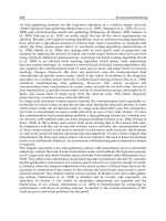
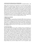
Fig. 36.10 The HITS (Head Impact Test System) rig used by MIRA for assessing the
occupant-friendliness of interior components and trim
937Vehicle safety
36.6 Structural safety and air bags
Since it is neither practicable nor desirable to build vehicles as strong as
tanks, their basic structures must be designed to collapse in a controlled
manner in an accident. A prime consideration is to prevent the steering wheel
from being thrust back and crushing or penetrating the driver’s chest or neck
or, perhaps, even breaking his jaw. Among the measures originally adopted
were the inclusion of telescopic or concertina type collapsible elements in
t
he steering column. In some early instances, the lower end of the steering
column tube was coarsely perforated, so that it would collapse when
subjected to heavy axial loading.
Another of these measures was the incorporation of two universal joints,
one at the lower end of a shortened steering column shaft and the other on
the steering box, the section between them being set at an angle relative to
the axis of the steering column. In the event of a front end impact, the section
between the two universal joints would displace laterally instead of pushing
the upper part of the column back towards the driver.
Subsequently, two further changes were made. One was to increase the
area of the hub of the wheel, to reduce the intensity of loading locally on the
chest. The other was to reduce the stiffness of the rim of the wheel, so that,
if the driver was thrown forward on to it, it yielded rather than severely
damaging his rib cage.
Later, gas-inflated bags were installed in the steering wheel hub, Fig.
36.11. These are supplementary safety devices, as they are effective only in
conjunction with correctly adjusted seat belts. They can be inflated by air
but, to obtain rapid deployment, inflation using chemicals producing nitrogen
or other gases are more commonly used. Correctly tensioning the belt is
important, otherwise it will fail to guide the driver in a manner such that his
face comes down on to the air bag instead of slithering over it and striking
hard objects beyond. In the USA, failure of drivers to fasten seat belts has
been the cause of serious injuries, which has led, unjustifiably, to doubts
being expressed regarding the effectiveness of air bags.
For the protection of front seat passengers, air bags are installed behind a
panel in the dash fascia, and side air bags may be embodied in the seat
squabs. An advantage of the latter site is that it moves with the seat when its
position is adjusted, so the bag can be smaller than if it were stowed, for
example, in the door. Moreover, in the door, it could be more vulnerable to
impact damage. Mercedes has developed what they term window bags, 2 m
long, for the protection of the heads of all the passengers, which otherwise
could be injured either by hitting the side window or by intrusion. These are
stowed in the sides of the roof, and deploy in 25 ms. Bags suspended from
the cant rail and extending the full length for protecting the passengers in
both the front to the rear seats are sometimes called curtain bags.
In general, because the occupants’ heads start further away from the bags
than do their shoulders, side bags at or near shoulder height, for protection
against side impacts, should open earlier than those for either window bags
or those for frontal impacts. To meet this requirement, Toyota have developed
a system in which pellets of a chemical that generates mostly argon gas are
used for inflation. The sensors are mounted low in the centre pillars and the
air bags are stowed in the front seat squabs.
938 The Motor Vehicle
Padded lid
Bag
Casing
Inflator
Dash
Steering
wheel pad
Enhancer
Squib
Bag
Gas
generant
Screen
Inflator
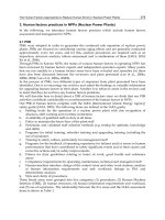
Fig. 36.11 Two Toyota gas bag installations: left, in the dash for the front seat passenger
and, right, in the steering wheel hub, for the driver. In both instances, an electrically
fired squib generates the heat to fire the pellets which generate the gas. As the bags
inflate, they push away the padded trim panels beneath which they are housed
Since the primary impact may be over within 10 ms, all the bags have to
deploy within 20–30 ms. To obtain rapid deployment, most manufacturers
employ pellets of sodium azide which, when heated, produce large quantities
of nitrogen to inflate the bags. Sodium azide is a salt of hydroazic acid
(N
3
H
3
). Initially, air bag deployment was mostly triggered by deceleration
force acting on some very simple form of mechanism, such as a ball in a
tube, mounted adjacent to, or within, the steering wheel hub. Subsequently,
electrically fired gas generators have been triggered by computers in response
to its receipt of appropriate deceleration signals. The deceleration sensors
are usually mounted on a front transverse member of the vehicle structure.
An advantage of this system is that the whole sub-assembly, including the
gas generator, can be housed compactly within the steering wheel hub assembly,
and the deceleration sensor can be placed in any position where it will be
most effective, Figs 36.11 and 36.12.
Perforations in all bags allow the gas to leak out at a rate that increases
with internal pressure, thus modifying their spring rates so that the occupants’
heads do not rebound violently. This at least reduces, and hopefully even
completely obviates, the possibility of spinal whiplash damage. Moreover,
the deflation and collapse of the bag, within a few ms after inflation, leaves
the steering wheel relatively clear of obstruction so that the driver will have
a better chance of regaining control after the impact. In the event of a multiple
collision, the air bags are, of course, effective in only the first impact.
Steering
wheel
939Vehicle safety
36.7 Passenger compartment integrity
The compartment that houses the driver and passengers should remain intact
after an accident. Four measures are necessary: one is to incorporate crush
zones at the each end of the car; the second is to stiffen the door and its
immediate surroundings so that, in the event of a side impact, it will not be
penetrated or deflected violently inwards and strike the occupants; third, the
door trim must be soft or side air bags must be installed so that, if the
occupants are flung against it by the lateral acceleration, they will not be
seriously injured; and fourth, the door frame and not only its joins but also
those between the pillars and cant rail must be strong and stiff enough to
react elastically to absorb the shock loading.
Basically, the occupants must be housed in what amounts to a strong cage,
which will protect them also if the car rolls over. This generally entails the
use of substantial fillets, and perhaps the fitting of reinforcement plates, at
the joints between the pillars and the cant rails and sills. With the current
need to reduce overall weight, the use of thin gauge high strength ductile
steel, instead of the traditional thicker gauge high ductility material for structural
members and some body panels can help to improve both crushability and
integrity of structures.
It is important to design so that the loads due to an impact (whether front,
rear or side) are, so far as practicable, spread uniformly throughout the
whole structure and that the proportions of all the principal members of the
cage containing the occupants are adequate to react those loads elastically.
Diagonal and transverse members may have to be incorporated under the
Direction
of impact
Spring
Igniter
Driver’s seat
bag
Nitrogen
Firing pin
InflatorMechanical sensor
Air bag for driver
Airbag sensor assembly
Power
Igniter
Inflator
Inflator
N
N
Igniter
Direction
of impact
Sensor at
front of
vehicle
ECU
(Sensor at base
of door pillar)
Weight
Front passenger’s air bag
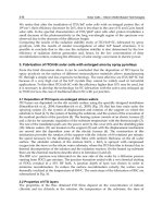
Fig. 36.12 Top, mechanically actuated bag firing mechanism: bottom, electrically
actuated alternative. The latter has the advantages of greater compactness of the parts
that may have to be accommodated in the steering wheel hub and the sensors and
electronic control unit can be sited in the most appropriate positions
940 The Motor Vehicle
floor and, possibly, in the roof to transfer some of the loads from one side to
the other especially, although not solely, for catering for side or offset frontal
impacts.
If the shock to the occupants is to be reduced significantly, a considerable
proportion of the total kinetic energy of the moving vehicle must be absorbed
by the crush zone as it collapses. At the front, the space between the grille
and engine is inadequate for absorbing that energy, except in very minor
collisions. Consequently, in the more severe accidents the engine will be
pushed back, and it is important to prevent it from thrusting the dash and toe
board back until they strike the occupants and possibly trap them in their
seats. Consequently, the engine is generally mounted in a manner such that
it will be deflected downwards and slide under the toe board. In particular,
if the engine is on a sub-frame, the attachment of the longitudinal members
of that frame to the toe board and front floor can be designed to shear, to
enable the whole installation to slide back under the floor. Even so, the dash
and toe board structure must still be stiff enough to prevent significant engine
intrusion into the saloon. At the rear, there is more space for a crush zone, but
the fuel tank must not be ruptured, which is the reason for the modern trend
towards installing fuel tanks much further forward than hitherto.
Ideally, the structure should collapse progressively at a constant rate, as if
it were a sprung buffer, Fig. 36.13. One design method that has been successful
is to bow the longitudinal members so that they either spread outwards or
collapse progressively inwards when heavily loaded in compression. Another
is to incorporate vertical swaged grooves in the side walls of straight members
so that they collapse in a controlled fashion. Ideally, the swages would be
distributed alternately, along each side, over the length of the longitudinal
members of the frame or sub-frame. However, the zig-zag, or concertina
type of collapse thus aimed at is extremely difficult to achieve in practice.
Once the first kink has formed, usually at the foremost swage, the member
is already bowed and therefore is more likely to continue to do so than to
concertina. One manufacturer has notched the corners of the rectangular
section longitudinal members to initiate progressive collapse. Each notch
Swages
Fig. 36.13 Diagrammatic representation of front longitudinal frame member carrying
the suspension and engine. The lengths of the swages, in each set of four (in the top,
bottom and two sides of the frame), become progressively smaller, from the foremost
to the rearmost, so that the frame will offer progressively increasing resistance to
collapse in a frontal impact. The lower diagram shows it only partially collapsed
941Vehicle safety
extends from the corner only a very short distance down one face and a long
distance across the other face. However, one should be wary of introducing
notches in such structural members subject to fatigue loading, since cracks
are liable to be generated by and spread from the stress concentrations thus
induced.
It is preferable to encourage simple bowing by siting all the swages along
either the outer or the inner face rather than the top and bottom of each member,
to cause both to bow respectively either inwards or outwards. If both bow
outwards, the restriction imposed by the body panelling attached to them
will help considerably in providing a progressive reaction to the crushing
force, If they bow inwards, they are similarly restricted, but perhaps by the
presence of the engine between them. Inward bowing, however, tends to absorb
more energy per unit of length of collapse. This might or might not be what
is desired, hence crash testing is essential for proving designs.
An aspect that should not be overlooked is that swaging the sides of the
longitudinal members will reduce their stiffness for reacting to side loads.
This need not be serious if the ends of the vertical swages terminate short of
the junction with the top and bottom plates, each of which will then become,
in effect, a separate U-section member. The ends of the arms of each U
terminate where the swages begin, Fig. 36.14. Incidentally, box section
longitudinal members can be welded fabrications. Alternatively, they could
be square section tubes, the swages being produced by hydroforming, using
internal hydraulic pressure to expand the tube into a mould.
36.8 The problem of the small car
In an impact with a large car, a small car is inevitably at a disadvantage
because the inertia of the former is greater than that of the small car. Moreover,
the provision of a crush zone of adequate length at both the front and back
of the small vehicle is, of course, much more difficult. For this reason, the
principle of designing for the engine so that, when thrust backwards, it slides
B
C
AD
EH
FG
16t 16t
AD
EH
FG
BC
Fig. 36.14 Sections through two box section frame side members, one tubular and the
other fabricated. Although the swages in their sides weaken them so far as taking side
loads is concerned, these loads can be taken mainly in the sections ABCD and EFGH.
A useful rule of thumb is that a length equal to 16 multiplied by the thickness of the
metal represents the maximum length that is stable on each side of each angle under
compression, the measurement being taken from the inner face in each corner or, for
the fabricated section, the centres of the bends
942 The Motor Vehicle
down beneath the toe board and floor is the only practicable course.
Furthermore, maximum use should be made of transverse members to distribute
the loads appropriately between all the longitudinal members, including the
body panelling, in a manner such that they are all equally stressed, as in Fig.
36.15.
An interesting feature in this illustration is the pair of gusset struts, one
each side, between the front transverse member and each longitudinal side
member. If an impact occurs as indicated by either of the two thick arrows,
the corner affected by the impact will be pushed back. The gusset strut will
stabilise the front end of the side member so that, assuming it is designed to
collapse concertina fashion, it will not bow. Moreover, the transverse member
will tend to pivot about the opposite corner, which will be stiffened by the
gusset strut. It therefore will offer more resistance to the pivoting movement,
and therefore a larger share of the impact loading will be transferred to that
side than if there were no gusset member there. At the rear, the design is such
that the spare wheel will help to take some of the loading from a rear end
impact and transfer it to the main structure.
At the rear, the main requirement again is to utilise transverse members to
the best advantage. Also important is a robust C-pillar and a good supporting
structure for the rear axle. Double skinning the rear quarter panels can
enormously strengthen that part of the structure, although this does raise
problems as regards repair to minor damage. In general, the overall strength
and integrity of the occupant cage may need to be higher than that of a car
with long crush zones front and rear.
Front
B
A
Fig. 36.15 Below: plan view of a Toyota frame designed to spread the loads imposed
by front and rear end impacts uniformly throughout the structure. The combination of
the front transverse member and the diagonal members, A and B, one on each side,
triangulate the front end of the frame to constrain it to collapse concertina fashion, as
shown in Fig. 36.13. Scrap view above: elevation of a different frame, showing how
the loads are distributed as viewed in a vertical plane. The triangulation struts shown
in this example are fitted in the door frames
943Vehicle safety
36.9 Side impacts
As regards side impacts, there is not enough space within doors to serve as
a crush zone, so the emphasis is on the use of transverse members between
the sills and cant rails to share the loading between the structural elements on
both sides of the vehicle. Within the doors themselves, horizontal beams the
ends of which are securely fixed to the front and rear frame members of each
door are widely used. However, it is difficult to make them stiff enough to
help much unless the frame and especially its waist and bottom rails are very
stiff, so that vertical or diagonal beams can be fixed to them to support the
centre of the horizontal ones. The longer the door, the more intractable is the
problem. Of particular importance is that the B-pillar be strong enough to
prevent it and, with it, both doors from being pushed inwards in a side
impact situation.
In general, if the central portion of the outer panel of the door is thrust
inwards, it will tend to pull not only its front and rear edges, but also the
waist and bottom rails towards each other. Consequently, all these members
must be adequately stiff. Another measure that has been adopted, for example
by Volvo, is to fill the space between the outer and inner panels of the door
with a plastics honeycomb. If the hexagonal elements of the honeycomb are
fairly thick, the filling as a whole will offer significant resistance to penetration.
Moreover, it also transfers some of the loading radially outwards to the door
frame members and thus further reduces the tendency towards penetration of
the door. It would appear, however, that structural stiffening alone will not be
sufficient to satisfy future legislation, so the installation of side air bags to
supplement the door stiffening measures will probably be inescapable. Arm
rests which could be forced against the vulnerable areas of the lower ribs of
the occupants, should not be installed.
36.10 Smart air bags
Some early work with air bags revealed shortcomings, but these have been
overcome. First, the occupants of the car must be accommodated in fully
supportive seats, with their seat belts fastened. Second, the bags in front of
the driver and passengers must not deploy in any situation other than a
serious frontal impact. Third, because the impact in a crash is usually over in
about a tenth of a second, the deployment of the air bags must be accurately
timed. Deployed too soon, they might strike the occupants’ faces and cause
the driver to lose control earlier than he might otherwise have done and, if
too late, they may be ineffective.
Research to overcome these problems has demonstrated that first the precise
shape of the impact acceleration pulse must be determined. This is a function
of the crush characteristics of the front end of the car. Then the characteristic
of the performance characteristics of the bags is ascertained, so that the
deployment and collapse can be synchronised with that of the pulse. Gas-
inflated bags deploy in about 20–30 ms, but they have perforations in them
so that they subsequently deflate to enable the driver to maintain control
after the impact. In any case, if they did not deflate, the heads of the occupants
might bounce back from them, possibly causing neck injury.
An outcome of this research is the development of computerised controls
for regulating not only the deployment, but also the tensioning of the seat
944 The Motor Vehicle
belts. These are the smart air bags referred to in Table 36.1. Signals transmitted
to the computer include seat belt tension, rapidity of brake application, and
the deceleration detected by a sensor mounted on a front transverse member
of the structure of the vehicle.
If the belts are too loose, the occupants are accelerated forwards before
being suddenly restrained by them, which can cause injury. Incidentally, the
acceleration sensor for side air bag control is generally mounted at the base
of the door pillar. Testing is now carried out initially using computer programs,
which are followed by full-scale crash tests both to prove the validity of the
computer modelling and to enable any fine tuning necessary to be done.
Smart air bags are still under development, so further sophistication can
be expected. A recent advance has been the provision of sensors and a
control system that will inhibit deployment of bags in front of empty seats.
This will reduce costs for the owner, since only those for the occupied seats
will need to be reinstated. A further refinement that has been proposed is
automatic assessment of the size and weight of each occupant and his or her
belt restraint status, and setting the deployment characteristics accordingly.
Yet another factor that can be brought into the equation is the direction and
severity of the crash.
Compartmented air bags have been produced that could be selectively
inflated, according to the severity and direction of the impact, and perhaps
the weight of the occupant of the seat, or whether a child seat has been fitted.
Following instantaneous assessment of the weight of the occupant relative to
vehicle speed or the severity of the impact and seat belt status, such a system
might be able to inhibit deployment if it is unnecessary.
TRW Automotive has developed what they call a heated gas inflator (HGI),
in the form of a vessel containing a weak mixture of hydrogen and air at a
pressure of 175 to 310 bar, as a substitute for explosive pellet type inflators. This
device would be difficult to accommodate in a steering wheel hub, but it
would be suitable for passenger and side air bags. Two or more such devices
might be used for multiple rates of deployment or for compartmented air bags.
Further in the future, we might see radar-based systems for gauging the
closing speed of the car with the vehicle ahead, or any other object with
which the car might be approaching, and setting the air bag control system
appropriately. This could entail also the fitting of an acceleration sensor in
the crush zone.
Current provisions for adjustment of the driver’s seat and steering wheel
could, if he had short legs and a long body, place him too close to the
steering wheel for safety in the event of air bag deployment. It therefore
could become desirable to mount the pedals on a base plate that could be
moved horizontally to adjust its position relative to the seat. This, together
with the usual seat adjustment facility, would give the driver the means of
positioning himself optimally in the horizontal sense relative to his steering
wheel and other controls. Vertical adjustment of either the steering wheel or
seat might also be desirable, however.
36.11 Seat belts
Ideally everyone would have a safety harness of the two shoulder strap (four
point) type, worn by aircraft pilots and rally drivers. However, this is commonly
regarded as too restrictive to be acceptable by the motoring public. It is also
945Vehicle safety
more costly than the adjustable combined lap and single shoulder strap (three
point) type harness. The latter type is satisfactory if the lap belt fits snugly
round the pelvis, the upper anchorage for the shoulder strap is low enough to
prevent strangulation or damage to the neck of the person it is supposed to
protect, the whole harness is a reasonably close fit around the body, and the
occupant can instantly release himself from it in the event of, for example,
a fire hazard.
To obtain a snug fit without discomfort to the wearer, and so that the strap
automatically winds back on to its reel when not in use, the harness reel is,
of course, spring loaded. A further refinement is an acceleration sensor,
either mechanical or electronic which, in the event of an accident, triggers a
ratchet to lock the belt and thus hold the occupant firmly and snugly in his
seat. If this trigger mechanism is too sensitive, the belt may lock unnecessarily
and cause discomfort to the occupant: on the other hand, if not sensitive
enough, it may fail the occupant in a real emergency.
The shape of the seat bucket must be such as to prevent him from sliding
down through the lap belt, sometimes termed submarining, and the combined
effects of both the lap and shoulder straps should restrain him from being
shot either forwards or upwards out of the seat. Another requirement is that
when the belt is retracted, the buckles must be in a position such that, when
the occupant is seated, he can easily reach them. The upper buckle is usually
mounted on the B-pillar, and has to be pulled down and snapped into the
socket beside the seat pan Attachment to the B-pillar may present a problem,
especially to cater for the seat’s being slid forward for the benefit of driver
with short legs. To overcome this problem, the belt is in some instances
carried on the otherwise free end of a short arm pivoted to the B-pillar.
Alternatively, either a manually or electrically actuated adjustment device
may be installed.
As previously indicated, if belts are not fitted snugly, violent acceleration
forces can propel the occupant forward at high speed until the slack in the
belt is suddenly taken up and he strikes it with such force as to injure him.
To avoid this situation without having to rely on the occupant’s making the
appropriate adjustment, Toyota offer a system incorporating an automatic
device for increasing the pre-tension in an emergency, Fig. 36.16. When an
electronic sensor detects an acceleration rapid enough to throw the occupants
violently forward out of their seats, the electronic control causes gas at high
pressure to be released into a cylinder which is part of the seat belt tensioning
mechanism. A piston in this cylinder pulls a cable wound round the belt
pulley, which it rotates to pull the harness tight. Subsequently, the gas escapes
through the clearances around the piston and cable rapidly enough to release
the tension so that the occupants can, for example in the event of a fire,
i
mmediately unlatch their harnesses and escape. Without seat belts, or even if
they are inadequately tensioned, the occupants can be thrown violently in
virtually any direction.
Small children are best belted into rearward-facing safety seats of appropriate
sizes. Such seats can be anchored either to the adult seats or to the dash or
backs of the front seats. This implies ensuring, at the design stage, that
suitable anchorages are provided and that seat backs are strong enough to
take the weights of both a front seat occupant and a child plus its safety seat.
Where air bags are installed, care must be taken to ensure that they will not
strike the children if they deploy.
946 The Motor Vehicle
36.12 Improvement of active safety
Active safety embraces the ergonomic design of the vehicle for ease of
control by the driver without his becoming fatigued, as well as the more
obvious features such as harmonisation of the steering, braking, tyres suspension
and handling characteristics, to reduce the likelihood of his losing control.
There are five main requirements:
1. That while the motorist is at the wheel, he can readily verify that
driving conditions are safe
2. In every situation, all control responses should be proportional to the
driver’s input
3. All responses of the vehicle must be instant as well as accurately
reflect the input
4. The vehicle must be dynamically stable
5. Drivers must be able to recognise when limits of stability are being
approached.
Belt
web
Belt reel
Gas at high
pressure
Plunger
Pretensioner
cable
Fig. 36.16 Toyota automatic seat belt tensioner. In the event of an impact, gas is
discharged from the horizontal cylinder on the right, into the chamber above the
plunger, which it forces downwards. Dragging the pre-tensioner cable with it, the
plunger thus pre-tensions the seat belt for the duration of the impact, after which the
tension is progressively released as the gas escapes through the clearances round the
cable and plunger
947Vehicle safety
Modern measures for improving dynamic stability include anti-lock brake
systems (ABS), traction control systems (TRC), and vehicle stability control
(VSC), sometimes called vehicle dynamics control (VDC). None of these,
however, extends the critical limit at which the tyres lose their grip on the
road. Under normal conditions, all three systems are dormant, automatically
coming into operation only in emergency situations, when they are needed
for the avoidance of an accident. Provided the vehicle accelerates, brakes
and turns consistently with the driver’s input, he should be able to avoid
accidents in all normal driving conditions.
Different drivers behave in different ways in an emergency. Some will
slam on the brakes, others will steer out of trouble, some will do both, while
others will, if appropriate, accelerate to avoid the problem. These variations
should be taken into consideration by the designer but, of course, it is impossible
to cater for drivers who freeze and do nothing: only passive safety can help
these.
36.13 Tyres, suspension and steering
The grip of the tyres on the road determines how rapidly the car will accelerate,
where it will go and at what point it will stop. Very rough roads may cause
the tyres to bounce clear of the surface and therefore to lose their grip.
Smooth roads when wet will tend to have a low coefficient of friction, so the
car may slide on a corner or the effectiveness of the brakes may be significantly
reduced. Water on roads of any sort will lead to aquaplaning at some critical
speed. The more efficient the tread in squeezing water from the contact patch
between the tyre and the road, the higher will be the critical speed as regards
aquaplaning. This and other aspects of tyre design are covered in Section
41.12.
Suspension design is dealt with in detail in Chapters 42 and 43, so we are
now concerned only with the safety aspects. As regards safety, the function
of the suspension system is to keep all four tyres on the road, to maintain a
flat and stable ride, to keep the attitude of the wheels relative to the road in
the optimum position under all dynamic conditions, and to limit vehicle
posture changes when cornering, braking and accelerating. In other words, it
must reduce to a minimum changes in the position of the centre of gravity of
the vehicle due to pitching and rolling.
Steering performance is affected by suspension layout, tyre characteristics
and the centre of gravity of the vehicle, all of which affect the inherent
tendency to over- or understeer. These aspects are covered fully in Chapter
41 and the two just mentioned. A summary of geometrical characteristics that
influence steering is illustrated in Fig. 36.17. The steering should be firm
and stable in the straight ahead condition, and the feel, or feel-back, of the
steering control is an important requirement as regards safety.
During departures from this central position, with both manual and power
assisted systems, the feel-back should increase linearly, to give the driver a
positive indication of the angle through which he has turned the wheel. Some
designers favour an increase in the rate over the last degree or so to full lock,
so that the driver has a positive indication that he is approaching the limit of
wheel movement. Consistency of feel-back improves with increases in the
stiffnesses of the links and mountings of steering mechanisms.
948 The Motor Vehicle
36.14 Electronic control systems in general
Electronic control can be exercised either by a central electronic unit (ECU),
or individual electronic control units can be incorporated, as sub-systems to
each of the controls, such as steering, brakes, etc., where they can be used to
transmit information to, and receive it from, the other sub-systems. The latter
generally offers the advantages of compactness and because, provided the
central computer can be eliminated, the wiring harness can be simpler and
installation easier.
Because electric motors are amenable to electronic control, they are now
being considered for use as actuators. However, it might be more practicable
to substitute electric motor drivenfor engine-driven hydraulic pumps, the
former being potentially both lighter and more compact.
36.15 Electric power assisted steering
Electronically controlled electrohydraulic power assisted steering systems have been
developed by, for example, AB Automotive Electronics, Delphi, Echlin
Automotive Systems and TRW Lucas Steering Systems. In general, the direct
input signals are vehicle speed and the torque applied by the driver to the
steering wheel. Power assistance is provided by a 12 V permanent magnet
brushless electric motor which, in turn, drives a hydraulic pump to actuate
the assistance mechanism. This type of motor is relatively quiet, powerful
and compact. Moreover, by virtue of its low inertia, its responsiveness to
changes in demand is good.
On the basis of signals indicating the temperature of the motor and current
flowing through it, the ECU regulates the speed of the hydraulic pump to
that appropriate for exercising control safely and efficiently. As the steering
wheel is rotated further from the straight ahead position, the ECU applies a
progressively increasing current, and thus correspondingly increases the
hydraulic assistance.
A closed centre hydraulic control valve and engine driven pump take a
constant supply of energy at a fixed level from the engine, so the advantage
Kingpin
inclination
Vertical line
through centroid
of wheel bearing
assembly
Direction
of roll
Kingpin
offset
Kingpin
trail
Caster
trail
Wheel
offset
Kingpin
axis
Fig. 36.17 Principal features of front
steering geometry
Camber
angle
949Vehicle safety
of the electronically controlled pump is that the power demanded is no more
than is required to cater for the instantaneous operating conditions. At idle,
for instance, the current can be as little as 0.5 A and, in most operating
conditions, it will be around 1–2 A. Only under extreme conditions will the
demand become higher. Consequently, energy requirement for power assistance
is reduced to a minimum.
The implication, of course, is that, with the electronically controlled pump,
the fuel consumption will be lower. For the manufacture one advantage is
that a single power assistance sub-assembly can be common to the whole
range of vehicles manufactured, from sub-compact to minivans. Another is
that, for development work on the test track, the unit can be tuned with a lap-
top computer to try out various steering characteristics.
Perhaps the most significant benefit that can be obtained is that, by virtue
of electronic control, it becomes possible to do things that would be impossible
with mechanical or hydraulic control. For instance, the compromises inherent
in conventional mechanical steering geometry can be obviated, because the
electronic system could control each wheel independently.
Even the mechanical linkage between the steering wheel and gear could
be eliminated and replaced by a drive-by-wire system. Aircraft are operated
in this way, so worries about failure would appear to be unfounded. Various
ways of getting around this problem, such as dual or triple control circuits,
are available. With such systems, the computer monitors all the circuits and,
if one is found to be malfunctioning, the computer switches it off and relies
on those that are functioning normally. At the same time, a warning signal
indicates to the driver that his steering system urgently needs attention.
36.16 Brakes
Except to cater for their deterioration in service, there is no point in installing
brakes the torque capacity of which significantly exceeds the maximum
adhesion limit of the tyres. For safety, the vehicle should slow and stop in a
manner consistent with the input by the driver to the pedal. In emergency
braking, the attitude of the vehicle should, as previously indicated, remain so
far as practicable constant. In all circumstances while the vehicle is slowing
or stopping, control should be easily maintained, and the performance of the
brakes should not vary with the length of time they are applied. This is
especially important in emergency situations and during descents of long,
steep inclines because, under these conditions, the friction elements tend to
become very hot and brake fade could therefore occur.
The attainment of all these aims is greatly facilitated if the braking effort
is divided between the front and rear wheels in proportion to both the front–
rear weight distribution and the limiting adhesion of the tyres, which may
vary with their vertical and lateral deflections. There should be no lag between
pedal and brake application, and the feel-back from the pedal should accurately
reflect the degree of braking applied at the road surface. Finally, the performance
of the brake linings, or pads, should be consistent.
36.17 Automatic braking and traction control
Automatic brake systems (ABS) have been covered in detail in Chapter 39
and traction control systems (TRC) and limited slip differentials (LSD) in
950 The Motor Vehicle
Chapters 31 and 39. If the wheels lock, the coefficient of friction between the
tyres and the road becomes lower than when they are rolling, and the vehicle
is liable to become unstable and skid. To prevent the wheels from locking
when the brakes are applied, the sensor in a simple ABS system signals to a
computer the speed of rotation of the wheels. In the more primitive systems,
as soon as the speed of any wheel is reduced to the point at which it is about
to lock, the computer signals the brake control to reduce the hydraulic pressure
to all four brakes. In modern advanced systems, however, the pressure is
reduced for only the brake of the wheel that is about to lock. With either form
of ABS, therefore, brake control in an emergency is greatly simplified: all
the driver has to do is to push as hard as he can on his brake pedal.
Limited slip differentials, Sections 31.3 to 31.7, help to prevent the total
loss of traction that occurs with simple differential gears when a driven
wheel on one side spins freely, for example on ice or in very soft ground. It
also ensures that some torque is delivered to the inner wheel of a vehicle that
is cornering tightly, and thus it increases the overall tractive potential.
Traction control systems prevent the wheels from spinning if the torque
transmitted to any wheel rises above that which can be transmitted by the
tyre. If one or more of the wheels spin, the consequent loss of coefficient of
friction between their tyres and the road tends to cause the vehicle to become
unstable and go out of control. The sensor for detecting the onset of wheel
spin is usually common to both the ABS and TCS systems but, of course, for
the latter function, it sends a signal of impending wheel spin, instead of
wheel lock, to the electronic control. On receipt of such a signal, the computer
orders application of the relevant brake until the tendency to spin is nullified,
and thus maintains the vehicle in a stable condition.
With four-wheel drive (4WD), the torque output from the engine is
distributed to four instead of two wheels, so the tractive force delivered
through each of the tyres is halved. Consequently, the tendency to wheel spin
is correspondingly reduced. To prevent torque wind-up to the drive-line,
most modern 4WD systems have a differential or limited slip device between
the gearbox output and the drive shafts to the front and rear wheels.
36.18 Recently introduced advanced systems
Four-wheel steering, although costly, has some advantages as regards stability
and can increase ease of parking. With the application of computers and
electronics to vehicle control systems, it is now possible to have active four-
wheel steering. In other words, the four-wheel steer system can be made to
adjust the angle of the rear wheels to compensate for any force input from
one side, such as a sudden gust of wind or some other tendency to cause
over- or understeer. It also helps the driver to keep closely to his intended
course.
36.19 Suspension control
Suspension performance can be improved too by an advanced safety measure.
This is an electronic control system by means of which the characteristics of
the dampers are adjusted automatically in relation to the speed of the vehicle
and roughness of the road. One such system is the Toyota electronically
modulated suspension (TEMS), which also includes a two-way switch on
951Vehicle safety
the dash for enabling the driver to select damping for either normal or sporting
operation. For very many years manually adjustable dampers have, of course,
been available, but very few drivers have the skill needed to make the appropriate
adjustments manually.
For the future, a further development could be active suspension, in which
electronically controlled hydraulic jacks keep the body at all times at a
constant height and attitude relative to the road. Some of these systems
dispense with suspension springs. However, it seems more likely that those
used in conjunction with them will ultimately preferred since, if the static
weight of the car is supported by springs, malfunction of the hydraulic jacks
and their control system would not be so catastrophic. In general, active
suspension has the advantage of utilising to the full the tyre performance
potential. However, it is costly, it consumes energy and its durability and
reliability remain open to question. Consequently, for general application, its
future would appear to be in doubt.
36.20 Ergonomic considerations and safety
Since ergonomic measures are taken before the accident, we shall categorise
them as active. The driver’s seating position is of prime importance, in that
he has to use his eyes to obtain at least 90% of the information he needs for
driving safely. As regards the position of the seat itself, this must be such that
his view of the scene outside the car is obstructed as little as possible by
components such as rear view mirrors or windscreen pillars; similarly his
view of the instruments, switches and other controls must be clear; at the
same time, he must be able to reach all his controls easily, with a minimum
of effort, and without being distracted from what is happening on the road
ahead. Visibility of indicator and warning lamps under brilliant sunlight is a
consideration sometimes overlooked. All controls should be easy to operate,
and instrument and other indicators easy to read. In other words, the aim is
at enabling the driver to remain relaxed and comfortable throughout his
journey, and thus minimising fatigue.
Also important is his view of the four corners of his car. Radar devices to
indicate the proximity of obstructions have been suggested. However, even
if they could be offered at acceptable costs, their effectiveness in traffic
moving at even relatively modest speeds would be open to question. Drivers’
rear view mirrors in many instances fail to cover a range of vision wide
enough to include cars overtaking from all possible angles. On the nearside,
the view through the mirror should include the nearside wheel, for ease
parking, as well as the road behind. In general, mirrors should not be so wide
that they are in danger of being struck by the mirrors of passing cars or other
items such as gate posts. Although some of the points raised here are relatively
unlikely themselves to cause accidents involving death or injury, they are
relevant as regards driver fatigue, which can have serious consequences.
Driver fatigue is affected by, among other things, the climate: in cold
countries, an electric seat warming system may be desirable, but when it is
very hot, ventilation of the seat cushion and squab, as well as the saloon,
may be more appropriate. Air conditioning is even better, and can remove the
need for seat conditioning in any climate. In hot countries, air conditioning
is generally regarded as essential, as also, of course, is interior heating and
ventilation in cold conditions.
952 The Motor Vehicle
With VSC
Without VSC
Fig. 36.18 Left, diagram showing the path typical of an oversteering car driven
beyond the limit of adhesion of the wheels on the road, compared with, right, one
driven in the same manner but equipped with vehicle stability control
Without VSC
With VSC
Fig. 36.19 Left, diagram showing the path typical of an understeering car driven
beyond the limit of adhesion of the wheels on the road compared with, right, one
driven in the same manner but equipped with vehicle stability control
36.21 Seating
For seat comfort, the more uniform is the pressure distribution over the
cushion the better. This calls for measures to offset the natural tendency for
the pressure to be highest under the hip bones and lowest beneath the thighs
and coccyx, or tail bone. Even so, too high a pressure under the thighs may
restrict the blood circulation to the legs and thus lead to severe discomfort
after a short period at the wheel. On the other hand, too little support in this
region can cause strain and tiredness of the legs.
953Vehicle safety
As regards the squab, the most important requirement for comfort is
support for the lumbar region of the occupant regardless of his or her size
and, preferably, this support should be adjustable. Appropriate selection of
the shape and position of the lumbar support can also reduce some of the
pressure on the cushion. Provision for adjustment of the angle of the squab
is, of course, also highly desirable. Another requirement, and one that is not
widely appreciated, is cushioned, yet firm, support for the lower end of the
spine, just above the coccyx. It is in this region that spinal damage is most
likely to be sustained in the long term as a result of wear and tear. Because
of variations in the sizes and physical proportions of drivers, biaxial adjustment
(vertical and longitudinal) of the positions of both the seat and steering
wheel can contribute significantly to comfort.
For the prevention of whiplash injury of the spine in a rear end impact, the
conventional headrest is not fully effective. According to Volvo, the spine
may be affected throughout its length, so the shape and restraint offered by
the whole of the seat back is relevant. To this end Volvo have been concentrating
on:
1. Controlled resilience of the squab cushion and installation of a new
recliner system to reduce the severity of a rear end impact pulse on the
spine.
2. Reducing to a minimum movement of all parts of the spine relative to
each other, by providing good support from the base right up the spine
to the head, so that, throughout the impact, the curvature of the spine
changes as little as possible.
3. Reducing to a minimum the forward rebound of the occupant from the
seat into the seat belt.
The outcome of design on these three principles is what Volvo calls the
WHIPS seat. In a rear end impact with a conventional seat, the occupant is
first accelerated forward. This causes him to sink into the resilient trim on
the squab and then rebound forward against the seat belt. In the meantime,
his head is supported by the head rest. With Volvo’s new system, the forces
between the body of the occupant and the seat squab activate the WHIPS
system. The new recliner allows the squab to move backwards, and therefore
reduces the forces between it and the body without increasing the distance
between the head and its restraint. Additionally, the seat squab bends backwards
to reduce further the g-force on the body. The overall result is a reduction
also in the energy available to induce rebound.
A safety seat introduced by Saab has what they term the Pro-tech self-
aligning head restraint. Their aim is at providing uniform support throughout
the whole length of the spine. In a rear end impact, this seat back absorbs
energy by allowing the lower part of the spine and back to sink into it in a
controlled manner, an action likened by Saab to the catching of a ball in a
padded, gloved hand. The rearward movement of the occupant’s body is
reacted by a pressure plate in the squab. This plate is connected to the lower
end of a vertical pivoted lever, the upper end of which pushes the head rest
forward until the moments about the pivot balance, to counteract the tendency
to whiplash, Fig. 32.20. Saab claim that, with this system, the head rest can
be set in a lower position than would otherwise be safe.
For the rear seats of some of their models, Saab provide vertically adjustable
954 The Motor Vehicle
head rests which can be lowered by the driver when it is not carrying passengers
in them. In this way he is assured of the best possible range of rearward
vision. If left in the lowered position, however, they are very uncomfortable
so, as soon as passengers enter the seats, they are obliged to elevate them to
the position in which they will provide adequate protection from spinal
whiplash.
36.22 The pedal controls
Inappropriate pedal arrangement can have a significant effect on driver fatigue
as well as directly cause accidents. To enable the driver to differentiate easily
between the brake, clutch and accelerator controls, the pad on the accelerator
pedal should be positioned directly beneath the ball of the driver’s right foot,
when resting in its natural position. It should be slightly convex so that the
driver can easily pivot his foot about his heel to depress the pedal, with just
enough friction between the sole of his foot and the pedal to enable him to
maintain a steady throttle opening when needed. The range of angular
movement must be large enough to avoid jerky operation of the throttle and,
over virtually all its range, the feel-back should be linearly progressive and
proportional to throttle opening. In some instances, when the throttle is just
cracking open, the movement of the pedal relative to that of the throttle may
be increased to avoid jerky take-off from rest.
For rapidity and ease use in an emergency, the brake pedal must be directly
beneath the driver’s left foot. It should be significantly larger than the throttle
pedal, so that the two are readily distinguishable from one another, and in
Axis of
pivot
Fig. 36.20 The Saab seat designed to prevent spinal damage due to whiplash. At the
lower end of the pivoted lever is a pad against which, during a rear end impact, the
shoulders push to swing the head rest at the upper end of the lever forwards about the
pivot to support the head. Stops, not shown here, limit the motion of the lever
955Vehicle safety
order that the pressure per unit area of the sole needed for application of the
brakes is not too high. Obviously, since the loads applied to the brake pedal
are much greater than to the throttle control, it must be both stronger and
stiffer. Brake pedal travel should be proportional to the degree of braking
applied, and the length of travel must be large enough to provide the necessary
feel-back, but without calling for excessive movement of the upper leg.
The clutch and brake controls should be well separated so that the driver
can neither confuse one for the other nor accidentally push both down
simultaneously. However, for comfort while cruising, there should be space
adjacent to the break pedal for the driver to rest his foot clear of the pedals.
Within reasonable bounds, the feel-back can be such as to give the driver a
positive signal that the clutch is fully disengaged. For example, with a
mechanically actuated clutch, a toggle linkage may be appropriate so that the
resistance to pedal depression suddenly almost disappears when the clutch is
fully disengaged.
956
Chapter 37
Brakes
The operation performed in braking is the reverse of that carried out in
accelerating. In the latter the heat energy of the fuel is converted into the
kinetic energy of the car, whereas in the former the kinetic energy of the car
is converted into heat. Again, just as when driving the car the torque of the
engine produces a tractive effort at the peripheries of the driving wheels, so,
when the brakes are applied the braking torque introduced at the brake
drums produces a negative tractive effort or retarding effort at the peripheries
of the braking wheels. As the acceleration possible is limited by the adhesion
available between the driving wheels and the ground, so the deceleration
possible is also limited. Even so, when braking from high speed to a halt, the
rate of retardation is considerably greater than that of full-throttle acceleration.
Consequently, the power dissipated by the brakes, and therefore the heat
generated, is correspondingly large.
When a brake is applied to a wheel or a car, a force is immediately
introduced between the wheel and the road, tending to make the wheel keep
on turning. In Fig. 37.1 this is indicated as the force F; this is the force which
opposes the motion of the car and thereby slows it down. The deceleration is
proportional to the force F, the limiting value of which sepends on the normal
force between the wheel and the road, and on the coefficient of friction, or
of adhesion, as it is called. Since the force F does not act along a line of
action passing through the centre of gravity of the car, there is a tendency for
the car to turn so that its back wheels rise into the air. The inertia of the car
introduces an internal force F
1
acting at the centre of gravity in the opposite
direction to the force F. The magnitude of the inertia force F
1
is equal to that
of the force F. The two forces F and F
1
constitute a couple tending to make
the back wheels rise as stated. Since actually the back wheels remain on the
W
S
W
1
+ Q W
1
+ W
2
= W W
2
– Q
SF
F
Fig. 37.1
G
O
957Brakes
ground, an equal and opposite couple must act on the car somewhere so as
to balance the overturning couple FF
1
.
This righting couple is automatically introduced by the perpendicular
force W
1
between the front wheels and the ground increasing by a small
amount Q while the force W
2
between the back wheels and the ground
decreases by an equal amount Q. The forces +Q and –Q constitute a couple
which balances the overturning couple FF
1
. The magnitude of the latter is F
× OG, so that other things being equal the smaller the height OG the less the
overturning couple. The magnitude of the righting couple QQ is Q × SS, so
that the greater the wheelbase SS the less the force Q, that is, the less the
alteration in the perpendicular forces between the wheels and the ground.
When going down a hill the conditions are changed. From Fig. 37.2 it will
be seen that the vertical force W, the weight of the car, can be resolved into
two components H
1
and K. The component K is the only part of the weight
of the car that produces any perpendicular force between the wheels and the
ground, and is, therefore, the only part of the weight giving any adhesion.
Thus on a hill, the adhesion available is necessarily less than on the level.
The component H
1
, however, tends to make the car run down the hill, and if
the car is merely to be kept stationary, a force H equal and opposite to H
1
must be introduced by applying the brakes. The forces H and H
1
constitute
an overturning couple, which is balanced by an increase L in the perpendicular
force between the front wheels and the ground, and an equal decrease in the
rear.
If, instead of being merely held stationary, the car has to be slowed down,
then an additional force F must be introduced between the wheels and the
ground by applying the brakes harder. An equal inertia force F
1
is then
introduced by the deceleration of the car. This inertia force acts at the centre
of gravity of the car, and together with the force F constitutes an additional
overturning couple, which is balanced between the wheels and the ground.
The perpendicular force between the front wheels and the ground is thus
increased by an amount L + Q, and that between the rear wheels and the
ground is decreased by the same amount. Thus, on a hill, the deceleration
possible is less than on the level for two reasons. First, the maximum
perpendicular force between the wheels and the road is reduced from W to K,
and secondly, part of the adhesion is neutralised by the component H
1
and is
not available for deceleration.
If the rear wheels only are braked, the conditions are still worse, because
the force producing adhesion is still further reduced by the amount L + Q.
A little consideration will show that the opposite action occurs when the
F
1
H
1
G
W
K
K
1
+ L + Q
α
F
H
K
2
– L – Q
K
1
+ K
2
= K
Fig. 37.2
α
958 The Motor Vehicle
car is being driven forward. The perpendicular force between the front wheels
and the ground is then decreased, and that between the rear wheels and the
ground is increased, so that from the point of view of adhesion the rear
wheels are a better driving point than the front wheels. This is particularly so
when accelerating up a hill.
The extent of this alteration in the weight distribution depends directly
upon the magnitude of the deceleration, which, in turn, assuming the brakes
are applied until the wheels are about to skid, depends upon the coefficient
of adhesion between the wheels and the road. When that coefficient is low
the maximum deceleration is low also, and the weight distribution is altered
only slightly. Under these conditions the relative effectiveness of the front
and rear wheels is in the ratio (approximately) of the weights carried by
these wheels, and if the weight carried by the front wheels is only a small
part of the total weight little will be gained by braking them.
The decelerations possible with modern braking systems are, however,
high enough to make the braking of all the road wheels desirable and this is
a legal requirement in most countries.
37.1 Two functions of brakes
Two distinct demands are made upon the brakes of motor vehicles. First, in
emergencies they must bring the vehicle to rest in the shortest possible
distance, and secondly, they must enable control of the vehicle to be retained
when descending long hills. The first demand calls for brakes which can
apply large braking torques to the brake drums, while the second calls for
brakes that can dissipate large quantities of heat without large temperature
rises. It may be pointed out that the same amount of energy has to be dissipated
as heat when a car descends only 400 yards of a 1 : 30 incline, as when the
same car is brought to rest from a speed of 35 mph. Thus heat dissipation
hardly enters into the braking question when emergency stops are considered,
but when descending long hills the problem is almost entirely one of heat
dissipation.
37.2 Braking systems
A driving wheel can be braked in two ways: directly, by means of brakes
acting on a drum attached to it: or indirectly, through the transmission by a
brake acting on a drum on the mainshaft of the gearbox, or on the bevel
pinion, or worm, shaft of the final drive. A brake in either of the latter
positions, being geared down to the road wheels, can exert a larger braking
torque on them than if it acted directly on them. If the final drive ratio is
4 : 1, then the braking torque exerted on each road wheel is twice the braking
torque exerted on the brake drum by the brake, that is, the total braking
torque is four times the torque on the brake drum. Thus, brakes acting on the
engine side of the final drive are much more powerful than those acting on
the wheels directly. A transmission brake, however, gives only a single drum
to dissipate the heat generated, whereas when acting directly on the road
wheels there are two or more drums. Also in many vehicles a transmission
brake would be badly placed as regards heat dissipation, but in commercial
vehicles it can sometimes be better in this respect than wheel brakes since
the latter are generally situated inside the wheels and away from any flow of
959Brakes
air. The transmission brake has the advantage that the braking is divided
equally between the road wheels by the differential but the torques have to
be transmitted through the universal joints and teeth of the final drive and
these parts may have to be increased in size if they are not to be overloaded.
The transmission brake at the back of the gearbox is fixed relatively to the
frame so that its actuation is not affected by movements of the axle due to
uneven road surfaces or to changes in the load carried by the vehicle. In
vehicles using the de Dion drive or an equivalent, the brakes are sometimes
placed at the inner ends of the drive shafts and here again the torques have
to be transmitted through universal joints and also through sliding splines
which may cause trouble.
In present-day vehicles the wheel brakes are usually operated by a foot
pedal and are the ones used on most occasions; they are sometimes referred
to as the service brakes. The brakes on the rear wheels can generally be
operated also by a hand lever and are used chiefly for holding the vehicle
when it is parked and are consequently called parking brakes but as they can,
of course, be used in emergencies they are sometimes called emergency
brakes.
37.3 Methods of actuating the brakes
Considering manually-operated brakes, the brake pedal or lever may be
connected to the actual brake either mechanically, by means of rods or wires,
or hydraulically, by means of a fluid in a pipe. Before considering these
connections, however, we must deal with the brakes themselves.
37.4 Types of brake
Brakes may be classified into three groups as follows—
(1) Friction brakes.
(2) Fluid brakes.
(3) Electric brakes.
The last two types are, in practice, confined to heavy vehicles and are not
used in cars. The principle of the fluid brakes is that a chamber has an
impeller inside it that is rotated by the motion of the road wheels so that if
the chamber is filled with fluid, usually water, a churning action occurs and
kinetic energy is converted into heat thereby providing a braking effort. To
dissipate the heat the water may be circulated through a radiator.
The construction is somewhat similar to that of a fluid flywheel and the
unit is generally placed between the gearbox and the front end of the propeller
shaft but it can be incorporated with the gearbox. The chief drawbacks of
this type are that it is difficult to control the braking effort precisely and that
while it can provide large braking efforts at high vehicle speeds it can supply
very little at low speeds and none at all when the road wheels are not rotating.
Thus is can be used only to supplement a friction brake and so such devices
are often called retarders rather than brakes.
The electric brake is, in effect, an electric generator which, being driven
by the road wheels, converts kinetic energy into an electric current and
thence, by passing the current through a resistance, into heat.
The ‘eddy current’ brake employs the same principle as the eddy current
960 The Motor Vehicle
clutch described in Section 24.21. The rotor is coupled to the road wheels,
being often mounted on a shaft that is interposed between the gearbox and
the propeller shaft, and the stator is mounted on the frame of the vehicle. The
heat generated is dissipated chiefly by convection but this may be augmented
by some kind of fan which may be incorporated into the rotor.
This type of brake suffers from the same drawback as the first type of
fluid brake, namely, that it cannot provide any effort at zero speed and can
be used only to supplement a friction brake. A fairly large number of such
brakes are in use at the present time, as retarders, and have been quite
successful.
The vast majority of brakes are friction brakes and these may be subdivided
into: (1) drum brakes and (2) disc brakes, according to whether the braked
member is a drum or a disc. Drum brakes are still widely used and are
invariably expanding brakes in which the brake shoes are brought into contact
with the inside of the brake drum by means of an expanding mechanism.
External contracting brakes are now used only in epicyclic gearboxes.
The principle of the internal expanding rigid-shoe brake is shown in Fig.
37.3. The brake drum A is fixed to the hub of the road wheel (shown in chain
dotted lines) by bolts which pass through its flange. The inner side of the
drum is open, and a pin B projects into it. This pin is carried in an arm C
which is either integral with, or secured to, the axle casing, a rear wheel
brake being shown. The brake shoes D and E are free to pivot on the pin B.
They are roughly semicircular, and in between their lower ends is a cam M.
The latter is integral with, or is fixed to, a spindle N free to turn in the arm
Q of the axle casing. A lever P is fixed to the end of the cam spindle, and
when this lever is pulled upon by a rod which is coupled to its end, the cam
spindle and cam are turned round slightly, thus moving the ends of the brake
shoes apart. The shoes are thus pressed against the inside of the brake drum,
and frictional forces act between them, tending to prevent any relative motion.
This frictional force thus tends to slow down the drum, but it also tends to
make the shoes revolve with the drum. The latter action is prevented by the
pin B and the cam M. The pin B is therefore called the anchorage pin. The
magnitude of the frictional force, multiplied by the radius of the drum, gives
the torque tending to stop the drum, that is, the braking torque.
The reaction of this braking torque is the tendency for the shoes to rotate
A
B
C
D
Q
S
P
E
A
B
C
D
Q
P
N
M
R
M
Fig. 37.3 Internal expanding rigid-shoe brake