The Motor Vehicle 2010 Part 12 potx
Bạn đang xem bản rút gọn của tài liệu. Xem và tải ngay bản đầy đủ của tài liệu tại đây (1.03 MB, 70 trang )
795Epicyclic and pre-selector gearboxes
R
Q
A
D
P
C
(a)
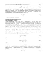
Fig. 27.4
than the rotating sun wheel, the situation is similar, but P becomes the
fulcrum so, although the planet carrier still rotates anti-clockwise, the sun
wheel S
1
rotates in the opposite direction.
Although there are many other forms of planetary gearing, the two described
here are those most commonly used in automotive applications. The broad
principles already explained apply to them all. Heavy duty epicyclic gearing
is to be found mostly in pre-selector and automatic gearboxes and back axle
differentials. In the latter, bevel type planetary gears are usually used for
turning the drive through 90°; they have also the advantage of compactness.
Examples of bevel gear types are illustrated in Chapters 31, 33, and 34, the
clearest being Fig. 34.7. As is explained in those chapters, the terminology
for differentials is different: the planets are housed in a carrier called the
differential cage bolted to the crown wheel. The latter, in effect, is substituted
for the annulus. There are two sun wheels, termed differential gears, one on
the inner end of each halfshaft. These mesh with the planet, or differential,
pinions.
27.3 Epicyclic gear ratios
For ease of recognition of the various gears in all that follows, the annulus
gear is called A, the planet carrier C, the sun gear S, and the planet gear P,
and it is assumed that the gears have respectively A, S and P teeth. If either
end of the planet carrier arm is integral with a tubular shaft and coaxial with
the gear shaft at that end, the arm can be used as either the input or output.
First, take the case of the planet being fixed and the carrier arm, serving
as the input, turned through one revolution, clockwise about the axis of S,
Fig. 27.4(a). If the wheel S were not in mesh with P and were fixed to the
planet arm, it too would have been orbited through 360 °. However, since it
is in mesh with P, it will also have rotated P/S times about its own axis, so
its total rotation will be 1 + P/S revolutions. Therefore, the planet wheel has
20 and the sun wheel 40 teeth, the planet wheel will have turned 1
1
/
2
revolutions
β
α
R
P
D
A
Q
C
β
α
R
Q
A
P
D
C
(b)
(c)
796 The Motor Vehicle
for 1 revolution of the carrier arm, so the gear ratio of this arrangement is
1.5:1.
Now consider the situation if the sun wheel S is fixed, with the carrier,
still the input, rotating around it, Fig. 27.4(b). In this case, the planet wheel
P will have turned 1 + S/P, giving a gear ratio of 1 + 40/20 = 3 : 1.
Finally, if the carrier arm is fixed and P is rotated, the ratio is P/S, giving
a gear ratio of 0.5 : 1, but if S is rotated, the ratio is A/P giving a ratio of 2 : 1.
Note that, in both instances, the driven and driving gears rotate in opposite
directions.
With such an epicyclic arrangement, therefore, it is possible to obtain four
different ratios, simply by applying a brake or clutch to stop one of the
elements in the gear train. This, however, is not of much significance for
automotive transmissions because the space it takes up is similar to that
obtained with a two shaft gearbox, some of the ratios are unsuitable and, in
any case, it becomes more complex if a reverse gear is to be provided.
27.4 Simple planetary epicyclic gearing
For automotive applications, a coaxial layout comprising an annulus gear
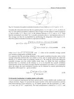
with planet gear, or gears, and a sun gear is widely used. From Fig. 27.5(a),
it can be seen that, if the annulus A is locked, and the input is clockwise
through the sun gear S, the latter will rotate the planet gear anti-clockwise,
so it will roll around the stationary annulus and therefore drive the planet
carrier clockwise. The speed of the planet gear carrier will be:
S/(S + A) (1)
so, if the sun gear has 40 and the annulus 80 teeth the gear ratio will be
40/(40 + 80) = 1/3. In other words, this arrangement will give a reduction of
3.0 : 1. However, if the drive is from A to S instead of S to A, the result will
be an overdrive ratio of 0.33 : 1. Note that the planet gear, rotating in the
direction opposite to that of the sun gear, is simply an idler and therefore has
no influence on the gear ratio.
If, on the other hand, the planet carrier C is locked, and the input is still
the sun gear, Fig. 27.5(b), the output will, of course, be the annulus which is
driven, through the idling planet gear, anti-clockwise. The gear ratio is:
S/A (2)
Brake onBrake on Brake off Brake off Brake on
A
A
A
A
SS
S
S
Drive Locked
Drive
Locked
(c) (d)(b)(a)
Fig. 27.5
C
C
C
C
P
P
P
P
Drive
Drive
797Epicyclic and pre-selector gearboxes
so S will drive P anti-clockwise and this, in turn, will drive the annulus anti-
clockwise at a speed of S/A times that of S, giving a ratio of 40/80 = 1/2 : 1.
In other words, for one revolution of the sun gear, the annulus will rotate half
a revolution (a reduction ratio of 2 : 1).
With the sun gear locked, and the input from the planet carrier, Fig.
27.5(c), the annulus gear A is driven faster in the same direction. The gear
ratio is:
(S + A)/A (3)
the planet and annulus gears rotate in the same direction and the ratio is
120/80 = 1.5 : 1, so the annulus is rotated one and a half turns for every turn
of the planet carrier.
If the annulus gear A is locked and the planet carrier C is the input, Fig.
27.5 (d), the annulus is driven in the same direction. Again the gear ratio is:
(S + A)/A (4)
and the ratio is 1.5 : 1.
27.5 Simple planet epicyclic gearing in general
From the foregoing, it can be concluded that, with an epicyclic gear train
comprising an annulus, sun gear and planet carrier, any one of these can be
fixed and the drive inputted through one of the other two, then the third will
be driven at a different speed. The characteristics of such a gear train are as
follows:
1. The output can be driven at a reduced speed relative to the input and in
the same direction.
2. The output can be driven at a higher speed in the same direction.
3. The output can be driven at an alternative higher speed in the same
direction.
4. The output can be driven at a lower speed than the input but in the
opposite direction, to provide a reverse gear.
5. If any two of the gears locked together, the third cannot rotate relative
to the others so the whole system turns as one solid mass, giving direct
drive at a 1 : 1 ratio.
6. All ratios are dependent upon only the numbers of teeth on the sun and
annulus gears, and are independent of the number of teeth on the planet
gears.
7. With this arrangement, it is therefore possible to have direct drive,
three forward gears, and one reverse gear.
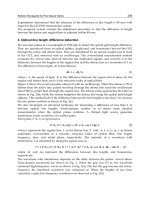
27.6 Compound planet epicyclic gearing
An alternative to Fig. 27.3, in which two integral idler gears are used, is to
have two independent but intermeshing planetary idler gears, one meshing
with the sun and the other with the annulus, Fig. 27.6(a), in which case the
gear ratio between these two comes into play. Consequently, if the annulus
is fixed, the sun gear is the input and the planet carrier the output, the gear
ratio is:
P
1
/P
2
× S/(S + A) (5)
798 The Motor Vehicle
so, if A had 80 teeth, P
1
10, P
2
20 and S 40, the overall ratio would be that
of the two planet gears times that in equation (1), which is 10/20 × 40/(40 +
80) = 0.5 × 0.33 = 0.166 : 1. Note that equation (5) is equation (1) multiplied
by the planet gear ratio.
It follows that to find the ratios in the other cases, all that is necessary is
to multiply the ratios obtained in equations (2), (3) and (4) by the planet gear
ratio. However, because there are two intermeshing planet gears, the output
will rotate in the opposite direction to that previously obtained. Indeed, all
epicyclic gear trains fall into two categories: given that the planet carrier is
locked, the first is when the input and output gears rotate in the same direction
and the second when they rotate in opposite directions.
In Fig. 24.6(b), the principle is the same, but one of the two gears is an
integral pair, so we have three planet gears on two wheels, or a compound
planet gear. This arrangement offers the possibility of axially offsetting the
sun gear from the annulus so that a wider choice of planet ratios is obtainable
than would be possible if two separate planets had to be accommodated
between the periphery of the sun gear and the tooth ring in the annulus. With
this three wheel arrangement and, as before, the annulus fixed and the sun
wheel the input, the overall gear ratio is:
P
1
/P
2
× S/(S + A) (6)
In this instance the planet gear P
3
behaves similarly to that in a simple sun–
planet–annulus train except that its speed of rotation is influenced by the
meshing pair of planet gears with which it is associated. Consequently, the
comments that followed equation (5), and those in the subsequent paragraph,
also apply here.
27.7 Numbers of teeth
Assembly of an epicyclic gear train is practicable only if the numbers of
teeth on the gears has been appropriately chosen. For simple planet epicyclic
gearing, the sum of the numbers of teeth on the sun and annulus gears
divided by the number of planet pinions N
PP
must be an integer.
For compound planet epicyclic gearing, and when the direction of rotation
of the input and output are the same, (P
2
× A) – (S × P
3
) divided by N
PP
× H
CF
must be an integer, where H
CF
is the highest common factor between P
2
and
S. If the relative direction of rotation is not the same, (P
2
× A) + (S × P
3
)
divided by N
PP
× H
CF
must be an integer.
During assembly of the gear train, a vernier effect may be experienced,
R
A
P
2
S
A
P
2
P
3
S
R
P
3
P
2
R
P
1
S
(a) (b)
P
1
Fig. 27.6 Double planet pinnions
P
1
799Epicyclic and pre-selector gearboxes
allowing the planet pinions to be inserted incorrectly within the backlash.
This can be avoided if the numbers of teeth on the sunwheel and annulus are
each divisible by the number of planet pinions, and datum teeth on the
planets are marked.
27.8 Another way of applying epicyclic gearing
An alternative to stopping one of the elements of an epicyclic gear train
completely is to reduce its speed of rotation, by connecting it to a resistance
of some sort. An example already mentioned is the differential gear for
splitting the torque equally between two halfshafts driving either the front or
rear road wheels. A particularly interesting application of this principle was
made in 1964 by F. Perkins Ltd (now Varity Perkins). An auxiliary drive
from an engine was geared up and taken through a differential train, to drive
a supercharger. The engine drove the planet carrier and the output was taken
through the annulus see I.Mech.E Auto. Div. paper presented by Dawson and
Hayward on 14 April 1964.
In automotive practice, the brakes or clutches, either pneumatically or
hydraulically actuated, are applied gradually to the appropriate gears. The
object is to vary the relative speeds progressively during the ratio changes
and thus to provide smooth gear shifts. In this way, the need for a separate
pedal-actuated clutch is obviated. In modern transmissions, because they
require much less attention in service, clutches have largely superseded brakes
even though the latter are less costly.
27.9 Epicyclic gearboxes
For car gearboxes, forward gear ratios of from 1 : 1 to about 5 : 1 and one
reverse are needed. Moreover, as explained in Section 25.10, the forward
ratios must be arranged in a geometrical progression.
Epicyclic gearboxes used to be commonly installed in Daimler, Lanchester
and Armstrong Siddeley cars, mostly to provide preselection of gears and to
eliminate the clutch, although the pedal control was retained for changing
gear instead of operating the clutch. However, they have now been superseded
by automatic transmissions with two pedal control. In heavy commercial
vehicles in which optimum fuel economy is an overriding requirement, the
inefficiency of a torque converter is unacceptable so epicyclic gearboxes are
still widely used. For this type of application, extra gear trains are needed for providing
large numbers of gear ratios needed for coping with the heavy loads carried.
As previously stated, given that top speed is direct drive, seven different
drives are obtainable from a simple train comprising a sun, annulus and
carrier. However, this calls for complex construction and, moreover, some of
the ratios are unsuitable.
Consequently, even for cars, an alternative method is better. This entails
interconnecting several epicyclic trains in series, so that suitable ratios can
be selected. Generally, the first train is the primary one, the others modifying
its ratio before transmitting the drive back through the primary planet carrier
to the road wheels. An overall ratio of 1 : 1 is obtainable by locking the
whole set of gear trains together. With such arrangements, the number of
ratios obtainable rises rapidly with the number of trains although, as previously
indicated, some are unsuitable for automotive gearbox applications.
800 The Motor Vehicle
The trains can be all of the same type or of different types. Several
arrangements with spur gears are illustrated in Fig. 27.7, in which the brakes
are labelled B and the clutches C: in practice multi-plate clutches are employed.
The input is on the left and the output on the right. In diagram (a) two simple
trains are in tandem while at (b) two trains with double-sun gears are similarly
arranged.
By making some individual members function as part of two trains, the
arrangement can be simplified, but fewer ratios are obtainable. An example
is shown at (c), where the sun gears are integral and a single planet carrier
serves both trains. With this arrangement, only one clutch is needed, but only
three ratios are obtainable, as compared with four in (a).
At (d) two of the suns S
1
and S
2
are integral and there is a third sun S with
a carrier common to all three sets of planet gears. The sun S and its meshing
planet gear serves both trains. Because S
2
is larger than the driven sun S,
reverse is obtained when brake B
2
is applied and, since S
1
is smaller than S,
a forward drive ratio is obtained when brake B
1
is applied.
A third method of designing an epicyclic gearbox is to compound several
simple epicyclic gear trains. This was the basis of the Wilson transmission,
originally known as the Wilson-Pilcher gearbox, developed at the beginning
of the 20th century. Later Vauxhall Motors worked with Major Wilson to
develop it further but dropped it in 1927, when General Motors took the
company over. Subsequent development was done by the Daimler company
for their cars.
27.10 Basic principle of the Wilson gearbox
A Wilson type gearbox is illustrated in Fig. 27.8(a), and the functioning of
its various secondary trains is shown in (b) to (f). The primary epicyclic gear
train is common to all the ratios. Its sun S1, Fig. 27.8(b), is driven by shaft
D, which is coupled directly to the engine crankshaft, while its planet carrier
C
1
is coupled directly to the transmission line to the road wheels. In other
Fig. 27.7 Epicyclic gearbox arrangements
C
1
B
1
B
1
C
2
B
2
B
2
(a)
(c)
(d)
(b)
B
2
B
1
C
1
B
2
C
2
B
1
C
S
S
1
S
2
C
801Epicyclic and pre-selector gearboxes
words, these two elements are respectively the input and output regardless of
ratio selected. The required gear ratios are obtained by driving the annulus at
different speeds in relation to engine speed. How this is done is as follows.
If engine speed were constant, at 1000 rev/min, and the annulus braked
(zero rev/min), the speed of the carrier would be 1000 × S
1
/(A
1
+ S
1
) where,
in general, A, S and C throughout what follows are the numbers of teeth on
the annulus and sun wheel respectively, as in Section 27.9. If A
1
= 100 and
S
1
= 25, the speed of C
1
= 200 rev/min and the reduction ratio is 5 : 1.
On the other hand if, with engine speed still at 1000 rev/min, the annulus
is driven at 100 rev/min in the same direction as the engine by other elements
in the compounded series of epicyclic gears, the speed of rotation of the sun
gear relative to the annulus would be only 900 rev/min. So the speed of the
planet carrier would be 900 × 25 = 22 500 divided by 125 = 180 rev/min but,
as the carrier would rotate faster because the annulus was rotating, the 100
rev/min of the latter (in these circumstances not multiplied by the sun-to-
planet ratio) must be added, giving 280 rev/min for the speed of the planet
carrier.
Therefore, when the annulus is stationary, the equation in the previous
paragraphs is in fact 0 + (1000 × S
1
/A
1
+ S
1
) and, when the annulus is
rotating at 100 rev/min, it becomes 100 + (1000 × S
1
/A
1
+ S
1
). In more
general terms, the equation is (R
E
– C
A
) × (S
1
/A
1
+ S
1
) + R
A
, where R
A
and
R
E
are respectively the speeds of rotation of the annulus and engine crankshaft.
It follows that, if R
E
had been 200 rev/min, the output speed of the planet
carrier would have been 380 rev/min.
Fig. 27.8 Wilson gear ratios
(a)
(d)
F
A
3
C
2
A
1
C
1
S
3
S
1
A
1
F
G
E
(b)
S
2
C
3
(f)
(c)
A
1
C
1
S
1
C
1
A
4
C
4
S
1
S
4
S
1
C
1
A
1
A
2
C
2
S
2
D
A
2
(e)
802 The Motor Vehicle
If the annulus is driven in the opposite direction, its speed relative to the
crankshaft becomes negative. So given an annulus rotating at a negative
speed of 400 rev/min we have (1000 + 400) × (25/100 + 25) – 400 =
– 120 rev/min, or in other words a reverse gear ratio of 0.12 : 1.
27.11 The auxiliary trains in the Wilson gearbox
As previously indicated, to drive the annulus at different speeds auxiliary
epicyclic gear trains are used. Those for second gear are shown in Fig.
27.8(c). The sun gear S
2
, in common with S
1
adjacent to it, is driven by the
engine, the planet carrier C
2
is coupled to the annulus A
1
and, to obtain
second gear, a brake is applied to the annulus A
2
. So long as this brake is
holding A
2
stationary, the coupled carrier C
2
and annulus A
1
rotate in the
same direction as the engine but at a lower speed. Consequently, C
1
rotates
at a higher speed than it did in first gear when, as described in the second
paragraph of Section 24.10, A
1
was the stationary element. The actual speed
will, of course, depend on the numbers of teeth on the gears involved.
To obtain third gear, Fig. 27.8(d), annulus A
1
and therefore also the planet
carrier C
2
must be made to rotate faster than in second gear. This entails
causing A
2
to rotate in the same direction as the engine, by applying the
brake to drum F to stop S
3
. The other two elements in the second gear train,
C
3
and A
3
, are coupled respectively to A
2
and C
2
. With S
3
fixed and A
3
rotating in the same direction as the engine, C
3
, S
2
and A
2
will also be
rotating in that direction, the last two because C
3
is coupled to A
2
. Consequently,
the speed of rotation of C
2
must be greater than when A
2
was fixed: therefore
annulus A
2
must be rotating faster than in second gear. Again, the actual
speeds depend on the numbers of teeth on the gears.
Direct drive, Fig. 27.8(e), is obtained by sliding the male cone G along the
splines on the shaft D, and locking it in the female cone in the drum F which
is fixed to S
3
. This locks the whole epicyclic gear assembly together, so that
it rotates en bloc.
Obtaining reverse gear, Fig. 27.8(f), entails bringing the fourth epicyclic
train into operation by applying the brake to A
4
. Sun S
4
is fixed to A
1
, and
carrier C
4
is fixed to the driven shaft D. Sun S
1
is driven forwards by the
engine, and the planet pinion, acting as an idler, drives the annulus A
1
, and
with it the sun S
4
, backwards. Since A
4
is braked, S
4
drives the planet carrier
C
4
backwards too. Moreover, since both C
1
and C
4
are fixed to the output
shaft to the road wheels, both have to rotate at the same speed in the same
direction. This speed is in fact determined by the numbers of teeth on A
1
and
S
1
relative to those on S
4
and A
4
, the last mentioned pair determining the
speed of rotation of the annulus A.
This is not easy to visualise, so let us take an example in which S
1
has 25,
A
1
100, S
4
40 and A
4
80 teeth. To represent the conditions in reverse gear,
apply the brake to A
4
, and then rotate C
4
, and with it the integral carrier C
1
,
backwards one revolution. Now consider the sequence of events as this rotary
motion is transmitted through each of the intermeshing gear pairs in turn.
With A
4
fixed, the planet carrier C
4
will rotate S
4
, and with it the annulus A
1
,
backwards 80/40 = 2 revolutions. This, in turn would have rotated S
1
backwards
100/25 = 4 revolutions which, at first sight, appears to make an overall ratio
of 8 : 1. However, the driven shaft has rotated minus 1 turn and the driving
shaft plus 8 turns, so the overall ratio is in fact 7 : 1.
803Epicyclic and pre-selector gearboxes
27.12 The clutches and brakes in the Wilson gearbox
To simplify in Fig. 27.8(e) a cone clutch was shown, but this, of course,
would be too harsh for the purpose. In practice, a pneumatically or hydraulically
actuated multi-plate clutch such as that illustrated in Fig. 27.9 is employed.
The clutch illustrated is air actuated.
A control valve lets fluid under pressure enter cylinder A beneath the
piston, to actuate the lever B. This moves the ring C to the right, about its
pivot D. Mounted on gimbal pivots F (one on each side) within ring C is the
housing E for the ball thrust bearing. Consequently, the axial displacement
of the centre of C causes the ball thrust bearing to compress the clutch plates
between the presser plate G and the clutch hub H, to which are splined the
driving plates of the clutch. The drum K, to which the driven plates are
splined, is in turn splined to the hub of the sun gear S
1
. When the fluid
pressure is released by the control valve, the clutch is released by a set of coil
springs, equally spaced around the hub (only one can be seen in the illustration).
A typical brake, Fig. 27.10, for acting upon the periphery of the annulus
in this type of gearbox has an outer and an inner band, A and B respectively,
having friction linings L. The outer band is anchored by the hooked link D,
and the inner one by the lug F projecting through a slot in the outer band. The
reactions to the brake torque, at these two diametrically opposite anchorage
points, are equal and opposite and therefore do not add to the load on the
bearings on which the annulus rotates. A tie rod G pulls the outer band on to
the inner band, and thus the inner band on to the drum, which is the periphery
of the annulus. Note that the pull of the tie rod on the lower end of the brake
band is reacted by an equal and opposite pull applied by the hook on its
upper end, and the direction of rotation relative to the fixed anchorage point
is such that the brake band is automatically wrapped around the drum. Stop
C actuates an automatic adjustment device for compensating for wear.
The actuation mechanism is shown in more detail in Fig. 27.11 and the
automatic adjustment mechanism in Fig. 27.12. Fluid pressure, in this case
E
F
L
A
C
D
G
L
B
Fig. 27.9 Fig. 27.10
E
C
D
K
S
3
D
E
H
G
A
B
J
C
F
804 The Motor Vehicle
air, on the piston A lifts the piston rod Q in Fig. 27.11. This, in turn, rotates
the lever B about its pivot O. Roller C, on the other end of the lever, moves
along the cam-shaped lower surface of the lever K, termed the bus bar. As it
does so, it lifts the tie rod, G in Fig. 27.10, to apply the brake. The shape of
the cam is such that the initial movement of the lever is rapid, to take up the
clearance between the drum and brake bands. Subsequently, the slope of the
cam is less steep so that the tie lifts more slowly, and the ratio of force on the
piston to the leverage on the tie is therefore greater. This effect is enhanced
by the fact that, as the roller approaches the end of bus bar K, the lever B on
which it is mounted comes up to its top dead centre position, relative to the
axis P of the pivot.
27.13 Automatic compensation for wear
In the upper diagram of Fig. 27.12, the adjustment device is in the ‘brake off’
position and in the lower one it is in the ‘brake on position’ with zero wear
on the lining. Surrounding the round nut screwed on the top of the tie rod G
is a coil spring B. One end of this spring is fixed to a pin projecting upwards
from plate A. It is then coiled several times round the nut and secured to a
second pin, which is fixed to the knife-edge pivot plate J and projects upwards
through a slot in plate A. Plate A is free to rotate relative to the nut H. Each
time the bus bar K, Fig. 27.11, is pulled upwards to apply the brake, the
upper end of the tie rod, and with it the plate-and-spring assembly, moves
over to the left until the lug on plate A just makes contact with the adjacent
stop C, which is C in Fig. 27.10. For all gears except top, where it is fixed
to the gearbox casing, this stop is mounted on the brake band.
When wear has occurred, the stop goes further than just contacting the
lug: it strikes it and, deflecting it, rotates the plate A anti-clockwise. This
uncoils the spring around the nut H, which therefore is then free to rotate,
except that the friction between it and its conical seating in the pivot plate
prevents it from doing so. When the brake is released, however, the coils
tighten around the nut. Then, as the tie rod is lowered and the whole assembly
retracts to the right in the illustration, the plate rotates back to its original
‘brake off’ position, and the lug on the other side of the plate comes up
against the stop D fixed to the casing. At this point, the coil spring grips the
P
K
C
B
O
A
C
A
B
J
G
H
A
D
Fig. 27.11 Fig. 27.12
Q
805Epicyclic and pre-selector gearboxes
nut and, overcoming the friction between it and the plate A, rotates it to
reduce the effective length of the tie rod, and thus takes up the clearance due
to wear between the brake lining and drum.
Wilson type gearboxes are still widely installed in public service vehicles
although, in most instances, gear shifting is effected either semi- or fully
automatically by means of an electronic control system. This ensures that all
gear changes and moving away from rest are effected smoothly. In the semi-
automatic systems, the driver uses a small lever to select the gears, but the
actual shifting and pressures applied to the actuation mechanisms are effected
automatically in relation to the gear selected and factors such as vehicle
speed, engine speed and torque being transmitted. Once a gear is fully engaged,
the pressure actuating the brake and clutch is increased to the maximum, for
prevention of slippage.
806
Chapter 28
Torque converters and
automatic gearboxes
A torque converter is a device which performs a function similar to that of
a gearbox, namely, to increase the torque while reducing the speed, but
whereas a gearbox provides only a small number of fixed ratios the torque
converter provides a continuous variation of ratio from the lowest to the
highest.
Constructionally, a torque converter is somewhat similar to a fluid flywheel
from which it differs in one important aspect, namely, in having three principal
components instead of only two. Torque converters all consist of (a) the
driving element (impeller) which is connected to the engine, (b) the driven
element (rotor) which is connected to the propeller shaft, and (c) the fixed
element (reaction member) which is fixed to the frame. It is the last element
which makes it possible to obtain a change of torque between input and
output shafts and, as has been seen, the fluid flywheel, which does not have
any fixed member, cannot produce any change of torque.
A three-stage torque converter is shown in the several views of Fig. 28.1.
The impeller, shown in sectional perspective at (d), is a conical disc provided
with blades A the outer ends of which are tied together by a ring a. If this
impeller is immersed in fluid and rotated then the fluid between the blades
will be flung out more or less tangentially and a flow will be established
from the centre or eye of the impeller to the periphery. The velocity of a
particle of fluid on leaving the impeller is indicated by the line V
a
in the view
(a); this velocity may be resolved into a purely tangential component V
t
and
a purely radial component V
r
.
The rotor or driven element is sectioned in black in the views (a), (b) and
(c) and is shown in sectional perspective at (f). It consists of a portion similar
to the impeller, comprising the disc member b, which carries the blades F,
and the hollow annular member g which is carried by the blades F and which
in turn carries blades B and D; these latter blades are tied together at their
outer ends by rings as shown.
The fixed, or reaction, member consists of a drum-like casing h fitting the
shaft portions of the impeller and rotor at the centre and thus enclosing those
members. The reaction member carries blades C all round its periphery and
blades E project, in a ring, from the right-hand end wall.
807Torque converters and automatic gearboxes
V
b
v
r
v
a
v
b
A
v
t
Forward
h
SX
C
D
B
A
E
F
h
X
S
′
V
b
V
r
V
t
′
V
c
A
a
a
Impeller
Forward
C
D
b
F
B
Driven
member
V
r
V
c
V
t
Forward
(a)
(b)
(c)
(e)(d) (f)
B
′
V
b
D
E
F
g
Fig. 28.1
The action of the converter is as follows: the fluid flung out at the periphery
of the impeller impinges on the blades B of the rotor and is deflected by
those blades, the tangential component of the velocity of any particle, for
example, V
t
in view (a), being abstracted, more or less completely, so that the
velocity of the particle on leaving the blades B is more or less radial as
indicated by the arrow V
b
. The particle being considered has therefore lost
momentum in the tangential direction and this momentum has been gained
by the blades B, that is, by the rotor. In being deflected backwards by the
blades the fluid applies a pressure forwards on the blades. On leaving the
blades B the fluid is guided round by the fixed casing and enters the blades
C. In passing through these blades the velocity of the particle is changed
from a more or less purely axial velocity, as V
1
b
in views (b) and (e), into a
velocity having a considerable tangential component, as V
t
in view (e). In
deflecting the fluid in this way the blades C, and thus the fixed casing,
receive a backwards thrust and unless the reaction member were fixed these
thrusts would make it rotate backwards. The particle of fluid is now guided
round by the fixed casing and enters the blades D of the rotor with a velocity
V
c
in view (c), which again has a considerable tangential component V
t
and
again on passing through the blades this tangential component is abstracted
and the momentum associated with it is acquired by the rotor. The particle of
fluid now enters the blades E which restore the tangential component of
velocity once more and finally it enters blades F which finally abstract the
tangential momentum, which is acquired by the rotor. The particle of fluid
has now found its way back to the eye of the impeller and cycle commences
all over again.
The rotor or driven element thus receives three driving impulses, one from
the blades B, one from the blades D and one from the blades F, and this
808 The Motor Vehicle
converter is consequently called a three-stage converter.
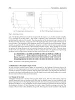
The characteristics of a torque converter of this kind are shown by the
graphs Fig. 28.2(a) and (b).
The graph (a) shows the manner in which the torque increase and efficiency
vary when the rotor speed varies from zero to the maximum value (2700 rev/
min), the impeller speed being constant at 3000 rev/min. When the rotor
speed is zero (because the resistance opposing its motion is large enough to
hold it fixed) the torque tending to rotate it will be nearly
6
1
2
times the
torque developed by the engine at its speed of 3000 rev/min. If the resistance
to the motion of the rotor now decreases so that the rotor starts to rotate, then
as it gathers speed so the driving torque action on it falls off. At a rotor speed
of 1000, for example, the driving torque would have fallen off to about three
times engine torque, at 1900 rev/min the driving torque would be only just
equal to engine torque, while at 2700 rev/min the driving torque would have
fallen to zero. The efficiency on the other hand starts at zero when the rotor
speed is zero, because although the driving torque acting on the rotor is then
large no rotation occurs and the torque does no work; thus no work is being
got out of the converter but a lot of work is being put in by the engine and
so the efficiency is zero. As the rotor speed increases so does the efficiency
and a peak efficiency of 86 to 90% is reached at a rotor speed of about 1000
Torque ratio
Efficiency
7
6
5
4
3
2
1
0
Ratio
Output torque
Input torque
500 1000 1500 2000 2500 3000
Output speed rev/min
(a)
Input speed 3000 rev/min
100
80
60
40
20
Ratio
Output torque
Input torque
5
4
3
2
1
0
Torque ratio
Efficiency
Efficiency %
100
80
60
40
20
Efficiency %
500 1000 1500 2000
Output speed rev/min
Fig. 28.2
(b)
Input speed 2000 rev/min
809Torque converters and automatic gearboxes
rev/min. As the rotor speed continues to increase the efficiency falls off
again and at 2700 rev/min becomes zero once more, this time because although
the rotor is revolving rapidly the driving torque on it is zero and no work can
be got out of it.
The graph (b) shows the same things but for an impeller speed of 2000
rev/min instead of 3000 rev/min. It will be seen that the driving torque acting
on the rotor when it is stalled, that is, held at rest, is now only
4
1
3
times
engine torque and it falls off to zero at a rotor speed of 1800 rev/min. The
efficiency reaches a maximum value of only about 80% instead of 85 to
90%.
It is thus seen that only over a rather narrow range of rotor speeds is the
efficiency reasonably good and it must be borne in mind that if the efficiency
is, say, 60%, then 40% of the power developed by the engine is wasted, being
converted into heat which raises the temperature of the torque converter fluid
and which has to be dissipated by some means, commonly a radiator. The
fall-off of efficiency at the low speed end of the range can be tolerated
because those speeds are normally used only for short periods when starting
and climbing severe hills, but the fall-off at high speeds cannot be tolerated
and must be circumvented. There are two principal ways in which this can be
done, (a) by substituting a direct drive for the torque converter at high speeds
and (b) by making the torque converter function as a fluid flywheel at the
higher speeds.
28.1 Torque converter with direct drive
Referring to Fig. 28.3, a double clutch, provided with two separate driven
plates A and B, is situated between the engine and the torque converter (TC),
only the impeller and part of the rotor of which are shown. The plate A is
connected to the shaft C which is permanently coupled to the propeller shaft
while the plate B is connected to the impeller of the torque converter. The
rotor of the latter is connected through the freewheel D to the shaft C and
thus to the output shaft. The intermediate plate E of the clutch can be pressed
either to the left or to the right. When pressed to the right it grips the plate
B and thus drives the impeller of the torque converter and the drive passes
through the torque converter and the freewheel D to the output. If now the
plate E is pressed to the left the plate B (and torque converter) will no longer
be driven but the drive will pass direct through plate A to the shaft C and
output which will override the rollers of the freewheel D; the rotor of the
torque converter will thus come to rest. The efficiency of the direct drive is
100% and the combined efficiency curve will be as shown in Fig. 28.4. The
E
A
B
C
TC
D
Fig. 28.3
810 The Motor Vehicle
change-over from converter to direct drive is done by the operation of a lever
or pedal by the driver. Three-stage converters are no longer used in road
vehicles because single-stage ones used in conjunction with gearboxes have
been found adequate.
28.2 Turbo-Transmitters converter
The second method of obviating the fall-off in efficiency at the higher output
speeds is used in the Turbo-transmitters converter unit shown diagrammatically
in Fig. 28.5.
The impeller is seen at A and is permanently connected to the engine
crankshaft; it differs from that of the unit shown in Fig. 28.3 in having blades
that extend over nearly half of the complete fluid circuit instead of over only
about a quarter of that circuit. The impeller thus more nearly resembles the
impeller of a fluid flywheel from which it differs chiefly in having blades
that are curved in the end view whereas the blades of a fluid flywheel
impeller are straight. The driven member, shown sectioned in solid black,
has two sets of blades B and C and is fixed to the output shaft D. The reaction
member also has two sets of blades E and F. The blade unit E is carried on
the unit F on which it is free to rotate in the forwards direction but is
prevented from rotating backwards by pawls that engage ratchet teeth of F.
The member F in turn is free to rotate on the fixed member G but again only
in the forwards direction. Backwards rotation is prevented by a multi-plate
clutch, situated at H, which engages and locks F to G whenever the member
F tries to rotate backwards but which disengages when F tries to go forwards,
which motion is thus allowed. This clutch is shown in Fig. 28.7. The converter
is a two-stage one, two driving impulses being given to the driven member,
one when the direction of the fluid is changed in the blades B and a second
when the direction of the fluid is changed in the blades C. When the torque
acting on the driven member BCD is greater than the engine torque applied
to the driving member A, there will be a reaction torque acting on the blades
E and F; this will be transmitted by the pawls and ratchet teeth from E to F
and by the clutch at H to the member G. Whenever the torque acting on the
blades B and C tends to fall below the torque applied to A, a forwards torque
will be applied to the blades E and F; this will merely cause those blades to
rotate forwards and the converter will then function as a fluid flywheel; the
percentage slip will then be quite small, say about 5 or 6%, and will decrease
as the speed of the driven member increases.
Change-over point
Output speed
Efficiency %
100
E
B
A
C
F
G
H
D
Fig. 28.4 Fig. 28.5
811Torque converters and automatic gearboxes
5
4
3
2
1
0
1000 2000
100
80
60
40
20
0
Output speed Rev/Min
Change-over point
Efficiency
Torque ratio
Efficiency %
Fig. 28.6
E
F
B
D
A
G
C
D
R
I
G
G
Fig. 28.7 Fig. 28.8
Ratio
Output torque
Input torque
The characteristics of this converter will thus be somewhat as shown in
Fig. 28.6, which shows torque increase and efficiency curves for an input
speed of 3500 rev/min. The converter being only a two-stage one, the maximum
torque is only about four times engine torque as compared with
6
1
2
to seven
in the Leyland converter, but otherwise the curves are very similar in general
shape. The change-over point, at which the reaction members E and F begin
to rotate forwards, and the unit commences to function as a fluid flywheel,
is at 1200 rev/min, and from that speed onwards the output will be
approximately equal to the input torque and the output speed will be only
some 5 or 6% less than engine speed.
When the engine speed is less than the maximum 3500 rev/min assumed
above, and when the throttle opening is reduced so that the engine torque is
less than maximum, then the change-over speed will be lower than the 1200
rev/min corresponding to maximum engine speed and torque.
The fact that the change-over is quite automatic is important and is
responsible for the good performance of this type of converter at part throttle
loads and medium engine speeds.
28.3 Other arrangements of torque converters
Four arrangements of single-stage converters are shown in Figs 28.8 to 28.11.
812 The Motor Vehicle
In Fig. 28.8 the reaction member R is permanently fixed, which makes it
unsuitable for use in motor vehicles unless some form of direct drive is
provided and the converter is emptied when the direct drive is engaged.
The design shown in Fig 28.9 is widely used, being simple constructionally;
the one-way clutch S is sometimes placed outside the casing by providing
the reaction member with a sleeve which passes through the cover of the
impeller member.
In Fig. 28.10 an auxiliary impeller I
2
is provided and is carried on a one-
way clutch S
3
on the main impeller I
1
; the reaction member is also divided
into two portions R
1
and R
2
, each of which is anchored separately by the
one-way clutches S
1
and S
2
. Thus arrangement, which was introduced on
Buick cars some years ago, is claimed to increase the efficiency of the
converter and to make the change-over to coupling action smoother.
In the Borgward converter shown in Fig. 28.11 the whole reaction member
RR
1
and the impeller I on which the reaction member is mounted on ball
bearings B, is moved to the left when engaging the cone clutch H and is done
by the reaction of the pressure that exists inside the coupling at L and which
acts on the exposed area of the driven member D. To obtain direct drive, oil
under pressure from the gearbox control unit is passed to the space K and
D
I
R
G
S
D
R
1
S
2
S
3
G
R
2
I
2
I
1
S
1
Fig. 28.9 Fig. 28.10
H
R
LD
I
M
K
G
E
S
G
B
C
A
C
D
1
I
D
2
R
S
G
Fig. 28.11 Fig. 28.12
R
1
813Torque converters and automatic gearboxes
moves the reaction member and impeller to the right so as to engage the cone
clutch M. The one-way clutch S enables the output member E to drive the
impleller, and thus the engine, in the forwards direction and so permits the
engine to be used as a brake or to be started by towing the car.
The arrangement of a two-stage converter shown in Fig. 28.12 differs
from that of Fig. 28.5 in that only a single reaction member is used and so
the second driven member D
2
, which is bolted up to the member D
1
, discharges
direct into the inlet of the impeller. The single-plate clutch C gives a direct
drive when it is required; the method of engaging the clutch is not shown but
various means are used; a very convenient one when the converter is associated
with an automatic gearbox is to make the pressure plate of the clutch function
as a piston in a cylinder formed in the flywheel and to engage the clutch by
admitting pressure oil to this cylinder.
28.4 Chevrolet Turboglide transmission
This is a combination of a converter and an epicyclic gear and is shown in
Fig. 28.13. The converter has five elements, the pump P, three turbine or
driven elements T
1
, T
2
and T
3
, and a reaction member R. The latter is free to
rotate in the forward direction on the freewheel F
1
and is provided with a set
of blades B, whose angles are adjustable; The mechanism for making the
adjustment is not indicated.
The first turbine element T
1
is coupled by the shaft D to the sun S
2
of the
second epicyclic train; the second turbine T
2
is coupled through the sleeve E
to the annulus A
1
of the first epicyclic train and the third turbine T
3
is
coupled to the output shaft H by the sleeve G
1
, the clutch C
1
(which is always
engaged except when neutral and reverse are selected), the sleeve G
2
and the
planet carrier R
2
. The sun S
1
is normally prevented from rotating backwards
by the freewheel F
2
, since usually the clutch C
2
is engaged and the member
K is fixed so that the sleeve J cannot rotate backwards. The annulus A
2
is also
prevented from rotating backwards by the freewheel F
3
which locks it for
such rotation to the sleeve J. Engagement of the clutch C
3
fixes the annulus
A
2
against forwards or backwards rotation, and this is done when ‘low’ is
selected so as to reduce the load on the freewheel F
3
, when the engine is
T
2
T
1
T
3
B
H
R
2
A
2
Fixed casing
P
R
C
3
C
4
C
1
A
1
C
2
K
F
2
J
F
3
L
R
1
D
12
S
2
G
2
S
1
G
1
F
1
D
E
Fig. 28.13
814 The Motor Vehicle
pulling hard under adverse road conditions, and to allow the engine to be
used effectively as a brake on down gradients.
At low forward speeds of the output shaft H relative to the engine speed,
the sun S
1
and annulus A
2
will be stationary because the torques on them will
tend to make them rotate backwards and this motion is prevented by the
freewheels F
2
and F
3
. Both epicyclic trains then provide speed reductions
and torque increases, and all three turbines will be driving.
As the output speed rises, the torque passing through the sun S
2
will fall
and at some point will tend to become negative, and then the annulus A
2
will
start to rotate forwards and the turbine T
1
will be effectively out of action. At
a higher output shaft speed, the sun S
1
will start to rotate forwards and the
turbine T
2
will go out of action. The drive will then be through T
3
direct to
the output shaft, the only torque magnification then being that due to the
torque converter itself. Finally, the reaction member R will start to rotate
forwards and the torque converter will run as a fluid coupling. The speeds
and torques at which these events occur will depend on the angle at which
the blades B are set.
Reverse is obtained by engaging the clutch C
4
and disengaging C
1
, C
2
and
C
3
. The trains 1 and 2 are then compounded and give a reverse ratio, the
whole of the driving torque being transmitted by the turbine T
1
and sun S
2
.
Forward motion of S
2
tends to drive R
2
forwards and A
2
backwards; backward
motion of A
2
, however, results in backward motion of S
1
(through the freewheel
F
3
and the sleeve J) and so in train 1, whose annulus is fixed, the sun tends
to rotate the planet carrier R
1
backwards. The backward torque on R
1
is
greater than the forward torque on R
2
(from S
2
), and so R
1
and R
2
will move
backwards.
28.5 Torque converter performance
How torque converter performance should be matched to engine performance
depends on the type of vehicle. For instance, in a family saloon the emphasis
might be placed on attaining a high top speed whereas, for sports cars, high
torque at low speed, for good acceleration from take-off, might be more
desirable. The latter was the requirement for the Porsche Carrera 2, described
in detail in Section 28.9, which exemplifies the problems and their solutions.
In this instance, to obtain the desired acceleration at low speeds, the overall
transmission ratio selected was such that, at maximum vehicle speed, the
engine speed exceeds its nominal value by between 5% and 7%.
As can be seen from Figs 28.6, 28.14 and 28.15, with a practicable conversion
ratio, a soft torque converter is needed for attaining high torque at the road
wheels at high engine speeds. On the other hand, to obtain instant response
to variations in engine torque, or load, a stiff converter is needed. Moreover,
at high altitudes, engine torque may be reduced by as much as 20%, with a
corresponding reduction in acceleration from rest. This effect is especially
noticeable at and beyond the coupling point, when the converter becomes, in
effect, a fluid flywheel.
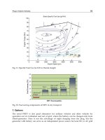
In Fig. 28.14, steady state power losses in fourth gear have been plotted
against vehicle speed for the Porsche Carrera 2. These curves demonstrate
the degree to which, when torque conversion is taking place at low speeds,
converter slip causes power losses and therefore increases fuel consumption.
Beyond the coupling point, the power transmission efficiency with the vehicle
815Torque converters and automatic gearboxes
18
16
12
8
4
0
0 40 80 120 180 220 240
Vehicle speed, km/h
5%
15% upgrade
10%
Full load
h = 0.85 (coupling point)
h = 0.9
h = 0.95
Plane
h = 0.98
Power loss, kW
Fig. 28.14 Converter power loss in fourth gear at steady speed with the lock-up clutch
disengaged
Lock-up clutch
engaged
Dynamic slip limit
Lock-up points
at full load
1st gear
3rd
4th
2nd
10
5
0
Acceleration, m/sec
2
0 50 100 150 200 250 300
Vehicle speed, km/h
Fig. 28.15 Acceleration potential with torque converter engaged and disengaged
accelerating modestly at constant engine speed, ranges from 90% to 80%.
Below the coupling point, as loads increase and speeds fall off, converter slip
increases and efficiency declines. This, of course, is why a lock-up clutch is
installed.
The best lock-up point is the engine speed at which maximum torque is
developed, Fig. 28.15. Up to this point, optimum acceleration is obtained
with torque conversion. Beyond the coupling point, more power is transmitted
to the road wheels if the lock-up clutch is engaged and, in this condition, the
overall fuel consumption is best at the lower end of the engine speed range.
However, comfort can be impaired during gear shifting with lock-up engaged
so, if comfort and driveability during shifts are to be maintained, conversion
may have to be introduced for gear shifting at low speeds. Without lock-up,
optimum fuel consumption is dependent upon not only the engine and converter
efficiencies, but also the efficiencies in each gear ratio in both the up and
down shift modes, as well as the need to avoid excessive shift frequency. For
the Porsche Carrera 2, the penalty for setting the lock-up points in the
low speed range to obtain low fuel consumption was an increase in 0 to
100 km/h time of 6.5 to 6.6 sec, a mere 0.1%.
Lock-up clutch
disengaged
816 The Motor Vehicle
28.6 Automatic transmission in general
In the USA, the first automatic transmission with a torque converter and
epicyclic gearing was introduced in the mid-1930s and, in Europe, in 1950.
Simple automatic systems may be refined by the inclusion of facilities for
changing the gear range to cope with difficult conditions, such as on rough
terrain or in heavy traffic, and for inhibiting upward changes, for example
when ascending steep gradients. The latter facility can be used to avoid
repeated up and down changes on such gradients. To provide the different
ratios required, all these automatic transmissions feature a mechanical gearbox,
mostly epicyclic, and usually with a torque converter, through which the
drive is transmitted to the mechanical gearbox. Since the introduction of
electronics for road vehicles, the trend has been towards ever increasing
sophistication of control.
Even the earlier systems can perform better and more efficiently than the
average driver. However, very competent drivers using a good manual gearbox
can obtain more satisfactory performance than with most automatic gearboxes,
even with electronic control. In general, the control must bring about changes
from low to high ratios as the vehicle speed rises, and from high to low as it
falls. However, it is frequently possible to employ the higher gears even at
low vehicle speeds, for example on level roads and with following winds,
when the resistances to be overcome are low.
The control system must therefore take account of the engine load and, in
general, produce changes up when the load is light and changes down when
the load is heavy. There are, however, occasions, such as on descending hills,
when it is desirable to employ a low gear although the load on the engine
may be nil or the engine may be acting as a brake. It is under these diverse
conditions that the human element has to be retained in the control.
All automatic transmission systems are controlled with reference to vehicle
speed and engine load. With electronic control, however, additional factors
may be introduced, such as engine temperature, ambient temperature, icy
road conditions, and rate of change of accelerator position. These data are
obtained by the use of sensors which, in the earlier systems, were mechanical,
electrical, pneumatic (manifold depression). Now, however, electronic sensors
predominate.
As previously indicated, the fuel consumption of an automatic transmission
embodying a torque converter is inherently higher than that of the equivalent
manually controlled transmission. This is attributable to factors such as friction
losses in the multi-plate clutches and brakes used to change gear ratios,
losses in their hydraulic control systems, converter losses, and friction losses
in the gears and preloaded rolling element bearings.
It is essential that the vehicle speed, at which any change from a lower
gear to a higher one is produced when the vehicle speed is rising and the
accelerator pedal position is constant, shall be higher than the speed at which,
when the speed is falling and the accelerator pedal position is unchanged, the
corresponding change down will occur. If this is not so, a change up is likely
to be followed immediately by a change down, and this sequence may go on
indefinitely. This phenomenon is known as hunting. It is also generally desirable
that in traffic, when the accelerator pedal is released and the vehicle comes
to rest, the control system shall produce all the changes down from top to
bottom, but shall retain the gear that is in use when the accelerator pedal is
817Torque converters and automatic gearboxes
released until the vehicle speed has fallen nearly to zero, and shall then
engage the low gear ready for the ensuing acceleration. It is also desirable
that it shall be possible to start off in first or in second gear according to the
prevailing road conditions.
The above considerations should be borne in mind when reading the
descriptions of the systems that follow since many of their apparent compli-
cations are due to the necessity to comply with the requirements outlined
above. In automotive applications, torque conversion ratios of between 2.0 : 1
and 2.5 : 1 are most common, hydraulic efficiencies rise to about 97 or 98%
at high speed, and slip at the coupling point is of the order of 10% to 15%.
28.7 Borg-Warner Models 35, 65 and 66 transmissions
Model 35 is shown in Figs 28.16 and 28.17. It consists of a single-stage
torque converter IDR coupled to a three forward and one reverse ratio epicyclic
gear. The driven member D of the converter is, in effect, integral with the
drums E and G of the clutches C
1
and C
2
. When C
1
is engaged the drive goes
to the sun S
2
and if the brake B
2
is applied gives the low forward ratio while
if the brake B
1
is applied instead of B
2
then the immediate ratio is obtained.
The one-way sprag clutch F prevents the planet carrier R from rotating
backwards but allows it to rotate forwards. By engaging both clutches C
1
and
C
2
simultaneously the gear is locked soild and the direct drive is obtained. To
get reverse the clutch C
2
is engaged and the brake B
2
is applied, the drive
then goes from S
1
to P
1
and thence to the annulus A, the planet carrier being
fixed.
The teeth seen on the outside of the annulus in Fig. 28.17 are engaged by
a detent when the control lever is put into the parking position and this holds
the car stationary. Two oil pumps provide the oil pressures required to engage
the clutches and apply the brakes. One is housed in the left-hand end of the
box and is driven off the sleeve of the impeller so that it is working whenever
the engine is running while the other is seen at the right-hand side and is
driven off the output shaft of the box so that it will be running when the car
is in motion. The principle underlying the action of the control system is
R
D
I
Casing
E
H
B
1
B
2
P
1
A
G
C
2
C
1
S
1
S
2
P
2
R
F
Fig. 28.16
818 The Motor Vehicle
similar to that of the Hydramatic boxes which are described in Section
28.13.
In principle, the Model 65 is similar to the Model 35, which went out of
production about 1974. Their gearsets are virtually identical, though that of
the 65 is designed for heavier duty. Detail modifications have improved the
quality of operation and, by lowering the brake actuation cylinders to a level
below the brake bands and bringing them into the casing, the overall width
of the transmission has been significantly reduced.
Further development of the Model 65 resulted in the introduction of the
Model 66, which is designed for even heavier duty or for a higher level of
durability in cars at the upper end of the market range. The shafting has been
strengthened, and the lubrication system improved by fitting a deeper oil pan
and enlarging some of the ducts. Externally, however, the dimensions remain
the same.
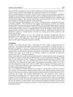
28.8 Alfa Romeo Q-System
An advanced automatic control system, based on the Aisin transmission, is
fitted to the Alfa Romeo 156 with a V6 engine. It provides three different
driving modes, ‘Sport, City and lce’, plus one two-pedal ‘Manual’ mode,
which Alfa Romeo call the Q-System function. Manual mode is selected by
moving the gear shift lever to the left, into the centre of a conventional H-
gate giving four forward ratios. Reverse can be obtained only in automatic
mode. To select automatic, the lever has to be moved into the right-hand
gate, where it can be pulled straight back to shift from park (P) to reverse
(R), and on in the same direction through neutral (N) to drive (D). Holding
low gear ratios can be done only by selecting manual.
Fig. 28.17
819Torque converters and automatic gearboxes
Mode changes are effected by depressing one of the two buttons on the
central console; one is marked ‘Ice’ and the other, marked ‘C/S’, is for
toggling between ‘City’ and ‘Sport’. In City mode, each upward shift is
effected at relatively low rev/min to provide occupant comfort combined
with the best fuel economy that can be reasonably obtained under these
conditions. Sport is for driving on the open road where a lively performance
is required. When Ice is selected, the gears are shifted at lower vehicle
speeds than those for normal driving. This is to avoid sudden changes in
torque at the road wheels, which, of course, could initiate skids on icy
surfaces. Kick-down acceleration is inhibited in the Ice mode. Manual is for
use in special situations and to satisfy the demands of drivers who prefer to
be directly in control.
A liquid crystal window on the engine speed indicator dial indicates which
mode and gear are engaged. The indications in the automatic modes are:
‘
CITY D’, ‘ICE D’ and ‘SPORT D’. In manual mode, only the number of the gear
selected is displayed.
The engine can be started only with the gear lever in either P or N. To start
the vehicle moving, it is necessary to depress the brake pedal and then, if the
lever is in the P position, lift the release device beneath its knob to change
into the drive or reverse mode. Selection of R is always indicated by an
acoustic signal, and a similar signal is sounded if the brake pedal has not
been depressed or a door is open. As the accelerator is depressed and the
brake pedal released, the car begins to move.
With further depression of the accelerator pedal and increasing speed, the
electronic system signals the appropriate gear changes, which are effected
through the medium of the torque converter. If the accelerator is pressed
down to the floor, a kick-down function comes into play, changing down for
rapid acceleration during, for example, overtaking. When the pedal is released,
the system reverts to the ratio appropriate for the mode in operation. If a
change from automatic to manual mode is made while the vehicle is in
motion, the electronic control system automatically changes to the ratio
appropriate for the speeds of the vehicle and its engine. Should there be any
danger of overspeeding of the engine, this mode change is inhibited.
A number of safety features are embodied in the system. For example, to
discourage the driver from parking the vehicle in N, the ignition key can be
withdrawn only with the gear lever in the P position. In an emergency,
however, the driver can remove the key after depressing a release button
adjacent to the ignition lock. Moreover, to avoid the possibility of inappropriate
movements of the vehicle when setting off on a steep slope, the lever can be
released from the P position only after first depressing the brake pedal.
Selection of R is inhibited if the engine speed is too high, although it then
engages automatically when the speed falls to an appropriate level. In addition
to indicating reverse gear engaged or door open, the acoustic signal sounds
if the engine is off and the lever not set to P.
28.9 Porsche automatic transmission for sports cars
The Tiptronic automatic transmission is based on the ZF 4HP 22 EH four-
speed planetary transmission. As fitted to the Porsche Carrera 2, it is of
especial interest because it has been designed specifically for a sports car.
Hitherto, automatic transmissions embodying alternative economy or sporty