The Motor Vehicle 2010 Part 9 ppsx
Bạn đang xem bản rút gọn của tài liệu. Xem và tải ngay bản đầy đủ của tài liệu tại đây (1.06 MB, 70 trang )
584 The Motor Vehicle
car operated under the LA4 US Federal Test Procedure, the supercharger
would be operating for only 6% and, during the Highway Cycle, only 5.5%
of the total time. Therefore, durability of the supercharger should not be a
problem, though the same comment would not necessarily apply to the clutch.
Fuel economies of the order of 13% relative to that of a naturally aspirated
engine developing the same maximum power should be obtainable.
16.25 Screw-type compressors
The first screw-type compressor was developed by Krigar in 1878. In the
early nineteen-forties, two compressors of similar type were introduced for
supercharging the internal combustion engine. One was the invention of A.
J. R. Lysholm, of Ljungstrøms Angturbin, Sweden, and the other the unit
produced by the Saurer company in Switzerland. In each, spiral lobes on a
male rotor meshed with grooves in a female rotor, as shown in Figs 16.24
and 16.25. The spiral on one rotor is left- and that on the other right-handed,
the two rotating in opposite directions.
During the rotation, air is drawn through the inlet port, in one end of the
casing, where it enters the spaces between, one after the other in turn, the
spiral grooves on the female and their meshing lobes on the male rotor. This
is the induction phase of the cycle, because the lobe that is beginning to
uncover the port is also beginning to withdraw from its groove, so the space
between each meshing pair is increasing, allowing the air at atmospheric
pressure to enter. As rotation continues, this air is carried around by the
grooves in the female rotor until the inlet port is covered by its leading edge.
This is the beginning of the compression phase, because the lobe is beginning
to mesh into the groove, at the inlet end, and thereafter progressively compresses
and displaces the air towards the far end of the casing. Finally, the delivery
12
10
8
6
4
2
0
20 30 40 50 60 70 80
350
260
275
300
400
80% naturally aspirated torque
300
270 275 300
Bmep, bar
360
Engine speed, rev/s
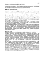
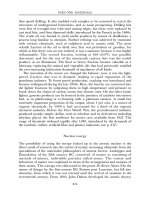
Fig. 16.23 Plots of estimated bsfc of a 1.7-litre diesel engine supercharged by a roots-
type blower cut out by a clutch as the load falls below 80% of maximum torque
(reported by Freese and Nightingale of Ricardo Consulting Engineers Ltd)
585Turbocharging and supercharging
phase begins as the trailing edge of the groove uncovers the port in the
opposite end, whence the air is delivered into the induction manifold. Because
the air is compressed before delivery, there is no back-flow so the only
significant noise is a high pitched whine due to meshing of the rotors. By
virtue of the incorporation of several lobes and grooves, and progressive
compression from one end to the other, delivery is practically pulse free.
The Sprintex unit, which can operate at pressure ratios of up to about
2.2 :1, is a good example of a modern screw-type compressor. Its rotors are
coated with PTFE and, by virtue of extremely close tolerances and a tip
clearance of only 100
µ
m, the lobes touch neither the grooves nor the casing.
Their rotation is accurately synchronised because they are interlinked by a
pair of gears in a housing at one end of the main casing. The range currently
in production provides for maximum flow rates of 130 to 3301/s.
In order to obtain good helical (or axial) sealing, a low addendum (distance
between pitch circle and periphery of rotor) is necessary. To achieve this
with male and female rotors having equal numbers of lobes and grooves, the
female would have to very small. This condition has been avoided in the
Sprintex units by having two more grooves than lobes, which provides a high
displacement for any given speed. Sprintex machines operate at higher speeds
than most other superchargers. Driving the female rotor limits the crankshaft
to supercharger drive ratio and thus reduces the space needed for accommo-
dating the crankshaft pulleys. Volumetric efficiencies of these units peak at
a rotor tip speed of about 100 m/s and thereafter fall gradually, as compared
with, for example, the roots type, which peak at about 50 m/s and then fall
sharply.
Matching to the engine is relatively simple since the output of the
supercharger and air consumption of a four-stroke engine are both linearly
proportional to speed. The first step therefore is to pick the size of supercharger
the air throughput of which matches the consumption rate of the engine.
Fig. 16.24 General section of Saurer rotors Fig. 16.25 Saurer rotors
586 The Motor Vehicle
M
d
C
T
2
D
L
m
P
e
C
T
2
D
L
m
N
e
C
T
2
D
Lm
p
e
C
T
2
D
b
e
C
T
2
D
L
m
b
e
C
T
2
D
N
e
C
T
2
D
M
d
CT2D
However, some adjustment may then have to be made because the volumetric
efficiencies of the engine and supercharger vary differently with speed and
pressure. The two-stroke engine calls for a slightly different approach, since
pressures and flows have to be related to the additional air requirements of
scavenging.
With internal compression, a by-pass valve does not offer the same advantage
as with the displacement type, since the work done in compressing the air
would be wasted. However, the efficiency of compression is higher, and
some economy could be obtained by incorporating a clutch in the drive.
Figures quoted by FTD, who developed the Sprintex compressor, indicate
that the adiabatic compression efficiencies of the roots type, Sprintex unit
and a turbocharger approximate to respectively 30 to 50%, 70 to 75% and 60
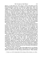
to 65%. An adiabatic efficiency of 80% has been claimed for the Saurer unit
operating at a pressure ratio of 1.5 :1 at 5000 rev/min, and pressure ratios of
up to 2.0 :1 are said to be obtainable at up to 10 000 rev/min. Some performance
curves for this compressor are shown in Fig. 16.26.
16.26 Other methods of supercharging
A method that, prior to the Second World War, was fairly widely used for
two-stroke engines was to have double the number of cylinders needed for
generating the power required. The additional cylinders were used for
compressing the air for scavenging and pressure charging those adjacent to
them. Well-known examples were the Trojan engines, Section 9.5. This method,
however, considerably adds to the bulk, weight and cost of the engine.
80
70
60
50
11
10
9
8
7
190
180
170
160
800 1000 1200 1400 1600 1800 2000
170
160
150
140
130
120
110
100
90
80
70
60
R.p.m.
b
e
–g/PSh P
e
–kg/cm
2
Md–m-kg
Fig. 16.26 Performance curves for the
Saurer supercharger
N
e
–PS
587Turbocharging and supercharging
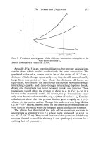
In the nineteen-eighties, KKK developed their Ro-Charger, Fig. 16.27. It
has two rotors, one inside the other. The inner one is of a figure-of-eight, or
dumb-bell, section and is mounted on the driven shaft. This shaft is carried
in a pair of sealed-for-life bearings at the driven end and a single bearing at
the opposite end. The outer rotor, mounted eccentrically relative to the inner
one, is of cylindrical form but with internal lobes meshing with those of the
inner rotor. It rotates in two bearings, carried one at each end on eccentric
spigots projecting inwards from the end covers.
At one end, a multi-V belt pulley drives the shaft on which, immediately
inboard of the bearing at the driven end, is a pinion driving a ring gear
mounted in the adjacent end of the rotor. The gearing is such that the ratio of
the speeds of the inner to the outer rotor is 3 : 2, the maximum speed of the
outer one being 10 000 rev/min.
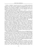
ZF introduced at about the same time their mechanically driven Turmat
centrifugal compressor for engines up to about 3.5 litres swept volume.
Relative to the turbocharger, it has the advantage of the absence of a hot and
costly turbine. On the other hand, it is certainly no simpler, since it has a
Variator V-belt drive (operating on the principle of the Van Doorne transmission,
Section 26.12, which is driven from the crankshaft, either directly or through
gears, Fig. 16.28.
The Variator, the ratio of which can be varied between about 1 : 2 and
1 :1.108, drives a 1 :15 ratio planetary gear system which, in turn drives the
centrifugal compressor. An optional feature is a clutch interposed between
the Variator and the planetary gear system. The transmission ratio of the
Variator is controlled automatically by a flyweight actuated mechanism,
which draws the flanges of the secondary pulley closer together as the speed
increases and allows them to be forced apart by the V-belt as the speed
decreases. This control can be supplemented or supplanted by a pressure- or
depression-actuated control which similarly moves the flanges of the primary
pulley. An alternative is electronic control.
2
3
Fig. 16.27 The Ro-Charger has been developed under licence from Felix Wankel.
Turning in the same direction about different axes, the two rotors are geared together
in the ratio 3 : 2, inner : outer. During rotation, the lobe of the inner rotor in chamber 1
retreats, drawing air in while rotating past the inlet port. At the same time, the lobe in
chamber 3, is advancing to discharge compressed air into the delivery port. Next, the
lobe in chamber 2 discharges into the delivery port while that in chamber 3 is
inducting air
588 The Motor Vehicle
Compressor
Planetary
gear
Magnetic
clutch
Variator
secondary
pulley
Variator
primary
pulley
Air out
Air in
Fig. 16.28 The ZF Turmat supercharger comprises a centrifugal compressor driven by
a Variator infinitely variable pulley-type transmission and a step-up planetary gear set.
Its magnetic clutch is optional
16.27 The pressure-wave supercharger
The pressure-wave, or Comprex, supercharger has been developed by Brown
Boverie. Basically it takes energy, in form of pressure pulses, directly from
the exhaust gas, in contrast to the turbocharger, which does so mechanically.
Consequently, the losses are small and pressure ratios of up to 3 : 1 are said
to be attainable.
The principle is illustrated in Fig. 16.29. Energy interchange between the
exhaust and inlet gases occurs in a set of straight tubular cells of approximately
trapezoidal section within the drum B. These cells, the ends of which are
open, are arranged around and parallel to the shaft on which the drum rotates.
The shaft is driven by a belt from the crankshaft. Because the unit does not
have to compress the gas it absorbs no more than between 1 and 2% of the
power output of the engine. Moreover, with such a large number of cells, the
compression process is virtually continuous, so synchronisation of rotation
with that of the crankshaft is unnecessary.
The sequence of operations is as follows. During each revolution of the
drum, one end of each cell in turn passes the end of the exhaust passage A.
This allows the exhaust gas, at the pressure in that passage, to flow along the
cell, compressing the air that it already contains against the closed far end.
Further rotation opens a port at the latter end, which allows the air thus
compressed to flow into the inlet passage F, which is then closed again when
the cell passes it. Closure of the port reflects a pressure pulse back to the
other end, which is now open to the exhaust downpipe through E. Consequently,
the exhaust gas is discharged to atmosphere, at the same time generating a
suction wave which travels along the cell. When this reaches the opposite
end, the port to the inlet pipe D is open, so a fresh charge of air is drawn into
the cell, and the cycle begins again.
589Turbocharging and supercharging
A
E
B
D
F
Fig. 16.29 The Comprex pressure-wave
supercharger
With spark ignition engines, unless the Comprex machine is installed
upstream of the carburettor, the exhaust gases will come into direct contact
with the fuel–air mixture, so it is principally of value only for diesel engines.
Since the exhaust gas pressure pulses travel at the speed of sound the Comprex
machine has the advantage of virtually instantaneous response. Another
advantage is that it is equally effective over the whole of the useful operating
range of the engine. Moreover, since the energy utilised is taken from the
exhaust gas, significant fuel economy is obtainable. The timing can be arranged
to provide a degree of exhaust gas-recirculation during the valve overlap
period, and this is claimed to reduce emissions of NO
x
by between 20 and
30%.
590
Chapter 17
Fuels and their combustion
Because the needs of spark and compression ignition engines differ widely
we shall deal with them separately in this chapter, taking spark ignition
engines first. Petroleum, more widely termed crude oil, is found in natural
reservoirs underground. It is the fossilised remains of minute fauna, as opposed
to the flora matter, mainly trees, from which coal is derived. This crude oil
is distilled in what is called a fractionating tower, to separate out its many
constituents, or fractions, among which are those for blending into petrol.
These boil off at temperatures ranging from about 25 to 220°C, Fig. 17.1.
They comprise mainly organic compounds, among which three chemical
groups predominate.
One group is the alkanes, alternatively known as paraffins. Typical arrange-
ments of the straight-chain normal molecules characteristic of alkanes can
be seen from Fig. 17.2. The longer the chain, the heavier is the molecule and
the higher the boiling point of the liquid. Variants termed alkenes and alkynes,
under the generic name of olefins, can be produced from the alkanes by
cracking processes, Section 17.2. Their molecules are like those of the alkanes,
but with some of the hydrogen atoms removed.
Alternative arrangements of hydrocarbon molecules are possible, and are
called isomers. Of these, perhaps the most widely known is iso-octane. For
assessing the octane number of a fuel that is being tested, a mixture of iso-
octane, defined as having an octane number of 100, and normal- or n-heptane,
defined as having an octane number of zero, is employed. The octane number
is the percentage of iso-octane in a mixture which has precisely the same
tendency to detonate as the fuel being tested. Incidentally, heptane (C
7
H
16
)
has nine isomers. Note that the general formula for alkanes is C
n
H
nx+2
, where
n is the number of hydrogen atoms. The molecular arrangements of n-octane
and iso-octane are illustrated in Fig. 17.3.
Another of the three main groups referred to in the opening paragraph of
this chapter comprises the cyclo-alkanes, so called because of their ring-like
molecular structures. Their general formula is C
n
H
2n
. They are present mainly
as cyclo-pentane and cyclo-hexane, Fig. 17.4. An alternative name for these
products is naphthenes, not to be confused with naphtha, which is a rather
loose term for a mixture of the light hydrocarbons.
The third series, the aromatics, also have ring like structures but, as can
be seen from Fig. 17.5, the arrangement differs slightly in that each carbon
591Fuels and their combustion
220
200
180
160
140
120
100
80
60
40
20
0
Cleanliness
and lube oil
dilution
Cold
driveability
Cold
start
Hot fuel
handling
Temperature, °C
0 20 40 60 80 100
% volume evaporated (standard test)
Economy
Fig. 17.1 Ease of cold starting is dependent on the percentage of fuel evaporating
below 70°C; too high a percentage, however, can lead to vapour formation in the fuel
system when the engine is hot
Fig. 17.2 The two smallest and lightest alkane molecules are those of methane (top)
and ethane (bottom). Both are gases at atmospheric temperature
C
CC
H
H
H
H
H
H
H
H
H
H
592 The Motor Vehicle
H
CC
C
C
CCCC
H
CCCC CCC
H
H
H
HH H
HH
H
H
H
H
H
H
HH
H
H
H
H
HHH
H
H
H
H
H
H
H
HH
Fig. 17.3 Examples of the long chain heavier alkanes are iso-octane (top) and
n-octane (below)
C
C
C
C
C
C
CC
C
C
CC
C
Fig. 17.4 Molecules of methyl cyclo-pentane and ethyl cyclo-pentane. This is a
simplified diagram, in which only the carbon molecules are shown. Such
simplifications are often used and are justified because we can take it that, at least in
hydrocarbon fuels, each carbon atom has four arms to which either carbon or
hydrogen atoms must be attached
atom is associated with only one hydrogen atom. The aromatics have high
octane numbers and therefore have been blended into unleaded petrol for
improving octane numbers. Some of the heavier among these compounds are
suspected of being carcinogens, but this has not been actually proved.
17.1 Distillation and blending
As can be seen from Table. 17.1, the contents of crude oils from different oil
fields differ widely. The fractions condense out of the distillation tower
593Fuels and their combustion
C
C
C
H
H
H
H
H
C
H
C
C
Fig. 17.5 This is a molecule of an aromatic, C
6
H
6
benzene. The inner arms of the
carbon atoms are linked in pairs instead of to hydrogen atoms
Table 17.1 PERCENTAGE PRODUCTS BY WEIGHT IN CRUDE OIL FROM
VARIOUS SOURCES
N. Africa N. Sea Mid. East N. America S. America
Sulphur 0.1 0.3 2.5 1.0 5.5
Wax 3 9 6 7 2
Light gasoline, 0–70°C 8.9 5.8 4.7 2.4 0.1
Octane No. 73 76 72 75 70
Naphtha, 70–140°C 16.0 11.0 7.9 6.5 1.1
Kerosine,180–250°C 26.3 18.6 16.4 15.6 4.4
Diesel oil: 250–350°C 18.2 19.1 15.3 19.6 9.6
Cetane No. 55 53 58 45 30
Residue ≥ 350°C 27.5 36.2 47.2 47.9 76.9
progressively into a series of trays, one above the other in the tower, Fig.
17.6: the heaviest fuels (those having the lowest boiling point) condense into
the lowest and the others into each tray in turn, until the lightest come out
into the topmost tray. A gaseous residue, mainly propane with small quantities
of iso-butane and n-butane issues from the top, and the heavy residue, containing
mainly bitumen, is drawn off from the base of the tower.
For two main reasons the distilled fractions have to be refined and blended
to render them suitable for use as petrol. First, they may contain impurities
such as sulphur that have to be removed and, secondly, there may be high
proportions of some constituents and shortages of others needed for producing
594 The Motor Vehicle
Bitumen
Crude oil
Gas
Aviation spirit
Motor spirit
Kerosine, white
spirit, jet fuel
Diesel fuel
Heavy gas oil
Lube oil stock
Fig. 17.6 Diagram representing the distillation process. Heat is applied to the crude oil,
causing the vaporous constituents to rise to the top, whence the gaseous content is
taken away and, in some instances, cooled to separate out the very light constituents.
On the way up the tower, the various liquid fractions condense out into a series of trays
from each of which they are drawn off through pipes, as indicated, and then put through
various refining processes
fuels suitable for use in road vehicles. The finished product must comprise
an appropriate mix of light factions for cold starting, and heavier fractions
for normal operation. Blending is done also to provide fuels with the overall
properties required, including high octane number for petrol and high cetane
number for diesel fuels, Sections 17.5 and 17.16.
17.2 The principal refining processes
The principal refining processes for the production of fuels are thermal,
catalytic and hydrocracking, and catalytic reforming. There are many others,
such as alkylation, isomerisation and polymerisation, for producing high-
octane fuels, and the finishing processes such as caustic washing for removal
of certain chemical contaminants, the Merox sweetening and extraction
processes for the removal of others, and hydro-desulphurisation. However,
we do not have space here for going into details. For further information,
readers could consult the Automotive Fuels Handbook, by Owen and Coley,
published by the SAE.
The cracking processes convert heavy molecules into lighter ones, having
lower boiling points. Thermal cracking entails heating the heavy distillate to
between 450 and 550°C. Alkanes crack most easily, followed in turn by the
cyclo-alkanes and aromatics. This process is more suitable for producing
diesel fuel than petrol.
Hydrocracking entails the use of a catalyst and addition of hydrogen, at
pressures of about 170 to 180 bar and temperatures of 450°C. The output is
mainly olefins. The process, by reducing the ratio of carbon to hydrogen
atoms in the molecules, reduces boiling point and increases octane number,
though some low octane number constituents may also remain.
595Fuels and their combustion
Catalytic cracking calls for high temperatures and pressures, and therefore
costly equipment. However, it gives a much better yield of high octane fuels
than either thermal or hydrocracking.
Catalytic reforming is used for increasing the octane number of naphtha
(mixture of light hydrocarbons). During this process several entirely different
chemical changes occur. One is the removal of hydrogen from aromatics, to
convert them into cyclo-alkanes. A second is isomerisation of the straight-
chain molecules of alkanes to produce higher octane branched-chain molecules.
The third is dehydrocyclisation, in which alkanes are first cyclised, forming
naphthenes and then dehydrogenated to produce aromatics. Other processes
occur concurrently, including hydrocracking which forms smaller naphthenic
molecules, and dealkylation in which the branch chains of higher aromatics
are removed to form lower aromatics.
17.3 Properties required for petrol
Boiling points are a good indication of how easily the fuel will vaporise,
though of course some evaporation will occur at almost any temperature.
The more volatile the fuel, the easier will it be to start the engine from cold.
Because neither condensation in the manifold nor evaporation from a float
chamber presents a problem with engines equipped with port injection, these
can be run on fractions having relatively low boiling points. However, if the
lighter fractions are too volatile, vapour lock might be experienced when the
engine is hot, though this is more likely to be experienced with carburetted
engines having fuel-lift pumps installed relatively high under the bonnet. A
proportion of heavier, high-boiling-point fractions are necessary for operation
at normal and high temperatures, with good volatility in the middle range in
order that enrichment for cold running can be cut out as soon as possible
after starting. If it is not, droplets of low-volatility fractions may be drawn
into the cylinders, diluting and even washing away the lubricant, and burning
incompletely in the cold combustion chambers, leaving carbon deposits.
Calorific value is an important property, though the difference between
the various hydrocarbon, including petrol and diesel, fuels is not of much
significance. It becomes a serious factor, however, with alternatives such as
the alcohols and, even more so, the gaseous fuels. All the alternatives entail
penalties of either large fuel tanks or short ranges of operation. In fact, the
energy density of the conventional hydrocarbon fuels is so high that it has
few competitors that are economical and safe.
Latent heat of vaporisation is also of some significance. The higher it is
the greater will be the cooling effect as the fuel evaporates into the air. This
is an advantage with fuel injection, since the charge becomes denser, and
therefore its energy content higher, as it cools. On the other hand, it can be
a disadvantage for single-point injected or carburetted engines, because it
encourages ice formation in the throttle barrel which, as mentioned in Chapter
13, can even stop the engine.
Cleanliness and purity of the fuel is essential. If substances other than
hydrocarbons are present, a wide range of problems can arise. Both water
and solid impurities, for instance, can cause corrosion and block or reduce
the efficiency of carburettor jets and injector nozzles. Sulphur is present in
all crude oils and therefore has to be removed during the refining of the fuel,
otherwise it will not only cause corrosion but also reduce the effectiveness of
596 The Motor Vehicle
the catalytic converters in exhaust systems. Other substances may leave
deposits of ash in the combustion chambers after they have burnt.
Perhaps the most important property of a fuel for spark ignition engines
is its octane number. If too low, the fuel will burn explosively, instead of
progressively, in the combustion chambers, causing over-heating and mecha-
nical damage, especially to components the strengths of which have been
reduced by local high temperatures. Piston crowns, rings and exhaust valves
are the most vulnerable.
17.4 Fuel-performance requirements
Two combustion phenomena, which should not be confused with each other,
have to be avoided: one is pre-ignition and the other detonation. Pre-ignition
is the ignition of the charge before the spark has passed. It causes rough
running and, in extreme cases, can do damage to the engine. In most instances
it arises because the fuel-air mixture is ignited by incandescent particles of
carbon in the combustion chamber. On the other hand, it can also be initiated
by incandescence of inadequately cooled metal parts in the chamber: sharp
corners and thin sections are the most likely to over-heat.
Detonation, on the other hand, sometimes referred to as ‘knocking’ or
‘pinking’ because of its characteristic noise, is a spontaneous explosion,
instead of the normal progressive spread of the flame throughout the mixture.
In normal combustion, the flame initiated by the spark travels across the
chamber, heating and expanding the gases that it has consumed and therefore
compressing the so far unburned mixture in front of it. If the rising temperature
of the unburned gases, due to both their compression and radiation from the
flame front, exceeds that of spontaneous ignition, they explode before the
flame front reaches them.
There are two potential causes of detonation. One is a combustion chamber
in which the distance that the flame has to travel is unduly long. Ideally the
spark should occur in the centre of a spherical chamber. This, however, is
impracticable for two reasons. First, with a chamber comprising a hemispherical
roof complemented by a hemispherical depression in the piston, the com-
pression ratio would be too low. Secondly, a long-reach spark plug placing
the electrodes in the centre of such a chamber would overheat and give rise
to pre-ignition.
The other cause of detonation is the use of a fuel the octane number of
which is too low. Each engine will detonate when run on a fuel of a certain
octane number. This number differs slightly from engine to engine. The
octane number applicable to an individual engine is termed the co-operative
fuel research (CFR) octane number, Section 17.5.
Detonation can occur in two distinctly different circumstances. One, as
already implied, is the use of a fuel of too low an octane number. The second
is that, even with a fuel of reasonable octane number, a sudden opening of
the throttle will cause the pressure in the manifold to rise and the high-
boiling-point fractions to condense out on its walls. Those with the highest
boiling points tend to be the aromatics, which also have the highest octane
numbers, so the overall octane number of the fuel actually being burnt in the
combustion chambers suddenly drops. Thirdly, there is high-speed knock.
This occurs if the temperatures and pressures in the cylinder become too
high at speeds between that of maximum torque and maximum power output.
597Fuels and their combustion
It can be insidious because, under these conditions, the noise of detonation
may be masked by the loud mechanical and normal combustion noises in the
background. Consequently, the driver may be unaware of it until serious
mechanical damage has been done to the engine.
It is sometimes difficult to distinguish between the noises arising from
detonation and other causes. Two other such noises are wild ping and crankshaft
rumble. Wild ping is intermittent detonation triggered by incandescence in
the combustion chamber ahead of the flame front, under conditions in which
detonation would not otherwise occur. Crankshaft rumble is due to resonant
vibration of the crankshaft, usually in a bending mode, and it may even alter
the mode of rotation of the crankshaft in its bearings, by causing it to orbit
around within them. It can be originated by forces generated by either regular
combustion or detonation.
17.5 Octane number and anti-knock index
As previously indicated, the octane number is defined as the lowest percentage
of iso-octane mixed with n-heptane that detonates at the same compression
ratio as does the fuel under test. iso-Octane (C
8
H
18
) is taken as having an
octane number of 100 and n-heptane (C
7
H
16
) of zero.
Two different fuel octane numbers are in general use. One is the research
octane number (RON) and the other the motor octane number (MON). There
is also a third, applicable to the vehicle rather than the fuel, and this is
termed the road octane number (RON). Yet another indicator of fuel quality
is the anti-knock index (AKI), which is the average of the RON and MON.
This is a slightly more reliable indication of the detonation resistance of a
fuel.
The RON is established on a standard single-cylinder research engine
having an accurately adjustable compression ratio. It is therefore a good
basis for comparison of different fuels. However, because mixture distribution
is not involved, it differs, from the results obtained in the multi-cylinder
engines in road vehicles, which is why the MON was introduced. This is
based on the ASTM D2700 test, run with a representative multi-cylinder
engine. The RON of a fuel is significantly higher than the MON: indeed, a
typical automotive fuel may have an RON of 98 and a MON as low as 88.
There is also a third indicator of detonation resistance, which is termed
the CFR road octane number, the initials CFR standing for co-operative fuel
research. This is a criterion of the engine instead of the fuel. It is determined
for individual engines on a co-operative basis by the major national and
international oil companies, who test a number of cars of each model and
pool their results to produce a comprehensive set of data indicating the
quality of fuel needed to satisfy the needs in their markets. This work is
necessary because, owing to differences between fuel metering systems,
engine and manifold layouts and sizes, and fuel distribution between cylinders,
each type of engine tends to perform differently with a fuel of any given RON.
17.6 Boiling point, vapour lock and ice formation in
induction systems
Vapour lock occurs when pipes or fuel pumps become over-heated. The low
pressure both inside the pump and in the pipeline between it and the tank
598 The Motor Vehicle
reduces the boiling point of the fuel, so heat transmitted to these components
by, for example, the exhaust manifold causes it to vaporise. Because pumps
are designed to deliver liquids, they cannot cope with vapour; consequently,
the supply of fuel to the engine is interrupted, causing it, at best, to run
roughly and, at worst to stop.
Vapour lock is most likely to occur after the vehicle has stopped, especially
after a slow climb to the top of a steep hill in hot weather. In these circumstances,
both the forward speed of the vehicle and the rotational speed of the engine
are generally low, so also therefore are the rates of flow from both a
mechanically driven fan and the water pump, and the engine therefore over-
heats. This heat is then conducted out to the surrounding parts, such as the
carburettor, fuel pump and pipe lines, in which some or all of their contents
vaporise. Consequently, the fuel pump may cease to function efficiently, if at
all, and even vapour, instead of fuel, may be delivered to the carburettor float
chamber or injection system and, with a carburettor, the fuel may have
boiled out of the float chamber. In either event, the engine cannot be restarted.
Indeed, if ambient temperatures are high and the float chamber or a pipeline
unshielded from and is too close to the exhaust manifold, the engine may
even stop while the vehicle is ascending a long steep hill.
Fuel-lift pumps usually deliver the fuel over a weir which, when the
engine has been switched off, retains some fuel within the pump to keep it
primed ready for restarting. However, this helps only marginally if the suction
line is full of vapour, and a long time may elapse before the fuel vapour has
condensed and the engine can be started again. The process can be speeded
considerably by pouring cold water over the pump and suction line. Vapour
can be difficult to clear from fuel-injection equipment so, on modern cars,
fuel pumps are usually electrically driven and installed inside the fuel tank,
so that they do not have to overcome suction heads.
Ice formation in both carburettors and with single-point injection is due to
moisture in the atmosphere wetting throttle valves and barrels and freezing
on them. This happens because of a drop in temperature of these parts,
arising from the latent heat of vaporisation of the fuel. It tends to occur when
the ambient temperature is slightly above freezing point and the relative
humidity high. If the moisture is already frozen before it enters the air intake,
it is more likely to bounce past the throttle and on into the cylinders. In severe
cases, the engine can be stopped by this build up of ice. Subsequently, after
the ice has been melted by heat conducted from the surrounding hot parts,
the engine can be restarted.
17.7 Composition of fuel for spark ignition engines
In the early nineteen-twenties, the term ‘petrol’ was originally introduced as
a trade name by an English company, Carless, Capel and Leonard, which
still exists. The American term ‘gasoline’ is, however, beginning to gain
ground in the British motor industry. Other terms that have been used include
‘motor spirit’ and ‘petroleum spirit’, the latter perhaps being the most
appropriate for what is basically a complex mixture of distillate from petroleum
(crude oil).
Because the contents of crude oils differ widely according to the part of
the world from which they come, the major oil companies often have to
refine crude stocks from different geographical sources and blend the distillates
599Fuels and their combustion
to produce a petrol suitable for use in motor vehicles. The actual blend
depends also on the season in which it is to be used, and a fuel for a hot
country must of course be less volatile than one for use in a cold climate. A
typical leaded petrol for use in the UK would have a range of volatilities
similar to that in Table 17.2. With the introduction of unleaded petrols, there
has been a trend towards increasing the proportions of lighter fractions, most
of which have higher octane numbers. Such fuels might contain between 24
and 45% aromatics, and from zero up to 26% olefins. The balance would be
made up of naphthenes and alkane saturates.
Because benzene, an aromatic having a high octane number, has been said
to be a carcinogen, legal restrictions in some countries limit it to about 5%
by volume. In general, emissions regulations are now so stringent that most
can be satisfied only by fuel injection and closed-loop control. With injection,
fuel-delivery pressures are higher than with carburation, and of course there
is no evaporation from float chambers. All this has strengthened the trend
towards fuels with a higher proportion of light fractions and therefore providing
good cold starting.
17.8 Additives
Additives are substances introduced, in small proportions, into fuels to enhance
their performance or to offset the effects of certain undesirable properties. It
all started in the early nineteen-twenties when the demand for fuel was
expanding rapidly and could no longer be satisfied by straight distilled
hydrocarbons. Oil companies started to crack the heavier fractions, to break
down their molecules into lighter ones and thus increase the supply of petrol.
Cracked products of that time tended to be unstable, reacting with oxygen to
form gummy deposits causing problems such as blocked carburettor jets and
filters. Consequently the first additives were anti-oxidants.
Because of the impending increasingly strict legal requirements regarding
exhaust emissions and fuel economy, additive technology is now being taken
more seriously than hitherto. Even so, at the time of writing, only three oil
companies in the UK, handling no more than 30% of the fuel sold there, are
marketing additive fuels.
Table 17.2 PROPERTIES OF A TYPICAL PREMIUM GASOLINE
FUEL FOR THE UK
Property Summer Winter
Specific gravity 0.734 0.732
Octane No. 97 97
Reid vapour pressure, kN/m
2
13.5 7.7
Initial boiling point, °C34 30
10% fraction boils off at, °C55 51
25% 74.4 63.5
50% 104.8 92.8
75% 139.2 129.4
Final boiling point 184 185
600 The Motor Vehicle
17.9 Lead compounds
Also in the early 1920s, Midgley, in the USA, discovered that adding tetraethyl
lead, Pb(C
2
H
5
)
4
, in small quantities to the fuel would inhibit detonation.
Subsequently it was found that compounds called scavengers, mainly 1,2-
dibromoethane and 1,2-dichloroethane, mixed with the lead, would prevent
it from forming hard deposits in combustion chambers and on valve seats.
By 1930, mixed in at a rate of about 0.6 g/l, tetraethyl lead (TEL) was
widely used to increase octane number. Today, any engine that is not designed
for running on unleaded fuel will suffer rapid wear of its exhaust valve seats
with a fuel having less than about 0.3 g/l of TEL. The reason is that the
combustion process leaves a coating of lead bromide compounds on the seats
and these inhibit welding of the peaks of the surface texture of the seats to
those of their mating faces on the valves.
By about 1960, tetramethyl lead (TML) began to be used. This has a
lower boiling point than TEL, so it evaporates with the lighter fractions of
fuel and therefore is drawn preferentially together with them into the cylinders.
At one time it was not uncommon for a mixture of TEL and TML to be used
as an anti-knock compound. During combustion, the lead additives form a
cloud of metal oxide particles. These, because the lead molecules are heavy
and the oxides chemically active, interrupt the chain-branching reactions
that lead to detonation. Incidentally, sulphur in the fuel reduces the effectiveness
of lead additives.
By the 1950s, huge resources were being poured by interested parties into
research to prove that burning lead additives in fuel produces toxic exhaust
fumes. True, in large concentrations over extended periods, it can adversely
affect brain development but, so far, no one has proved it can do so in the
concentrations that enter the atmosphere from automotive exhausts, even if
deposited on food crops. The reason for the abandonment of lead additives
has been that they adversely affect the performance of the catalysts in the
converters incorporated in vehicle exhaust systems. Lead additives, though
obsolescent, remain the most economical way of increasing octane number.
17.10 Lead-free fuels
One way of producing satisfactory lead-free fuels is to use oxygenate additives,
either alcohols or ethers, though these are costly. Alcohols include ethanol,
methanol, tertiary butyl alcohol (TBA), methyl tertiary butyl ether (MTBE),
tertiary amyl methyl ether (TAME) and ethyl tertiary butyl ether (ETBE).
Their octane numbers range from 104 to 136, and the octane numbers of the
fuels in which they have been blended range from 111 to 123. Even so, they
have tended to fall out of favour because, under certain conditions, they
break down and form hydroperoxides, which are corrosive and, combined
with other substances in the fuel, can produce other corrosive compounds.
Mathanol contains 49.9% oxygen, but MTBE and TAME contain only 18.2
and 15.7% respectively. The ethers, whose oxygen contents are lower than
those of the alcohols, are nevertheless an attractive alternative.
A widely used method of producing high-octane hydrocarbon fuel is to
isomerise the distillate to form mostly light, high-octane derivatives. Such
processing, however, is not only costly but also consumes energy that has to
be taken from the oil being processed. It therefore increases emissions of
601Fuels and their combustion
CO
2
, NO
x
and SO
2
into the atmosphere. Moreover, there is a limit to the
proportions of light components that can be blended into a motor fuel.
17.11 Detergent additives
Detergents were introduced initially in the early 1960s, in response to
driveability problems arising from the formation of deposits in carburettors.
‘Driveability’ is a term used mainly for describing the smoothness of the
response of the engine to movements of the accelerator pedal.
By the late 1960s and early 1970s, the introduction first of positive crankcase
ventilation and then exhaust gas recirculation led to the appearance of deposits
in all the passages from air filter to inlet valves and even on the valves
themselves. Again, the result was poor driveability. Consequently, it became
necessary to develop detergents that would be effective not only in the
carburettor but also throughout the system. Shell, with its ASD (Additive
Super Detergent) fuel, was first in the field, in the late 1960s and early 1970s,
and was using these second generation detergents in higher concentrations
than hitherto. A significant new feature was the use of carrier fluids, mainly
mineral oils, or polymers such as polybutene or polyetheramine, to take the
additives right through the induction system.
With both carburettors and throttle body injection, deposits are particularly
likely to be formed on hot spots in the induction manifold and any other area
in which heat soak increases local temperatures after the engine has stopped.
The oily additives partially or completely dissolve these deposits, which are
subsequently swept away and burnt in the combustion chambers. Too high a
content of such additives, however, can cause valve sticking and increase
combustion-chamber deposits, leading to higher octane requirements.
From approximately 1970 to 1980, induction-system temperatures increased
significantly, partly as a result of induction air heating and the other measures
for overcoming emissions problems. The situation was exacerbated by the
trends towards use of leaner air : fuel ratios and higher temperatures, for
improving thermal efficiency and hence fuel economy. An outcome was that,
because problems such as injector nozzle fouling arose as a result of heat
soak, oily additives became no longer adequate alone and therefore detergents
had to be used with them. However, the high temperatures involved called
for a different type of detergent additive, so polymeric dispersants and amine
detergents were then introduced.
In general, detergent additive molecules comprise an oleofilic chain-like
tail with a polar-type head, Fig. 17.7. The free arms of the head attach to the
particulate deposit and carry it away in the liquid fuel in which these detergent
molecules are dissolved.
17.12 Corrosion inhibitors
These additives are particularly desirable with injection systems since, without
them, malfunction will be caused by corrosion debris blocking the fine filters
used and the injector nozzles. Corrosion can also cause fuel tanks to leak,
even though they are protected internally by a corrosion-resistant coating.
Most corrosion inhibitors react with the acids that form in the fuels and
some, like the detergents, have polar heads and oleofilic tails, but the heads
latch on to the molecules of the metal surfaces, over which their tails form
a protective coating.
602 The Motor Vehicle
The fuel itself can also oxidise, causing the formation of gums that can
lead to difficulties both in storage and in the engine. Fuels containing high
proportions of cracked products are, as previously mentioned, particularly
susceptible to gum formation. Additives inhibiting the oxidation of the fuel
are therefore used, but mainly in storage.
17.13 Spark-aider additives
To satisfy emission control regulations, engines have to be operated on weak
mixtures, so good driveability can be difficult to achieve. As has been indicated
previously, cleanliness can help, but more important are the rapidity with
which the engine warms up and the consistency, from cycle to cycle, with
which the flame develops and spreads through the combustion chamber.
If the flame kernel around the spark does not expand rapidly to a certain
critical size, either the mixture will subsequently burn inefficiently or the
flame will die. Even if the engine is cold, the nominally rich mixture supplied
can still be weak in the region of the spark plug. This is partly because, on
the way to the cylinder, the lighter fractions can condense out and be deposited
on cold metal surfaces.
Consistency of combustion can be improved by the use of spark-aider
additives. However, if they are used together with lead additives containing
halogen compounds, they could lead to sticking and deterioration of the inlet
valves. They function by coating the electrodes with a compound facilitating
the passage of the spark and thus allowing more energy to be applied to
ignite the mixture.
17.14 Diesel fuels
Whereas for the spark ignition engine the fuel and air are supplied pre-mixed
to the cylinders, in a diesel engine the fuel is not injected into the air until
shortly before TDC. Consequently, there is considerably less time for comple-
tion of the mixing and evaporation processes. Furthermore, the diesel engine,
having no throttle, is controlled by regulating the quantity of fuel injected
per induction stroke. Add to this the fact that ignition cannot occur until the
temperature generated by compression is high enough, and it becomes obvious
that fuel quality is even more important for the diesel than the spark ignition
engine.
Detergent
molecule
latched on
to carbon
particle
Carbon
particle
Free
detergent
molecule
Wall of manifold
Fig. 17.7 Showing how detergent additive molecules latch on to the dirt particles to
carry them away in solution
603Fuels and their combustion
Whereas in Europe there is one grade of diesel fuel for road vehicles, in
the USA there are two, ASTM D1 and D2. The European Union defines a
diesel fuel as containing a maximum of 65% distilled off at 250°C and a
minimum of 85% distilled off at 350°C. A UK diesel fuel might have the
following properties—
Specific gravity 0.85 Cloud point –5.5°C
Sulphur 0.22% Initial boiling point 180°C
Cetane No. 51 50% vaporisation 280°C
Cold filter plugging point –18°C Final boiling point 360°C
Hydrocracking and catalytic cracking are used to convert fractions having
even higher boiling points into hydrocarbons suitable for use as diesel fuels.
However, both hydrocracked and catalytically cracked fuels tend to have
cetane numbers, Section 17.16, in the region of only 10 to 30. Catalytically
cracked fuels, moreover, tend to be slightly unstable in storage.
17.15 Properties required for diesel fuel
A few of the properties required, such as high calorific value (energy content),
are common to both gasoline and diesel power units, but most are much
different. Diesel fuel mostly comprises fractions boiling off from approximate-
ly 150 to 355°C, Fig. 17.8, as compared with about 15 to 210°C for gasoline.
As delivered from the fractionating tower, these higher boiling point fractions
Final boiling point (FBP)
Mid boiling point (MBP)
Initial boiling point (IBP)
400
300
200
100
020406080100
Fraction, %
Temperature, °C
Fig. 17.8 This characteristic distillation curve for diesel fuel is similar in form to that
illustrated in Fig. 17.1, but of course the initial and final boiling points are higher
604 The Motor Vehicle
contain about 20 times more sulphur than those from which gasoline is
derived, so extra attention has to be devoted to removing it during refinement.
The following are the properties that must be controlled when diesel fuels
are blended—
Volatility High volatility helps with cold starting and obtaining
complete combustion.
Flashpoint The lower the flashpoint the greater is the safety in handling
and storage.
Cetane number This is a measure of ignitability. The higher the cetane
number the more complete is the combustion and the cleaner
the exhaust.
Viscosity Low viscosity leads to good atomisation.
Sulphur Low sulphur content means low wear and a smaller
particulate content in the exhaust.
Density The higher the density the greater is the energy content of
the fuel.
Waxing tendency Wax precipitation can render cold starting difficult and
subsequently stop the engine.
As in the case of petrol, properties of a diesel fuel depend in the first
instance on the source of the crude oil from which it is distilled. These vary
as follows—
UK and Norway Mainly paraffinic and therefore of high cetane
number. Calorific value relatively low and cloud
point high. Sulphur content low to medium.
Middle East Similar, but high sulphur content. Middle East crude
oils are a particularly good source for diesel fuel,
because they contain a high proportion of alkanes
and a small proportion of aromatics.
Nigeria Naphthenic. Low cetane number, cloud point and
sulphur content. Calorific value medium.
Venezuela and Mexico Naphthenic and aromatic. Low cloud point and very
low cetane number, but low to medium sulphur.
Calorific value high.
Each of the properties in the lists above influences engine performance,
so we need to study them in more detail.
17.16 Cetane number, cetane index and diesel index
Basically, the cetane number is the percentage of cetane in a mixture of
cetane (n-hexadecane) and heptamethylnonane (the latter is sometimes referred
to as α-methylnaphthalene) that has the same ignition delay, generally expressed
in terms of degrees of rotation of the crankshaft, as the fuel under test. There
is a more precise definition but, before we come to it, a brief note on ignition
delay is necessary.
Ignition delay, Section 17.32, is important because, if it is too long, the
605Fuels and their combustion
whole charge in the cylinder tends to fire simultaneously, causing violent
combustion. With a short delay, ignition is initiated at several points, and the
flame subsequently spreads progressively throughout the charge. On the
other hand, the injection must be timed appropriately relative to the cetane
number of the fuel that will be used: a higher cetane number than that for
which the timing was set can lead to ignition before adequate mixing has
occurred and thus increase emissions.
Cetane number is defined precisely as the percentage of n-cetane + 0.15
times the percentage of heptamethylnonane contents of the blend of reference
fuel having the same ignition quality as the fuel under test. Ignition quality
is determined by varying the compression ratio to give the same ignition
delay period for the test fuel and two blends of reference fuels. One blend
has to be of better and the other of poorer ignition quality than the test fuel,
but the difference between the two has to be no more than five cetane numbers.
The cetane number is obtained by interpolation between the results obtained
at the highest and lowest compression ratios.
Carrying out these laboratory engine tests, however, is not at all convenient,
so two other criteria are widely used. One is the diesel index and the other
the cetane index. The diesel index, which is obtained mathematically, is
computed by multiplying the aniline point of the fuel by its API gravity/100.
The aniline point is the lowest temperature in degrees fahrenheit at which the
fuel is completely miscible with an equal volume of freshly distilled aniline,
which is phenylamine aminobenzene. API, measured with a hydrometer,
stands for American Petroleum Institution, and degrees API = (141.5/Specific
gravity at 60°F) – 131.5 It is a measure of density for liquids lighter than
water.
The cetane index is calculated from API gravity and volatility, the latter
originally taken as represented by its mid-volatility, or mid-boiling point
(50% recovery temperature, T
50
). Since its introduction, the formula has
been modified from time to time, to keep up with advancing fuel technology,
and is now based on an extremely complex formula embracing the density
and volatility of three fractions of the fuel (those at the 10, 50 and 90%
distillation temperatures T
10
, T
50
and T
90
, respectively). This formula can be
found in Automotive Fuels and Fuel Systems, Vol. 2, T.K. Garrett, Wiley.
The cetane index is, in general, better than the diesel index as an indication
of what the cetane number of a fuel would be if tested in a CFR engine in a
laboratory, and it is much less costly and time-consuming to obtain. In general,
alkanes have high, aromatics low, and naphthenes intermediate, cetane and
diesel indices.
Values of 50 or above for either the diesel or cetane index indicate good
combustion and ignition characteristics, below 40 are totally unacceptable
and even below 45 undesirable. Low values mean difficult cold starting the
generation of white smoke, and the engine will be noisy.
BS 2869: Part 1: 1988 prescribes minimum limits of 48 for the cetane
number and 46 for the cetane index. In Europe and Japan the minimum
cetane number requirement is 45, and in the USA it is 40, the latter possibly
being because a high proportion of their crude oil comes from Mexico and
Venezuela. A reduction in cetane number from 50 to 40 leads to an increase
in the ignition delay period of about 2° crankshaft angle in a direct and about
half that angle in an indirect injection engine.
606 The Motor Vehicle
17.17 Tendency to deposit wax
In cold weather, a surprisingly small wax content, even as little as 2%, can
crystallise out and partially gel a fuel. These crystals can block the fuel
filters interposed between the tank and injection equipment of the engine,
and ultimately cause the engine to stall. In very severe conditions, the pipelines
can become blocked and a thick layer of wax may sink to the bottom of the
fuel tank. Paraffins are the most likely constituents to deposit wax which,
because they have high cetane numbers, is unfortunate.
The various measures of the tendency of a fuel to precipitate wax include
cloud point, which is the temperature at which the wax, coming out of
solution, first becomes visible as the fuel is cooled (ASTM test D 2500).
Another test (ASTM 3117) is for the wax appearance point, which is that at
which the wax crystals become visible in a swirling sample of fuel.
Then there is the pour point, which is the temperature at which the quantity
of wax in the fuel is such as to cause it to begin to gel (ASTM D97). To
establish the pour point, checks on the condition of the fuel are made a 3°C
intervals by removing the test vessel from the cooling bath and tilting it to
see if the fuel flows. Another criterion, the gel point, is that at which the fuel
will not flow out when the vessel is held horizontal. In practical terms, this
translates roughly into a temperature 3° above that at which it becomes no
longer possible to pour the fuel out of a test tube.
Another way of estimating operational performance of a fuel is to combine
the cloud point, CP, and the difference between it and the pour point, PP, to
obtain a wax precipitation index, WPI. The formula for doing this is as
follows—
WPI = CP – 1.3(CP – PP – 1.1)
1
2
Other tests include the cold filter plugging point (CFPP) of distillate fuels,
IP 309/80 and the CEN European Standard EN116: 1981. This the lowest
temperature at which 20 ml of the fuel will pass through a 45 µm fine wire-
mesh screen in less than 60 s. However, since paper element filters are now
widely used, the relevance of wire-mesh filters is open to question so, at the
time of writing, the CEN is debating the desirability of introducing a test
called the simulated filter plugging point. In the USA, the low temperature
fuel test (LTFT) is preferred to the CEPP test. The LTFT is the temperature
at which 180 ml of fuel passes through a 17 µm screen in less than 60 s. All
these and other tests are described in detail in Automotive Fuels and Fuel
Systems, Vol. 2, T.K. Garrett, Wiley.
17.18 Density
Because injection equipment meters the fuel on a volume basis, any variations
in density, because it is related to energy content, will affect the power
output. The greater the density of the fuel the higher will be both the power
and smoke. Fortunately, however, hydrocarbon fuels differ relatively little as
regards their densities.
Density is measured by the use of a hydrometer with scales indicating
specific gravity or g/m
3
. The sample should be tested at 15°C or the appropriate
correction applied. Figures for density differ from those for API gravity, or
deg API, in that the higher the number in deg API gravity, the lighter is the
fuel.
607Fuels and their combustion
17.19 Volatility
The volatility of the fuel influences many other properties, including density,
auto-ignition temperature, flashpoint, viscosity and cetane number. Obviously,
the higher the volatility the more easily does the fuel vaporise in the combustion
chamber. Low-volatility components may not burn completely and therefore
could leave deposits and increase smoke. Within the range 350 to 400°C,
however, the effects of low volatility on exhaust emissions are relatively
small. The mix of volatilities is important: high-volatility components at the
lower end of the curve in Fig. 17.8 improve cold starting and warm-up while,
at the upper end components having volatilities that are too low increase
deposits, smoke and wear.
17.20 Viscosity
The unit of kinematic viscosity is the stoke, which is the time taken for a
certain volume of fuel at a prescribed temperature and a constant head to
flow under the influence of gravity through a capillary tube of a prescribed
diameter. That of absolute velocity is the poise, which is the force required
to move an area of 1 cm
2
at a speed of 1 cm/s past two parallel surfaces that
are separated by the fluid. For convenience, the figures are usually expressed
in centipoises and centistokes (cP and cSt). The two are related in that cP =
cSt × Density of the fluid. The SI units are m
2
/s, and the CGS or stoke’s units
are cm
2
/s (see also Section 18.4).
Increasing viscosity reduces the cone angle of the injected spray and the
distribution and penetration of the fuel, while increasing the size of the
droplets. It will therefore affect optimum injection timing. An upper limit for
viscosity has to be specified to ensure adequate fuel flow for cold starting.
Lucas Diesel Systems quote a figure of 48 cSt at –20°C as the upper and, to
guard against loss of power at high temperatures, 1.6 cSt at 70°C as the
lower limit. BS 2869 calls for a maximum value of 5 cSt and a minimum of
2.5 cSt at 40°C. In Fig. 17.9, all these points are plotted and a viscosity
tolerance band established. The viscosity of the average fuel lies approximately
mid-way between the upper and lower limits.
Too high a viscosity can cause excessive heat generation in the injection
equipment, owing to viscous shear in the clearances between the pump plungers
and their bores. On the other hand, if it is too low, the leakage through those
clearances, especially at low speeds, can be so high that restarting a hot
engine can become impossible. This, however, is because the increase in
temperature of the fuel locally due to conduction of heat to the injection
system during a short shut-down period further reduces the viscosity of the
fuel in the pump prior to starting.
17.21 Smoke
When the engine is started from cold, white smoke comprising tiny droplets
of liquid, mainly fuel and water, increases as cetane number and volatility of
the fuel are reduced. It persists until the temperature has risen to the point at
which the droplets are vaporised in the engine and remain so until well after
they have issued from the exhaust tail pipe. The reason why the fuel droplets,
although surrounded in the combustion chamber by excess oxygen, remain
608 The Motor Vehicle
unburnt is that, in the cold environment, not only do they not evaporate but
also their temperature never rises to that of auto-ignition.
Cetane number increases with the density and volatility, and varies with
composition of the fuel. Fuels having high cetane numbers are principally
the paraffinic straight-run distillates. However, because these have both high
cloud points and low volatility, a compromise has to be struck between good
ignition quality and suitability for cold weather operation.
Another product of combustion can be black smoke. This is formed because
the hydrogen molecules are oxidised preferentially so, if there is insufficient
oxygen in their vicinity, it is the carbon atoms that remain unburnt. High aromatic
content, viscosity and density and low volatility all increase the tendency to
produce black smoke.
Although aromatics tend to produce smoke, they also make a major
contribution to the lubricity of the fuel. Consequently, their removal can give
rise to abnormally high rates of wear of injection pumps, especially in
distributor-type pumps in which all the work is done by only one or two
plungers and, perhaps, a single delivery passage might be subject to severe
erosion.
As previously explained, the volatility factor is misleading. Because the
more volatile fuels have high API gravities (indicating low specific gravities),
and their low viscosities allow more to escape back past the injection pumping
elements, the weight delivered to the cylinder per injection is smaller. For
any given power, a certain weight of fuel must be injected, so a greater
volume of the more volatile fuel and a longer injection period are therefore
48.0
5.0
2.5
1.6
Temperature of fuel, °C
Kinematic viscosity of fuel, cSt
40
20
10
4
2
–20 –10 0 10 20 30 40 50 60 70
Fig. 17.9 A typical tolerance band for fuel viscosity is illustrated here. At 40°C, the
limits are from 2.5 to 5.0 cSt