The Motor Vehicle 2010 Part 5 potx
Bạn đang xem bản rút gọn của tài liệu. Xem và tải ngay bản đầy đủ của tài liệu tại đây (2.77 MB, 70 trang )
304 The Motor Vehicle
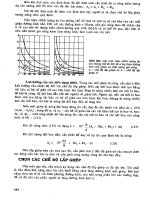
Fig. 7.64 Left, with rising fuel pressure due to increasing speed, the piston is
progressively moved to the right, advancing the ignition. Right, as speed and therefore
fuel pressure fall, the piston is moved to the left by its return spring
regulated by the ECU, and its function is to modify the basic, or speed
dependent, timing in relation to engine load and temperature.
7.32 Stanadyne rotary distributor pumps
The forerunner of all the pumps of this type so far described was the invention
sold in 1947 to the Hartford Division of Stanadyne by Vernon Roosa. Two
features distinguished this invention: one was the substitution of two opposed
plungers for the then universal arrangement of one plunger for each engine
cylinder; the other was the use of inlet, instead of spill, metering. The latter
feature meant that the unit was almost self-governing, so that only a simple
low cost governor was needed. By virtue of its compactness and simplicity,
this pump could be produced at a much lower cost than the in-line pumps.
After 5 years of development, the Roosa Master Model A pump, with
mechanical governing, was put in production. In 1952, it was supplied to the
Hercules Motors Corporation, for fitting to the Oliver Cletrac tractors. Between
1955 and 1958, the Model B and D pumps were introduced and, in 1958, the
Model DB replaced the A and D units. In 1972, the DM, with a heavier
section rotor and four plungers, was introduced.
The DB2, a second generation DB pump, was first produced in 1972. As
can be seen from Figs 7.65 and 7.66, it is similar to the Lucas DP Series,
Section 7.1, originally produced under licence from Stanadyne, but the
differences are of considerable interest. The two- and all-speed governors,
Sections 7.8 and 7.12, differ only in detail. On the two-speed version, however,
provision is made for fuel temperature compensation. The rate of change of
fuel flow per 10°C change in temperature is about 0.9% by weight and 1.8%
by volume.
Temperature compensation is especially desirable if the pump is mounted
between the banks of engines of the V layout, where it can become very hot.
Idling speed decreases with increase in fuel temperature, and adjustment for
305 Distributor type pumps
Fig. 7.65 The Stanadyne DB2 pump with a solenoid-actuated mechanism in the top
cover, for key start and stop operation
Transfer pump
Automatic
advance
Governor
spring
Governor
Mech. fuel
Charging
annulus
Housing
press. reg.
Plungers
Rotor
Delivery
valve
Head
passage
Return to tank
Metering valve
Main
filter
Fuel pressure
regulator
Nozzle
Injection pressure circuit
Fuel supply housing bypass
and return circuits
pressure circuit
Separator
compensation
device
Fuel
tank
Lift
pump
Vent wire
shut-off
To injectors
Transfer pump
Viscosity
Fig. 7.66 Schematic diagram of the Stanadyne DB2 system
306 The Motor Vehicle
increasing the idling speed to prevent stalling may be impracticable in vehicles
with automatic transmission. The solution is to mount a bimetal strip in
series with the idling spring, Fig. 7.67. This bimetal strip is biased in a
manner such that, as the temperature of the fuel in the pump rises, the open
area of the fuel metering valve increases.
An entirely different thermal problem can arise during rapid acceleration
at low temperatures. The shearing of the oil film in the distributor head
generates a considerable amount of heat and the mass of distributor shaft is
less than that of the sleeve in which it rotates. In these circumstances, this
shaft can become significantly hotter and therefore expand more rapidly,
closing the clearance between it and the sleeve. This can cause seizure.
Stanadyne have found that this problem can be overcome by machining a
peripheral groove midway between the ends of the bearing surfaces, which
is the region that becomes hottest. The rotor is similar to that in Fig. 7.21, but
there are no grooves in the ends of the maximum fuel adjustment plates,
which Stanadyne call leaf springs.
The arrangement of the fuel delivery ducting in the rotor differs from that
of the Lucas pumps. Passing axially along to the end of the rotor, which is
counterbored to house a delivery valve Fig 7.68, is the high pressure delivery
duct from the plungers. From this illustration, it can be seen that a duct is drilled
from the periphery of the rotor into the chamber that houses the delivery
valve return spring. During rotation, it is aligned in turn with each
Throttle
shaft
+ Fuel
Idle spring
Bi-metallic element
+ –
Fuel
Effect of fuel temperature
on idle speed
Engine speed–(rpm)
700
600
500
Compensated
Uncompensated
Fig. 7.67 Above, the mechanism
for temperature compensation of
engine idling speed. Below, the
100 120 140 160 180 200
effect of temperature
Fuel temperature (°F)
compensation
307 Distributor type pumps
h
Fig. 7.68 This delivery valve is housed in a
counterbore in the end of the distributor rotor
of the ports leading to the injectors. As the delivery valve returns to its seat,
following injection, its end remote from the seat enters the bore in which the
valve slides and withdraws with it some of the fuel from the delivery line.
This generates a negative pressure wave, which rebounds along the delivery
line to each injector, to prevent secondary injection or dribbling.
If the retraction volume is large, vapour-filled cavities can form just
downstream of the delivery valve. This can be avoided by installing a snubber
valve, Fig. 7.69, in each pipe connection. The snubber is a plate type valve
with a hole through its centre, to damp reflected pressure waves. Its effect,
therefore, is to enable a smaller retraction volume to be specified for the
delivery valve.
The injection timing advance mechanism is similar to those previously
described. Its maximum advance for eight-cylinder engines is 10° of pump
shaft rotation and for the others 12°. If, however, the fuel delivery volume is
Fig. 7.69 On the DB2 pump, snubber valves are installed in the pipe connections to
the cylinders. The small axial hole through the valve damps reflected waves, to reduce
the potential for cavitation erosion
308 The Motor Vehicle
less than 30 mm
3
per stroke, the advance may be increased by 1° or 2°. A
servo-controlled advance is also available. This advance compensates for
two effects: the ignition delay period and the time taken for the pressure
wave to travel from the pump plungers to the injectors. The formula used to
calculate the advance needed is:
(Cam advance = LN 2 – N1)
16 800
where L = length of delivery line, inches
N2 = rated speed
N1 = minimum full load speed.
This formula is based on the assumptions that there are no vapour cavities in
the line and that the wave speed is 4200 ft/s or 1280.16 m/s. If metric units
are used throughout, the constant 16 800 becomes 130.064.
7.33 Stanadyne DS electronically controlled pump
This pump, introduced in 1993, is similar mechanically to the DB2 unit, but
without the governor. It is capable of delivering 75 mm
3
per stroke at 1200
bar at the injectors of four-cylinder engines. A high capacity belt drive can
be employed if required.
The quantity of fuel delivered to the four plunger is regulated by an
electronically controlled poppet type spill valve. A stepper motor actuates
the cam-ring advance mechanism. With these arrangements, both the timing
and quantity of fuel injected are accurately regulated in relation to load,
speed and other engine parameters, while keeping to a minimum, under all
conditions of operation, emissions of HC, CO, NO
x
and smoke. Accuracy of
control is further assured by housing the cam rollers and tappets in the large
diameter drive shaft with zero backlash. Thus the distributor is isolated from
the drive, and therefore isolated from torsional oscillations that might lead to
inaccuracies in the timing.
The layout of the pump can be seen in Fig. 7.70. A commendable feature,
and unique at the time of its introduction, is the housing of the spill valve
coaxially in a counterbore in the end of the rotor. With this arrangement, the
volume of fuel subjected to injection pressures is very small, so there is less
risk of compressibility causing the injection characteristics to depart from
those dictated by the profile of the cam geometry.
Situated at the top of the unit, the fuel inlet is readily accessible, even on
V engines. Other advantages claimed by Stanadyne are as follows. A heavy
duty drive, and flexibility in respect of the all of the following: governing,
idle speed and cold running control, fuel metering and timing control on a
shot-to-shot basis.
Fig. 7.71 illustrates the control system. Pump speed, angular pulse train
data and data based on signals from the engine-mounted sensors are
continuously updated by the electronic control module (ECM). They are
processed by custom algorithms, and the resultant command signals are sent
to the pump-mounted solenoid driver (PMD) and cam-ring advance stepper
motor.
Because a single, high speed solenoid is used for the control functions,
the benefits of ease, flexibility and accuracy of signal processing associated
309Distributor type pumps
Discharge fitting
Pump housing
Solenoid
Poppet valve
Advance
Cam
Electric shut-off (ESO)
Needle
bearing
From electronic
control module
(ECM)
Optical sensor timing
encoder (OSTE)
From pump
mounted driver
Advance stepper
motor
Drive
shaft
Fig. 7.70 The Stanadyne DS electronically controlled pump was introduced late in
1993
Coolant temperature
Crankshaft reference
Throttle sensor
Closure
ECM
Memory
Processor
network
Switched inputs
Outputs
Spare
Warning
lamp
Inject
EGR
Start
aids
Communications
Diagnostics
Starting
aids
EGR
control
DS
pump
Pump
mounted
driver
Lamp
Fuel
Temperature
OSTE
pump speed and
reference
Fig. 7.71 Schematic diagram of the DS electronic control system
with digital control have been obtained. Fuel metering and timing are regulated
as a function of the input data to the ECM, which controls the PMD. The
latter supplies the injection command signals and a constant current. Closure
of the poppet type spill valve is detected by the PMD and signalled back to
the ECM. The timing and quantity of fuel needed for each injection are
updated on a shot-to-shot basis, so the engine response to changes in load is
virtually instantaneous.
Fuel transfer pump
Distributor
rotor
Manifold pressure
Intake air temperature
Start of injection
optional
310 The Motor Vehicle
As the control strategy is angle, instead of time, based, the performance
of the system is outstandingly good. This follows from the fact that the
requirements for both metering and timing are functions of crankshaft angle.
The outcome is good performance under transient conditions.
An encoder on the pump drive shaft serves as a high resolution clock. Its
performance is enhanced by a phase lock loop (PLL) circuit in the ECM,
which gives a resolution of 0.04
°. Control over the metering and timing events
is exercised, by a series of digital counters in the ECM, on the basis of signals
received from the angular clock.
Fig 7.72
Chapter 8
Some representative
diesel engines
Presented in this chapter are some examples of what have been and, in some
instances still are, outstanding diesel engine designs. The Perkins three-
cylinder indirect injection engine, for example, has found many applications
including in some of the earliest diesel cars produced in small numbers and,
of course, light commercial vehicles. Designed and produced by the same
company, initially in association with Austin-Rover for installation in some
of their cars and Freight Rover vehicles, the Prima was the first of the 2.5
litre direct injection engines. The Gardner LW is a classic heavy diesel
engine, while the Cummins 10 litre engine is a modern design in which unit
injection is employed.
8.1 Perkins P3 diesel engine
This engine was developed for installation in or as a conversion unit for light
commercial vehicles and tractors. Its attraction was the flat torque characteristic
and fuel economy of the diesel engine. Prior to this, diesel engines were
ruled out for this type of vehicle because of the difficulties associated with
the design of injection equipment for them and obtaining satisfactory
combustion characteristics in small cylinders. The solution to the problem
then appeared to be reducing the numbers of cylinders.
Perkins were able to rationalise production and the supply of spare parts
by basing the P3 three-cylinder engine on the P4 and P6, four- and six-
cylinder units. In fact, the P3 was basically half of the P6 engine. The only
new parts required where those related to the length of the unit, principally
the crankshaft, cylinder block and sump. With only three cylinders, the unit
was of convenient size for substitution for an alternative petrol engine.
Longitudinal and cross-sectional views of the engine are shown in Fig.
8.1, from which the sturdy and yet compact design will be noted. Dry cylinder
liners are fitted into a nickel or chromium cast iron block which extends
from the head face to the crankshaft centre line in the conventional manner.
The bore and stroke are 89.9 and 127 mm respectively and the connecting
rods are 228.6 mm long between centres. A sturdy four-bearing crankshaft,
with Tocco hardened journals, is employed.
311
312 The Motor Vehicle
Fig. 8.1 Perkins P3 engine
Some representative diesel engines 313
With three cranks at 120° pitch there are no primary or secondary unbalanced
reciprocating forces, and the rotating couple is balanced by the two attached
balance weights on the end crank webs. Primary and secondary couples
remain to be absorbed by the engine mounting, and this disadvantage and the
massive flywheel required to absorb the variations in turning moment are the
penalties to be paid for the convenience of the three-cylinder lay-out.
8.2 Perkins Prima DI engine
The alternative to reducing the number is, of course, to reduce the size of the
cylinders. This had, until 1986, been impracticable for the reasons given in
Section 6.12. Though, as mentioned previously, Perkins was first with its
Prima engine, Ford had about a year earlier introduced a 2.5-litre DI diesel
engine rated at 4000 rev/min for their Transit van. Some of the disadvantages
of indirect injection are outlined in Section 6.12 and the problems to which
it is a solution in Section 6.18.
As can be seen from Fig. 8.2, the Prima is a four-cylinder unit with an
enclosed, 30 mm wide, HTD toothed belt drive from the crankshaft to the
injection pump and overhead camshaft. The alternator on the side of the
crankcase, and the spindle of the fan and water pump above the crankshaft,
are both driven by a V-belt from a pulley on the front end of the crankshaft.
On the other hand, the oil pump is interposed between the toothed wheel for
the HTD drive and the crankcase wall and driven by a gear on the crankshaft.
It is of interest that, unlike the Prima, the larger and more powerful Phaser
engine has an all-gear drive for its auxiliaries, Sections 6.16 and 6.17. On the
Prima, a toothed belt is more suitable because it is lighter yet adequate for
the loading and, particularly important for a car engine, quieter. Another
factor that may have influenced by choice is the fact that the crankcase was
designed to be machined by Austin-Rover on the same production line as the
O-Series petrol engine described in Section 3.65, which also has a toothed
belt drive.
Structurally, the engine is similar to the O-Series, with siamesed cylinders
and a fully balanced SG iron crankshaft carried in five main bearings. However,
whilst the crankcase, because of the need for good bearing properties in the
cylinder bores, is of the same high quality, flake graphite cast iron as that of
the O-Series, the main bearing caps are of the stronger SG iron to react to the
higher peak gas pressures of the diesel engine. In the turbocharged version,
peak combustion pressure is of the order of 12 000 kN/m
2
.
One of the advantages of DI head, as compared with one for an IDI
engine, is the freedom to position generous coolant passages all round the
valve seats, owing to the absence of a pre-chamber, and the consequent
reduction in thermal fatigue loading. The eight valves are in line, with their
axes in a vertical plane slightly offset to one side of that containing the axis
of the crankshaft, so that the injector nozzles, on the other side, can be sited
appropriately relative to the bowl type combustion chambers in the pistons.
Sintered iron valve seats are shrunk into the head.
The pistons have steel inserts for expansion control. They are of the three-
ring type, the top ring being armoured, which means that its groove is machined
in a steel ring bonded in the periphery of the piston, the appropriate distance
below its crown. Armoured ring grooves, which are a useful aid to reducing
the rate of wear of the very hot top grooves, especially in the more severely
314 The Motor Vehicle
Fig. 8.2 Longitudinal and transverse sections of the Perkins Prima 2-litre direct injection diesel engine
315 Some representative diesel engines
loaded turbocharged engines, are uncommon in light diesel engines for cars.
The turbocharged engine also has jets in the main gallery to squirt oil up into
the pistons to help cool them. Centrally positioned in the piston crowns are
shallow cylindrical combustion chambers. These have flat bases around which
are fillets of large radii to merge them smoothly with their vertical walls.
Small lips inside the upper edges of these walls trigger micro-turbulence in
the air as the squish spills over them into the chambers below.
The chilled cast iron camshaft is carried in three bearings, the upper
halves of which are formed in the cast aluminium alloy cover and the lower
halves in the head casting which, by virtue of the absence of the need to core
in it a pre-chamber capable of resisting very high temperatures, is also of
aluminium alloy. Single springs for each valve are enshrouded by inverted
bucket type steel tappets, discs of appropriate thicknesses being used for
setting the valve clearance. Two concentric springs would have been
unnecessary for this engine because its valve train is of relatively light weight
compared with those of the heavier engines for commercial vehicles.
High volumetric efficiency was obtained by curving the inlet ports to give
the air an initial swirl before directing it tangentially into the cylinders,
instead of masking the valves, or restricting their throats to increase the
velocity of flow. Then, as the piston rises to TDC, micro-turbulence is
introduced, as described above. This system was found to be much more
appropriate to such a small engine than any of those of the larger, slower
speed diesel engines, many of which have combustion chambers of part
spherical, or even toroidal, form to introduce a secondary swirl, as distinct
from micro-turbulence, into the primary one.
As regards fuel supply, a prime requirement was to shorten the ignition
delay period. This was necessary in order that injection could be retarded, to
limit the length of time during which the combustion products dwell in the
very high temperature range, thus reducing emissions of NO
x
yet still enabling
the engine to operate efficiently over a speed range adequate for a private car
installation. In the event, it was found that injection at 10° before top dead
centre was the optimum at the maximum speed of 4500 rev/min. As the
speed of the engine falls, it is automatically retarded further, because there
is then more time in which to complete combustion before the exhaust valve
opens. The relationship between engine speed and injection retard, however,
is not linear.
The next problem was intimate mixing with the air to ensure that all the
fuel would be completely burned without leaving black smoke or other
undesirable emissions in the exhaust. In addition to atomising the fuel as
finely as possible as it was injected, this was effected by inducing a degree
of turbulence in the air, in the way previously described, such that it would
evaporate the fuel from the droplets without being so fierce as to quench the
combustion locally during the early stages of combustion. Most difficult of
all was to obtain consistent results over the whole range of load and speeds.
This was achieved only by patient development, using high technology
equipment which, in recent years, has become available for meeting demands
for clean exhaust gases and low fuel consumption. With such equipment it is
now possible to study velocities and patterns of movement of the gases and
their combustion in the cylinders of an engine whilst it is running under load.
By injecting at a very high rate the fuel is introduced into the air in the
316 The Motor Vehicle
shortest possible time and in the most finely atomised spray practicable and,
at the same time, its kinetic energy is available for conversion into heat
energy for evaporation. Rapid injection in a fine spray implies small spray
holes in the injector nozzles and high fuel pressures. In fact the naturally
aspirated Prima has four holes and the turbocharged version five holes, all
0.24 mm diameter, and the maximum injection pressure is 65 000 kN/m
2
.
Features of the Bosch distributor type pump include governing at idling
and maximum speeds and control over torque by regulating the output of the
pump in relation to the hydraulic pressure in its internal fuel supply, which
is proportional to engine speed. In turbocharged engines an additional control
senses boost pressure and regulates the pump output accordingly up to
maximum boost, after which the output is determined, by the hydraulic
control, on the basis of engine speed only. The function of this control is to
prevent the emission of black smoke momentarily, between the instant that
the rate of fuelling is increased for acceleration and the time the turbocharger
takes to accelerate to the required speed. If the throttle is opened suddenly at
no load, the engine speed will rise to about 5100 rev/min, where it is held by
the governor. The design safe speed for the engine is 6000 rev/min.
For cold starting, there is a glow plug in each cylinder, and these plugs are
brought into operation automatically by a thermostatic device when the ignition
key is turned to start the engine. They then remain on for a predetermined
period, the length of which is dependent upon the temperature of the engine
when the starter was actuated. At these low temperatures a wax element
thermostat actuates a valve to modify the hydraulical pressure in the timing
system, which advances the injection timing. At the same time, a solenoid is
activated to obtain fast idle. Performance curves are illustrated in Fig. 8.3.
8.3 Gardner LW
An outstandingly successful example of the direct injection type was the
Gardner LW engine, built in three-, four, five- and six-cylinder forms, all of
107.95 mm bore and 152.4 mm stroke to develop about 13.67 kW per cylinder
at maximum governed speed of 1700 rev/min with a best bmep of about
703.27 kN/m
2
.
The meticulous care and skill devoted to the manufacture of the engines
and injectors have resulted in an engine of proved reliability which has been
adopted as the power unit by a large number of commercial vehicle
manufacturers. To meet the challenge of the demand for a still lighter and
higher speed engine, the makers, Norris Henty & Gardners Ltd, later produced
the 4 LK engine of 95.25 mm bore and 133.35 mm stroke, which develops
39.5 kW on a rising curve at 2000 rev/min governed speed.
At the bare engine weight (without electrical equipment) of 261 kg, the
specific weight is 6.61 kg/kW. This engine is in successful use in the lighter
types of commercial vehicles, replacing the 3 LW unit which develops about
the same power but at a lower speed. The fuel pump used on all Gardner
engines was originally of a type modified to incorporate special priming
levers. The arrangements for altering the compression at starting are as
follows.
A compression control lever is provided for each pair of cylinders as
shown at L in Fig. 8.4. This operates a gear quadrant meshing with a gear
100
90
80
70
70
60
50
40
30
20
10
120
100
80
80
70
60
50
40
30
20
10
300
325
350
400
Some representative diesel engines 317
230
240
250
275
120
100
90
Bmep (lbf/in
2
)
122 N m
(90 lbf ft)
4500 rev/min
46 kW
(62 bhp)
800
700
600
B.m.e.p. (kPa)
110
1000
130
Torque (N m)
120
900
110
800
100
200
10
Power output (bhp)
Torque (lbf ft)
g/kW h
230
240
250
275
300
325
350
400
90
700
50
Bmep (kN/m
2
)
Bmep (kN/m
2
)
600
Torque (N m)
Power output (kW)
40
500
400
30
300
20
100
0
1000 1500 2000 2500 3000 3500 4000 4500
1000 1400 1800 2200 2600 3000 3400 3800 4200 4800 5000
Engine speed (rev/min)
Engine speed (rev/min)
160
140
120
100
80
1000
800
600
Bmep (lbf/in
2
)
59.5 kW
(80 bhp)
154 N m
B.m.e.p. (kPa)
4500 rev/min
(114 lbf ft)
50
160
1000
100
10
220
230
240
250
275
300
400
500
350
140
900
120
100
800
80
700
60
600
500
Power output (kW)
400
40
300
30
200
20
0
1000 1500 2000 2500 3000 3500 4000 4500
1000 1400 1800 2200 2600 3000 3400 3800 4200 4800 5000
Engine speed (rev/min)
Engine speed (rev/min)
Fig. 8.3 Performance curves (BS Au 141a: 1971) and fuel consumption maps for (top)
the Perkins Prima 65 and (bottom) 80T direct injection diesel engines
pinion mounted on the end of a control shaft C lying under the push rod end
of the valve rockers.
The shaft C carries radial cams for lifting each inlet valve rocker through
the adjusting studs S and a face cam F, which in one position of the lever L
moves the rocker of No. 1 inlet valve to the left against the coil spring R, thus
bringing the offset portion O of the rocker end over the valve stem. This
offset end is stepped so as to increase the tappet clearance to about 1.5 mm.
There is a further slight increase due to the tilting of the push rod as its
cupped upper end moves over with the rocker.
The effect of this increase of tappet clearance is to make the closing of the
inlet valve earlier, and thus give an effective compression ratio corresponding
to the full swept volume of the cylinder.
Power output (bhp)
Torque (lbf ft)
318 The Motor Vehicle
C
F
C
S
C
F
S
R
Decompression
Normal running
3
1
2
Full compression
Fig. 8.4 Gardner compression control
The accompanying later opening and reduced lift of the valve do not, at
the low speed of cranking, have any appreciable strangling effect on the
induction.
The radial cams are provided for all cylinders, and consist simply of
clearance flats on the control shaft C, rotation of which causes the adjusting
studs S to ride on to the cylindrical portion and so raise the rockers. The
corresponding positions of the control levers are shown in the diagram in
Fig. 8.5.
The first position (1) gives complete decompression by holding the inlet
valves off their seats during initial cranking. Position (3) is the normal running
position with the starting control cut out.
The face cam is ordinarily provided for No. 1 cylinder only, and is brought
into action in position (2) of the lever to give higher compression in that
cylinder in order to obtain the first impulse. The control levers may be
operated by a common grouped control or independently, as may be most
suitable for the particular installation. It may be found convenient to keep a
pair of cylinders decompressed until the starting cylinders have got well
away.
Figure 8.5 shows an exterior view of the near side of the 5LW engine. A
feature which should be noted is the deep and rigid crankcase structure
extending well below the crankshaft centre line. The sump is an electron
casting. The cylinder block is in two separate portions of three and two
cylinders, and the special CAV injection pump is assembled from corresponding
units. On the injection pump are five priming levers, one for each cylinder,
to actuate the plungers in the pump. The delivery pipes to the injectors are of
approximately equal length.
319 Some representative diesel engines
Fig. 8.5 Gardner 5LW engine
8.4 Cummins 10-litre diesel
This is a power unit designed for eight-wheel rigid vehicles and lightweight
tractors. because it is only 280 mm high it can be installed vertically in cabs
that are too low to accept the earlier Cummins in-line engines. Additionally,
its compactness and light weight, 850 kg, render it particularly suitable for
rear engine installation in buses or coaches for which, because they are not
so heavy as the trucks, it is normally derated from its 186 kW to either 164
or 134 kW. Derating, of course, has the incidental advantage of further
increasing both reliability and life: in truck operation, a life of up to 800 000
km is claimed before overhaul is necessary. A charge-cooled version developing
216 kW is also produced, mainly for sale in the USA.
In all its forms, this 10-litre engine was introduced as a turbocharged unit.
The objectives were to make use of energy that would otherwise go to waste,
to gain the slight advantage in the fuel economy generally associated with
turbocharging. At 186 kW rating, the brake specific fuel consumption is
0.207 kg/kWh at 2100 rev/min and, at maximum torque, 0.199 kg/kWh. The
latter is equivalent to 43% thermal efficiency.
Light weight has been obtained partly by computer-aided design, using
the finite element technique of dividing the structure up into small interacting
elements. This technique is based on the fact that the strains and loads
carried over from element to element must balance. Other factors helping to
reduce weight include restriction of the water jacket to the upper ends of the
cylinders and the low height of the engine, associated partly with the use of
short connecting rods. Also, by incorporating the induction manifold partly
320 The Motor Vehicle
in the head casting, Fig. 8.6, and partly in the rocker cover, Fig. 8.7, not only
is weight again saved but compactness is achieved too.
Fig. 8.6 Arrangement of the valves and ports on the Cummins 10-litre engine
Fig. 8.7 The exhaust manifold of the Cummins 10-litre unit is designed to take
advantage of the pulse effect in serving the turbocharger
321 Some representative diesel engines
Figure 8.6, in which half of a sectioned cylinder head is illustrated, merits
careful examination. If we imagine four lines joining the centres of the
valves, as viewed from above, we see that the resultant square is arranged not
with its sides parallel to the sides and ends of the cylinder block, but rotated
45° to form a diamond shape on the head. On the top face of this half of the
head, in the illustration, we can see one-and-a-half very large, pentagon-
shaped inlet ports and, on the side, three circular exhaust ports. The inlet
ports each serve the four adjacent valves, two each side of them, while each
of the exhaust ports serves the two valves beyond the adjacent pair of inlets,
the layout of the porting for the latter being visible through the sectioned end
of the head.
As can be seen from Fig. 8.7, the turbocharger is mounted just below the
exhaust manifold, and delivers air up to the inlet trunk in the rocker cover
above. All the exhaust ports are of equal length, so that maximum benefit can
be derived from the pulse effect for driving the turbocharger. Immediately
below the turbocharger is the oil cooler, below which again are an oil filter
and, an unusual addition, a water treatment filter to keep the radiator and oil
cooler clean. With this layout, all the passages for oil, water to the cooler,
and the air and exhaust gas are very short and mostly relatively straight.
Thus, energy losses, and in particular those from the gases entering and
leaving the turbocharger, are minimal and the need to take a bulky induction
trunk over the top, as would have been necessary with a crossflow head, has
been obviated. The fuel filter is immediately behind the oil cooler.
A unit injection system, described in principle in Section 6.44, is used by
Cummins. The cam-actuated combined injector-and-nozzle units are
accommodated in the centre of the previously mentioned diamond pattern
valve layout, to inject into the centre of the combustion chamber. Each
injector is held down by a saddle piece, as can be seen from Fig. 8.6. In
essence, the fuel is taken to the air, rather than vice versa: there is virtually
no induction swirl, the fuel being injected at a pressure of 138 000 kN/m
2
,
through ten 0.12 mm diameter holes per injector.
This very high pressure is practicable mainly by virtue of the use of a very
stiff actuation mechanism for the valves and injectors. A single, high mounted,
72 mm diameter camshaft, with very short pushrods, serves all the valves
and injectors, so there are three rockers per cylinder, Fig. 8.8. The shaft that
can be seen above the camshaft carries rocker type cam followers for actuating
the pushrods. On top of the cylinder head three very sturdy rockers for each
cylinder pivot on a shaft carried on pedestals: the central rocker actuates the
unit injector, while the outer ones bear down on a saddle bridging the ends
of the pairs of valves. These outer saddles slide vertically on the guide-posts
which, in Fig. 8.6, can be seen between the pairs of valves in the central
group, where the saddle over the injector has been removed.
The crankshaft, connecting rod and piston assembly is shown in Fig. 8.9.
Copper-lead bearings with a lead-tin flash carry the journals, which are
induction hardened. The fillet radii are not hardened, though for engines
developed to produce over 224 kW, they may have to be.
Each piston has one oil control and two compression rings, the top ring
groove being machined in a Ni-resist insert. The top land is only 4.76 mm
deep, to help to avoid exhaust gas pollution. Such a narrow land would have
been impracticable without oil cooling of the underside of the piston crown.
322 The Motor Vehicle
Fig. 8.8 On the Cummins engine, the
Fig. 8.9 As can be seen on the left, the
two outer rockers actuate the valves and
piston skirts are shortened locally to clear
the central one the injector. Rocker type
the crankwebs
cam followers actuate the very short
pushrods
This is done by means of a metal jet in a plastic moulding in the form of two
bosses joined by an integral bridge-piece. Both bosses are spigoted into
holes in the crankcase, one of which is blind and is only for location of the
moulding and thus for aiming the jet, while the other communicates with the
oil gallery. Oil passes from the gallery into a blind hole cored axially into its
spigot, and thence upwards through a radial hole into the outer end of which
is snapped the metal jet.
To keep friction to a minimum, only the thrust faces of the piston skirts
bear against the cylinder walls. Because the connecting rods are short, the
lower ends of the skirts have to be cut away to clear the balance weights on
the crankshaft as the piston passes bottom dead centre.
To keep vibration, and thus cavitation erosion, to a minimum and to
confine the water jacket to their top ends, the seating flanges of the wet liners
are only about 75 mm from the top, Fig. 8.10. There is no joint ring beneath
these flanges, but an O-ring is carried in a peripheral groove around them,
just in case a piece of swarf or dirt happens to be trapped between the metal-
to-metal joint faces when the liners are replaced in service. The upper end of
the liner stands proud of the block to seal tightly against the cylinder head
gasket.
All the auxiliaries are gear-driven, as can be seen in Fig. 8.11. The fan
drive incorporates an oil-actuated multi-plate clutch which, controlled by a
thermostat, disengages for as much as 95% of the running time, engaging
only when the coolant temperature approaches its upper limit.
A Holset H2C turbocharger is fitted. It has a twin entry for the exhaust gas
and a divided nozzle, Fig. 8.12. The mechanism that can be seen on top in the
illustration is an exhaust brake, which is a twin valve of the barrel type, with
a pneumatic actuator on the right. When the actuator rotates the valve through
323 Some representative diesel engines
Fig. 8.10 The intermediate flange
forms the seating for the liner, while
the upper flange is a press fit in its
aperture in the block, which therefore
does not have to be counterbored
90°, to close the twin passages through it to the turbocharger, the slot that
can be just seen on top of the barrel interconnects the exhaust manifold
branches from the front and rear sets of three cylinders, so that the engine
pumps exhaust into a larger volume than it would otherwise be able to. This
helps to make the exhaust brake smooth in operation.
8.5 Relative merits of spark ignition and ci engines
In spite of the inherent disadvantages of greater weight and bulk per horsepower
and rougher running, the ci engine has fully consolidated its position. Greater
economy, greater security from risk of fire, and with modern bearing materials
and methods of manufacture a degree of general reliability at least as good,
if not better, than that of the petrol engine, are definitely attained.
The injection equipment, provided proper care is taken with filtration of
the fuel, is proving itself more reliable than the electrical equipment of the
spark-ignition engine. Overheating troubles are less for, owing to the higher
thermal efficiency, the heat losses, both to the jackets and to the exhaust, are
smaller than with the petrol engine. Flexibility, silence and smooth running
originally left something to be desired, but as knowledge of the injection and
combustion processes has increased, so has the performance in these respects
been greatly improved to the point at which it is, in many instances, extremely
difficult for a driver unfamiliar with the car to identify the power unit as a
diesel engine.
Because of the greater gas-loadings, diesel engine components are heavier,
and therefore the engines themselves bigger, than comparable petrol engines.
Moreover, in a diesel engine cylinder, since there is only an extremely brief
324 The Motor Vehicle
Fig. 8.11 Clean rectangular lines characterise the Cummins 10-litre diesel engine, and
the panelling of the crankcase reduces noise output
interval after the start of injection for the fuel to mix with the air, only about
75% of the total throughput of air can be burnt. Otherwise, because of local
concentration of rich mixture, black smoke will be emitted from the exhaust.
Consequently, for a diesel engine to produce the same power as a petrol unit,
either it must have a larger swept volume or, if it is required to be of the same
size, a larger charge must be forced into its cylinders. This is usually done by
turbocharging.
The injection pump is more difficult both to accommodate and to drive
than the ignition contact breaker-distributor unit. Another factor that makes
the diesel engine larger is that, in commercial vehicle operation, it has to
operate with even greater reliability for long distances, and therefore must be
sturdier. The problem of compactness has been solved by some manufacturers
by adopting the V-six or V-eight layout. Since the arguments for the use of
the V layout have been outlined already, in connection with the petrol engines,
Section 3.72, there is no need to repeat them here. For commercial vehicles,
the main difference is that the compact form is required in order to leave the
maximum possible space free for the load-carrying platform. There are also
some types of installation, for example, transverse rear engine, where a
325 Some representative diesel engines
Fig. 8.12 A pneumatically controlled exhaust brake, top, integral with the
turbocharger is an option
power unit of short length reduces the angularity required in the drive line to
the rear axle.
First cost of both engines and injection equipment remains high, owing to
the meticulous care required in manufacture, but for the commercial user
whose vehicles cover a high annual mileage, particularly on long runs, saving
in fuel costs results in a rapid recovery of initial expenditure.
In special cases it may be possible to approach, by raising the compression
ratio of the petrol engine, the efficiency of the ci engine, but this is possible
only by the use of very expensive and special fuels, as the requirements of
the vapour compression (spark-ignition) engine become increasingly exacting
with increase of compression ratio, though rotary valve engines appear to be
exceptions to this generalisation.
For equal thermal efficiency the spark-ignition engine does not require
quite such a high compression ratio as the ci engine, the maximum pressures
would be about the same. Thus weight per unit of cylinder volume would
tend to be the same.
The question of fuels for compression-ignition engines is dealt with in
Chapter 17.
Chapter 9
The two-stroke engine
Both the specific power output and the potential for smoothness of torque at
any given speed are restricted with the four-stroke engine, because it has
only one power stroke every two revolutions. This has led to a quest for a
cycle giving one power stroke per revolution. The answer was to exhaust the
cylinder as the piston approached and passed the bottom, or outer, dead
centre, and to use the depression caused by the inertia of the high speed flow
of the outgoing gases to assist the induction process. Induction, therefore,
had to be timed to begin shortly before the exhaust ports closed and to
continue for a brief period during the subsequent upstroke of the piston.
The objective was to complete both induction and exhaust within the
period that the piston was swinging over BDC, and thus detract very little
from either the exhaust or compression strokes. In fact, this is not too difficult
because the piston dwells momentarily at BDC, and the quarter revolution
from 45° before to 45° after represents less than one-eighth of its displacement
from the bottom end of its stroke. It follows that, in a two-stroke engine, the
burnt gas is exhausted from the cylinder primarily by the pressure difference
between it and atmosphere, rather than by the motion of the piston.
Thus, the two-stroke cycle, starting at top, or inner, dead centre firing
stroke, can be said to compromise first a combined power and exhaust stroke
as the piston moves down, and then induction and compression as it moves
up again. However, because of the overlap of these functions at BDC, this is
perhaps a slight over-simplification.
Doubling the number of power strokes per revolution might be thought to
offer potential for a power output double that of the four-stroke engine, but
it does not. Indeed, the outputs of two-stroke engines range from only about
10 to 40% above those of equivalent four-stroke units. This situation arises
partly because the pumping losses in the two-stroke engine are generally
higher, but mainly because, for reasons to be explained later, it is not possible
to develop such high mean effective pressure as with the two-stroke cycle.
Because both induction and exhaust occur around BDC, the inlet and
exhaust ports can be situated near the bottom end of the cylinder and can be
covered and uncovered by the piston. This obviates the need for valves and
their actuating gear, so one of the major attractions of a two-stroke engine of
this layout is its extreme simplicity, and therefore low cost.
It also, however, leads to one of its principal disadvantages, which is that
326
The two-stroke engine 327
its fuel consumption is high because over most, if not all, of its speed range
some of the incoming charge inevitably is lost through the exhaust ports
during the overlap period. Although both efficiency and specific power output
can be improved by measures such as injection of the fuel after the exhaust
ports are closed, incorporating poppet type exhaust valves into the head,
scavenging the exhaust gases more effectively by supercharging, or even
incorporating extra cylinders for scavenging by providing extra air, all involve
increasing the complexity of the engine, which reduces its attractiveness
relative to a four-stroke unit.
Even if all the advantages (mechanical simplicity, low cost, greater mechan-
ical silence, smooth torque owing to the shortness of the intervals between
combustion impulses, and consequently the small flywheel and therefore
light weight) were valid, they would still have to be set against the apparently
inescapable disadvantages. These are: greater noise due to the sudden
uncovering of the ports by the pistons, high specific fuel consumption, excessive
hydrocarbon content of the exhaust gas, and some more, including difficulty
of starting and irregular firing at idling and light load with some types of
two-stroke engine.
Together, these disadvantages have, in fact, led to the abandonment of this
type of engine for cars. Moreover, although in diesel engines, injection after
the inlet ports have closed obviates the fuel consumption problem, two-
stroke diesels are still widely regarded as too noisy for commercial vehicles.
Noise is of course a major disadvantage for an engine that may have to be
offered for use in buses as well as trucks.
It follows that, at the time of writing, the contents of this chapter are
mainly of historical interest. However, as the use of superchargers and
turbochargers on diesel engines, and injection on petrol engines, is now
becoming the norm, the two-stroke unit with fuel injection and blown
scavenging no longer compares so unfavourably, so far as complexity is
concerned, with its four-stroke equivalent. So, if the silencing problem can
be overcome, we could see its revival.
9.1 Three-port two-stroke engine
Figure 9.1 shows in simple diagram-form the Day three-port engine. The
exhaust port is shown at E, this being uncovered by the piston after completion
of about 80% of its stroke. The transfer port T, through which the charge is
pumped from the crankcase, opens slightly later than the exhaust port, as
shown in 1, to reduce the risk of hot exhaust gas passing into the crankcase
and igniting the new charge. It follows that the transfer port is closed by the
rising piston slightly before the exhaust port, so that the final pressure in the
cylinder, and therefore the total quantity of charge (consisting of a mixture
of burnt gases, air and fuel vapour) is determined not by the pump delivery
pressure but only by the extent to which the throttling and pulse effects of the
exhaust pipe, silencer, etc., raise the cylinder pressure above that of the
atmosphere. The piston head is specially shaped to deflect the entering gases
to the top of the cylinder. This is known as cross-flow scavenge.
The piston rises and compresses the charge, after which it is ignited and
expands in the usual way. The indicator diagram takes the form shown at (a)
in Fig. 9.2, which differs from that of the four-stroke cycle only in the rather
more sudden drop of pressure as the exhaust ports are uncovered and the
328 The Motor Vehicle
T
E
T
II
1 2
E
Fig. 9.1 Three-port two-stroke engine
MEP about 345 kN/m
2
1400
kN/m
2
kN/m
2
BDC
T
r
a
n
s
f
e
r
1
0
0
°
E
x
h
a
u
s
t
1
2
0
°
I
n
l
e
t
8
0
°
(
c
)
700
0
(
a
)
MEP about 27.5 kN/m
2
+50
+25
0
–25
–50
(
b
)
TDC
Fig. 9.2 Two-stroke indicator diagram
elimination of the ‘bottom loop’ showing the exhaust and suction strokes.
This bottom loop is replaced, of course, by the indicator diagram, shown at
(b), obtained from the crank case or scavenge pump cylinder. There is no
possibility of eliminating this pump work from either the four-stroke or the
two-stroke cycle – in one case it is done in alternate revolutions in the main
working cylinder, and in the other in every revolution in the scavenge pump
cylinder. Indeed, the ‘phased pump’ type of two-stroke engine, of which a
later example is the Trojan design as shown in Fig. 9.5, may be regarded as
a V-twin four-stroke engine in which the positive work is concentrated in one
cylinder and the negative pumping work is done in the other, instead of each
cylinder doing half of both.
To return to the Day type engine (Fig. 9.1), it is necessary now to describe
how the charge is drawn into the crankcase from the carburettor.
As the piston rises, a partial vacuum is formed in the crankcase, the
pressure becoming steadily lower until, near the top of its stroke, the rising
piston uncovers the induction port 1, which communicates with the carburettor,
as shown in 2. Air rushes in to fill the vacuum and carries with it the petrol
from the jet necessary to form a combustible mixture. It will be realised that
the suction impulse on the jet is a violent one of short duration – the very