The Motor Vehicle 2010 Part 4 docx
Bạn đang xem bản rút gọn của tài liệu. Xem và tải ngay bản đầy đủ của tài liệu tại đây (1.48 MB, 70 trang )
234 The Motor Vehicle
Inputs Outputs
Throttle
position
pressure
Electronic
control
module
Command
pulse
Injectors
Feedback
EDU
Diagnostic data
link (DDL)
Stop engine light
Check engine light
reference
Oil temperature
Oil pressure
Coolant level
PROM
Synch
reference
– +
Turbo-boost
Timing
Battery
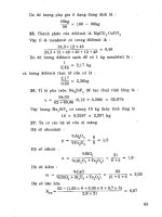
Fig. 6.50 This is the first generation DDEC electronic control system for the GM unit
injectors. It differs from the second generation system in that the command pulse and
feedback are directed to and from the injectors through an EDU instead of directly.
The EDU (electronic distributor unit) functions as a high current switching unit for
energising the solenoids
remains open. The layout of the system is illustrated diagrammatically in
Figs 6.51 and 6.52. Fuel is drawn from the tank, through a filter to a gear
type pump and thence into the governor, whence it passes through a throttle
valve and a shut-down valve, to the pipeline that delivers it to the injectors.
Of these components, all between the pipelines from the tank and to the
injectors are actually grouped in a single unit, Fig. 6.53, into which both the
spin-on filter may be screwed and the drive taken, either directly or in
tandem with another auxiliary such as the compressor, from the engine to the
gear type pump. Delivery pressure from the fuel pump will be subsequently
boosted to the injection pressure by the cam and rocker mechanism, so it
does not have to be more than 1750 kN/m
2
as compared with well over
70 000 kN/m
2
for injectors in which the valves have to be opened by hydraulic
pressure supplied from an external pump.
The governor, which is of the rotating twin bob-weight type, regulates
only maximum and idling speeds. It does this by moving a spool valve
axially between stops to limit the rate of supply of fuel at its two extreme
positions. From zero load up to maximum speed at any load, the driver
effects control through the accelerator pedal, which actuates the throttle in
the fuel delivery line. When maximum speed is attained at full load (maximum
power output), the throttle valve lever is in the maximum fuel position, so the
pressure, and therefore quantity of fuel delivered, is at its maximum. If the
load is then increased, the engine speed and, with it, the fuel pressure from
the gear type pump will fall. This fall in speed causes the mechanical governor
to relax its axial pressure on its return spring, called the torque spring, thus
235 Diesel injection equipment and systems
6
7
4
3
5
1
2
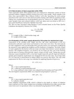
for actuating the injector
1 Fuel from tank
2 Gear type pump
3 Governor/pressure regulator
4 Hydraulic throttle
5 Shut-down valve
6 Injector
7 Cam, roller follower and pushrod
Fig. 6.51 Diagram of the Cummins PT injection system hydraulics
allowing the spool valve to move to the left, in Fig. 6.51, to reduce the
quantity of fuel recirculating back to the induction side of the pump.
Consequently, more fuel is delivered through the driver-controlled throttle in
the delivery line to the injectors. Another, but natural, consequence of a fall
in engine speed is that the duration of opening of the injector orifice increases,
so more fuel can enter the injector cup. Both effects increase the engine
torque as the speed and power fall off.
The shut-down valve simply cuts off the fuel supply. It is actuated either
electrically, pneumatically or manually.
For turbocharged engines, an air–fuel control (AFC) valve is introduced
into the main control unit, Fig. 6.53. This is a spool valve actuated by a
236 The Motor Vehicle
Fig. 6.52 Diagram showing layout of Cummins PT system
diaphragm exposed to the boost pressure, and it is interposed between the
throttle and shut-down valves. If the accelerator pedal is suddenly depressed,
and throttle valve in the fuel supply system thus opened, the passage on to
the injectors is restricted by the AFC valve which, progressively opening,
limits the rate of increase of flow to match that of the boost pressure. This
avoids the emission of black smoke while the turbocharger is accelerating to
catch up to supply enough air for combustion for coping with the extra load.
Other components in the main control unit include a magnetic screen
between the gear type pump and the governor, to take out any particles of
metal that might damage or impair the operation of the unit injectors; a
pulsation damper to smooth out the delivery from the pump; and a spiral
gear for driving a tachometer. A screw on the end remote from the bob-
weights on the governor shaft limits the axial movement of the governor
sleeve away from it, for setting the idling speed.
The injectors are illustrated in Fig. 6.54. At the beginning of the upstroke,
in preparation for the next injection, fuel from the low pressure manifold
enters at A, passes through the inlet orifice B, and on down through a series
of drilled holes, turns up to pass through a check valve F, and then down
again to an annular groove in the top end of the injector cup, whence it flows
up yet again through passage D into the waisted portion of the stem of the
injector. From there it flows out and up through passage E on its way back
to the tank. This fuel flow cools the injector and tends to warm the fuel in the
237
1 Shut-down valve
2 Fuel to injectors
3 Pulsation damper
4 Tachometer shaft
5 Filter screen
6 Fuel inlet
7 Gear pump
8 Air-fuel control barrel
9 Main shaft
10 Drive coupling
11 Throttle shaft
12 Idle speed adjusting screw
13 By-pass ‘button’
14 Governor plunger
15 Torque spring
16 Idle spring pack
17 Governor weights
Fig. 6.53 The combined control, governor and pump unit of the Cummins PT system
Diesel injection equipment and systems
238 The Motor Vehicle
E
A
B
F
D
E
F
D
C
D
C
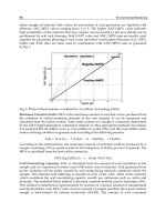
Start upstroke Upstroke complete Downstroke
(fuel circulates) (fuel enters injector cup) (fuel injection)
Fuel at low pressure enters As injector plunger moves As plunger moves down
injector at (A) and flows upward, metering orifice and closes metering orifice,
through inlet orifice (B), (C) is uncovered and fuel fuel entry into cup is cut
internal drillings, around enters injector cup. Amount off. As plunger continues
annular groove in injector is determined by fuel pressure. down, it forces fuel out of
cup and up passage (D) to Passage (D) is blocked, cup through tiny holes at
return to fuel tank. Amount momentarily stopping high pressure as fine spray.
of fuel flowing through circulation of fuel and This assures complete
injector is determined by isolating metering orifice combustion of fuel in
fuel pressure before inlet from pressure pulsations. cylinder. When fuel passage
orifice (B). Fuel pressure (D) is uncovered by plunger
in turn is determined by undercut, fuel again begins
engine speed, governor to flow through return
and throttle. passage (E) to fuel tank.
Fig. 6.54 Sequence of operations of Cummins unit injector: (left) start;
(centre) upstroke; (right) downstroke
tank, thus helping to prevent wax formation in very cold weather. The quantity
of fuel flowing is a function of its pressure which, in turn, is primarily a
function of engine speed but modified by the restrictions imposed by the
governor, throttle valve and, in the case of a turbocharged engine, the AFC
valve.
As the upstroke is completed, the metering orifice C is uncovered, and the
circulation back to the tank is interrupted by the closure of the passage D.
Pulsations in the supply from the fuel pump are absorbed by the pulsation
damper in the control unit so, with the closure of passage D, the flow through
orifice C is steady. Therefore the quantity of fuel passing through this orifice
into the injector cup is a function of its pressure. Any back-flow will close
the check valve F.
On the next injection stroke the downwardly moving plunger first shuts
off the fuel supply coming through the metering orifice C and thus traps the
metered quantity of fuel in the injector cup. Since no more fuel can subsequently
pass in from the metering orifice, there is no possibility of dribbling through
the injector holes after the injection stroke has been completed.
Continuing down, the plunger pressurises the fuel in the cup and forces it
Diesel injection equipment and systems 239
out through tiny holes in the nozzle, spraying it into the combustion chamber.
Toward the end of the stroke, the passage D is once more uncovered, and the
cooling flow of fuel back to the tank resumed. On completion of injection,
the tapered end of the plunger momentarily remains on its seat, in the bottom
of the cup, until the next metering and injection sequence begins.
6.45 The GM unit injection system
In basic concept, the GM unit injection, Fig. 6.55, bears some similarity to
the Cummins PT system just described, but it differs in many respects. First,
there is no separate unit housing all the control functions: instead, each
injector, Fig. 6.56, houses what is virtually a single element of a jerk pump,
such as that illustrated in Fig. 6.27, and injection is controlled by a multi-
segment toothed rack that extends the full length of the head from the foremost
to the rearmost injectors.
From the tank, the fuel is lifted by a transfer pump, through first a strainer
and then a fine filter, up to the gallery and on into branch pipes connecting
it to the unit injectors. As the fuel enters each injector, at A, Fig. 6.56, it
passes through an additional, small, filter from which ducts take it down
through B into a sleeve in the casting around the injector barrel and plunger.
Thence it flows through the radial port F in the barrel, into the chamber
Fig. 6.55 Diagram showing layout of the General Motors unit injection system
240 The Motor Vehicle
Fig. 6.56 GM unit injector
below the end of the plunger. As the plunger descends, the fuel beneath it is
forced up the axial hole in it and out through a radial hole into the spill
groove. From the spill groove, it flows through the radial port E, on the left
of the barrel, out into the sleeve in the housing. The return passage from the
housing, delivering to the outlet H, is behind that for the inlet. It is of smaller
diameter than the inlet, so that the fuel in the housing remains always under
pressure. The function of the surplus fuel flow is to cool the unit during its
passage through the barrel.
As the plunger is lifted by the return spring at its upper end, it shuts off
Diesel injection equipment and systems 241
the spill port on the left in Fig. 6.56, and then draws fuel through the radial
hole on the right, in the barrel, into the chamber beneath it. Incidentally,
higher up on the right, there is another hole C sloping upwards, to allow fuel
to run into an annular groove in the bore of the barrel, for its lubrication.
When the cam actuates the rocker mechanism, it pushes the plunger down
again, so that its lower end D first shuts off the inlet hole, after which the
upper edge of its spill groove shuts off the spill port E. The closure of the
latter traps a metered quantity of fuel beneath the plunger which, continuing
down, forces this fuel, at increasing pressure, through hole G in the wall of
the cylindrical housing for the needle return spring, whence it passes into the
nozzle. On the pressure of this fuel reaching a predetermined value, it lifts
the piston on which the needle return spring seats and, with it, the needle
from its conical seat, whereupon the fuel sprays out through the holes in the
nozzle into the combustion chamber.
As the plunger returns, the spiral upper edge of the spill groove in the
plunger uncovers the spill port in the barrel, suddenly releasing any pressure
in the fuel remaining in the nozzle so that, subsequently, there can be no
dribble through its spray holes. The surplus fuel flows back through the axial
and radial holes in the plunger into the spill groove, whence it passes out
through the radial hole, on the left in the illustration, back into the main
housing. On completion of the injection cycle, the plunger comes back up to
its original position, with both the inlet and spill ports open, for resumption
of the cooling flow.
The upper edge of the spill groove around the plunger is of spiral form, so
that the spill timing, and thus the metering of the quantity of fuel injected,
can be regulated by rotation of the plunger, This is done by means of the
previously mentioned rack. To stop the engine, the rack is moved to the
right-hand extreme of its travel, rotating the plunger clockwise to the position
where, as can be seen in the illustration, the spill port is at no point shut off
by any vertical displacement of the plunger between the limits of its operation.
6.46 Common rail injection systems
With the current demand for high injection pressures for satisfying the
regulations on exhaust emissions, interest in the common rail system of
injection has intensified. The basic principle stemmed from a Vickers Patent
of 1913, and a practical system first went into production in the USA by the
Atlas Imperial Diesel Engine Company. However, for meeting the requirements
prior to the introduction of legal limits on emissions and noise, the in-line
and, later, the distributor type pumps were more economical to produce and
posed fewer design problems.
In the late 1980s and early 1990s, Fiat and its subsidiaries in Italy developed
a workable system. However, because specialist suppliers could supply a
wide range of manufacturers, and therefore in much larger quantities and at
a lower cost, Fiat decided to drop their own version. The first major producer
in the field for light high speed diesel engines therefore was Bosch. In this
system the common rail serves as the hydraulic accumulator, the compressibility
of the fuel in it catering for injection without significant interference by
pulsation.
Several other common rail schemes have been proposed. For example,
the pressure in the rail can be multiplied by a conventional plunger type unit
242 The Motor Vehicle
injection pump the spill valve of which is controlled electronically by the
ECU. With such a system it is still possible to boost the injection pressure up
to perhaps 2000 bar or more, but it is less compact than the Bosch system
described in the next section. For large engines, a conventional hydraulic
accumulator can be included to supplement the capacity of the common rail.
6.47 The Bosch system
As can be seen from Fig. 6.57, the fuel is lifted by the low pressure pump in
the tank, through a filter to the roller cell type high pressure pump, which
transfers it to the forged steel common rail. This rail, extends approximately
the full length of the cylinder head. Generally about 10 mm diameter and
from 280 to 600 mm long, it serves as a pressure accumulator. For minimum
pressure fluctuation, the rail needs to be as long a practicable but, if too long,
engine starting may be slow. In a well-designed installation, the pressure in
the rail remains virtually constant throughout the injection process, and injection
pressures ranging from 1350 to 1600 bar can be obtained.
From the common rail, a separate pipe takes the fuel to the injector for
each cylinder. The injectors are solenoid controlled, the injection pressure
being nominally that in the common rail. A number of advantages arise out
of this separation of the injection and pressurising functions. First, the injector
in the cylinder head is much more compact than one combining a pump and
injection valve, so there is more room around it for the inlet and exhaust
valves and cooling passages. Second, the injection pressure can be more
easily regulated. Third, two-stage injection is readily effected, simply by
causing the ECU to send signals to the high speed solenoid to open and close
the injection valve twice in rapid succession. In addition to the simplicity
Fuel tank
Pre-supply pump
Pressure control valve
Rail pressure sensor
Common rail
Four injectors
Air mass sensor
Filters
ECU
A
B
C
D
E F
Sensors
Pressure
control
valve
High
pressure
pump
Fig. 6.57 Principal components of the Bosch common rail injection system. The
sensors A to F are as follows: A Crankshaft position; B Camshaft position;
C Accelerator pedal; D Boost pressure; E Air temperature; F Coolant temperature
Diesel injection equipment and systems 243
and compactness of this system, it has the advantage that, if required, injection
into each cylinder can be varied individually by the ECU to compensate for
slight variations in compression ratio due, for example, to wear. Finally,
there are several ways in which the injection characteristic curve can be
shaped, see the penultimate paragraph of Section 6.49.
6.48 Components of the Bosch system
The ECU is served by sensors as follows: temperature and mass flow of the
air passing through the intake filter; pressure of the fuel in the rail; engine
speed and crank angle, which can be sensed from teeth on the rim of the
flywheel; a sensor in the throttle pedal unit transmits signals indicting throttle
position and rate of change of position; and another senses the temperature
of the coolant in the engine.
Illustrated in Fig. 6.58 is the fuel lift pump, which Bosch term the pre-
supply pump. It is of the roller cell type, although gear type pumps can be
employed. For cars, the pressure of fuel delivered from the lift pump is
boosted to that required for injection by the radial plunger type high pressure
(a)
(b)
Fig. 6.58 (a) A characteristic of the roller cell type pre-supply, or fuel lift, pump is an
output with a lower level of pulsation than the principal alternatives. It is generally
installed in the fuel tank. (b) Diagrammatic representation of the cross-section of the
roller cell assembly, illustrating the progress of the fuel from inlet to outlet
244 The Motor Vehicle
pump shown in Fig. 6.59 but, for commercial vehicles, an in-line pump is
employed. The pump is driven at half engine speed, either directly from the
camshaft or through a coupling, chain or toothed belt.
From Fig. 6.57, it can be seen that fuel enters through a connection beneath
the pump, whence it is distributed by ducts to each of the three cylinder
heads. A solenoid-actuated push rod, Fig. 6.60, is situated above each inlet
valve to open it to stop the engine. When actuated, these rods hold each inlet
valve in the open position, thus preventing the pump plungers from boosting
the pressure. In the event of an impact, this cut-off procedure is initiated
automatically.
In normal operation, as the plunger retracts, fuel lift pressure opens the valve.
When the plunger begins its return stroke, the inlet valve closes and the increasing
pressure forces the fuel out through the adjacent delivery valve. It then passes
vertically downwards through a calibrated orifice to a snubber valve, Fig. 6.61,
whence it is delivered through a pipe to the common rail. The snubber valve is in a
horizontal branch off the vertical duct from the calibrated orifice. Its function is primarily
to damp out pressure pulsations that might arise in the rail at idling or at low speed
when the engine is operating under heavy load.
At the lower end of the vertical duct is the pressure regulator, Fig. 6.62.
This comprises an electromagnet with a mushroom shape armature the stem
of which actuates a ball valve. If the delivery pressure is too high, it lifts this
ball valve against the force exerted on it by a coil spring bearing on the
opposite end of the armature, and thus allows fuel in excess of requirements
to return to the tank. To meet the changes in demand for fuel, as the engine
speed and torque vary, the force exerted by the spring is supplemented by the
force exerted by the electromagnet. This force is regulated by signals received
from the ECU.
6.49 Injectors
Injection is controlled by an electromagnetically actuated valve housed within
Fig. 6.59 The high pressure pump is actuated by an eccentric with a ring type
follower which does not rotate. A tappet beneath each plunger seats on each of three
flats spaced 120° around the periphery of the ring. Calibrated restrictors, the function
of which is to damp out pulsations in the flow, can be selected to suit the engine to
which the pump is to be fitted
245 Diesel injection equipment and systems
Armature
Electro-magnet
Push rod
Delivery
valve
Pump
Plunger
Inlet valve
Fig. 6.60 To shut the engine down, a solenoid on each cylinder head is energised to
actuate push rods which hold the inlet valves open so that pressure cannot be
generated to force the fuel through the delivery valves
Fig. 6.61 A Bosch snubber valve for the common rail injection system
246 The Motor Vehicle
Fig. 6.62 The pressure regulator valve
the upper end of the injector body, Fig. 6.63. By virtue of the facts that the
injector does not perform the pressurisation function, and that this valve is
coaxial with the injector body, the whole pencil-like injector assembly
occupies very little space on the cylinder head.
Fuel delivered at injection pressure from the rail enters the body of the
injector through a thimble type filter in a connection immediately below
this valve. It then flows two ways: radially inwards, through what Bosch
term the
input throttle,
to the
valve control chamber,
and also down the
injector body to the tip. This equalises the pressures acting on the lower
end of the injector needle and the upper end of the push rod, which projects
into the valve control chamber. Therefore, the needle cannot lift because it
is held firmly on its seat by its return spring. A major advantage is that,
because the pressures are equal at both ends, the injector needle can be
lifted extremely rapidly by a relatively small force. Consequently, injection
is quiet.
When the solenoid is energised, it lifts its valve off a seat at the upper
end of the valve control chamber, thus allowing the fuel in this chamber to
return to the tank. Consequently, the rail pressure, acting on the lower end
of both the needle and push rod, lifts the needle and injection begins. While
the valve is open, some fuel flows through the calibrated restrictor, or input
247 Diesel injection equipment and systems
Fig. 6.63 When the injector is inoperative, the valve spring and the hydraulic pressure
in the control chamber hold the ball valve down. When the solenoid is energised, it
overcomes the valve spring force. Consequently, the pressure in the control chamber
drops, while that in the nozzle chamber, acting on the area of the lower end of the
needle valve, including that of the chamfer, lifts the needle to start injection
throttle, the control chamber and return pipe, to the tank. This recirculation
helps to cool the injector. Additionally, the shape of the injection curve can
be effected by both calibration of this restrictor orifice and regulation, through
the medium of the ECU, of the current through the solenoid.
When the current to the solenoid is cut, the valve is closed by its return
spring and the pressure in the tiny volume of the valve control chamber rises
248 The Motor Vehicle
rapidly to that of the fuel in the rail. Consequently, the pressures on both
ends of the push rod and needle valve again equalise, and the needle valve is
closed by its return spring. By virtue of the light weight of the short needle
valve, its closure is rapid and valve bounce is prevented by the rapidly rising
pressure in the valve control chamber.
6.50 Diesel fuel filtration in general
Four types of contamination must be removed from diesel fuel. These are:
organic sludge, inorganic abrasive debris, water and wax crystals. The
clearances between pump plungers and barrels is of the order of 1 to 2
µ
m.
To avoid wear, scoring, or seizure of these parts, filters capable of trapping
particles of 5
µ
m are a minimum requirement. Distributor type pumps are
even more sensitive to debris in the fuel than are the in-line type.
Shear between the abrasive particles and the edges of the delivery and
spill ports and the edges of the plungers as they sweep over them can also
cause wear. The trapping of debris on the seats of valves can cause injector
nozzle dribbling and, consequently, carbon build-up, although sticking valves
can have a similar effect. In the distributor type pumps, debris can cause
rapid abrasion and wear of the fine ducts through which the fuel passes at
very high pressures and velocities.
Water can enter the tank from the bulk storage supplies on the service
station forecourt or at the oil company’s fuel depot. Moreover, when the
vehicle is refuelled in the rain, some drops can fall into the filler tube. Also,
water vapour in the air drawn into the tank as the fuel is used, may condense
overnight and sink to the bottom of the fuel remaining in it. Water is soluble
in diesel fuel (parabolically) from 0.1 ml/gal at 0°C to 1.0 ml/gal at 80°C.
Sulphur and other contaminants, including bacteria, in combination with the
water in the fuel, may form acids that will corrode the tank and diesel
injection equipment. Moreover, because of the inferior lubricating properties
of water, it can cause scuffing and rapid wear of pumping elements.
Wax, as explained in Sections 17.17 and 17.26–29, can cause the engine
to fail to start. Usually, however, it runs for several minutes and then, when
sufficient wax has collected in the filter to block it, it stalls. The engine will
not start again until the temperature has risen high enough to dissolve the
wax. Fuel additives can help to overcome the problem, and so also can electric
heater elements.
These elements, generally between about 100 and 300 W, may be installed
in either the agglomerator or the main filter. Thermostatic control is desirable
to prevent overheating of the fuel. Alternatively a negative coefficient heating
element (one whose resistance increases with temperature) may be employed.
Generally, although not always, the heater is sited above the filter element.
An argument for placing it below is that the heated fuel will tend to rise but,
when the fuel is flowing downwards, this is of doubtful validity. Heater
elements may be plates or blocks installed in the head, or in tubular form
around the inlet pipe. Stanadyne produce filters with tubular elements of
diameters small enough to be inserted axially into the inlet connection or
suspended in the top of the tube down which the fuel flows into their
FuelManager filter.
On the other hand, with high quality fuel, all that may be necessary,
except in the most severe climates, is to mount the filter close the engine and
Diesel injection equipment and systems 249
to fit radiator blinds to keep engine temperature high. A point liable to be
overlooked is that it is inadvisable to fit a strainer on the fuel pickup in the
tank, because this is where wax crystals are most likely to collect and congeal.
6.51 Filtration and system layouts
For equipment, such as tractors and other off-road vehicles, operated in
extremely dusty conditions, a filter may have to be fitted over the outer end
of the fuel tank vent pipe to prevent dust particles larger than about 7
µ
m
from entering it. The size of the vent needs to be severely restricted because,
with the fuel swilling around in the tank, air is continuously flowing in and
out. A road-going commercial vehicle, on the other hand, generally does not
need a vent filter, but usually has a combined water separator and agglomerator,
or primary filter, for removal of the heavier particles and main, or secondary,
fuel filter, while cars may have only one fuel filter.
The comprehensive fuel supply system might comprise a water separator
or agglomerator in the line from the tank to the fuel lift or feed pump. Fuel
under pressure is then delivered through a fine filter or combined filter and
separator to the injection pump, in the top of which a pressure relief valve
discharges, in the case of a rotary type, back to the inlet side of the transfer
pump or, for the in-line type, into a return line back to the tank. An electric
heater might be incorporated in this return line, to prevent accumulation of
wax in the tank.
The useful life of a filter is a function of the area and porosity of the
filtration element. Therefore paper element filters offer the best compromise
between length of life and particle retention. The paper may be embossed or
crêped to separate the surfaces and thus allow the fuel to spread over them.
It is generally resin impregnated, for stiffness and strength, and to increase
its durability. All such elements are cylindrical, the fuel generally passing
radially inwards through the rings into a central tube which passes it to the
outlet. They are produced in any of three forms: a stack or wound spiral of
V-section folded rings, Fig. 6.64; a simple star-shaped cylinder; or a simple
stack of paper rings, forming an edge type filter, which is rarely used now.
Star-shaped filter elements, associated originally with the early felt types,
are not so effective as the stacked folded V-section paper ring type, so they
tend to be used in agglomerators rather than in main filters.
In agglomerators, the water or heavy particles are stopped by either a
filter or a fine strainer, whence they drop into a sedimenter base below. This
base may be transparent and have a drain plug at its lowest point. If it is not
transparent, it generally has an electrical water sensor in its base, to indicate
when the water needs to be drained off.
An alternative, not used much now because an agglomerator is more
effective, is the simple water separator, or sedimenter, Fig. 6.65. In such
units, the fuel enters at the top, where its velocity of flow is reduced because
of the increased area of its flow path. It passes over a conical baffle and
flows around its periphery and down the walls of the sedimentation and
separator bowl. The water falls to the bottom of the bowl and the fuel rises
up in the centre to leave by a port in the top of the conical baffle, whence it
turns through a right angle to leave the unit diametrically opposite the inlet
port. The bowl is transparent so that the water that has collected in it can be
seen, and there is a drain plug in the base for draining it off.
250 The Motor Vehicle
Fuel flow
Fuel flow
folded
paper
V-section
Fig. 6.64 A diagrammatic representation of the fow through a folded, or bonded,
V-section paper element for a fuel filter
A bracket-mounted CAV combined filter and agglomerator is illustrated
in Fig. 6.66. This unit can be mounted on either the engine or surrounding
structure, or it can be adapted for mounting on the injection pump. It has a
cast head and all the components of the filter and agglomerator are held
together by a single bolt passing through from top to bottom, so that it can
Out
In
Out
Sedimenter head
Conical
diffuser
Sedimenter
chamber
Filter paper
element
Sedimenter
chamber
Drain plug
Drain plug
Filter
agglomerator
head
in
bowl
Transparent
Fig. 6.65 The simple water separator, or
Fig. 6.66 In this CAV unit water droplets
sedimenter, generally has a glass bowl,
agglomerate on the clean side of a filter
so that accumulation of water or
element and, together with heavy
sediment can be easily observed
particles of sediment, drop down into the
sedimenter below
251 Diesel injection equipment and systems
be easily dismantled for changing the filter element and cleaning the unit.
Again, the sedimentation chamber is transparent and a drain plug is fitted so
that water can be drained off.
The unit illustrated is an early version which had a filtration element
comprising a double spiral of crêped resin-impregnated folded concertina
fashion paper, wound around a tubular core and contained within a metal
cartridge, for ease of replacement. In the latest version, the filtration element
is of the type illustrated in Fig. 6.64. Two strips of crêpe paper are wound on
to the core. Prior to winding, one of the strips is coated with a bonding agent
along one edge of one side and the other edge of the other side. These edges
bond together during the winding operation, to form the multi-V section
illustrated.
Fuel enters through a radial port in the head and passes down through
perforations in the top plate, through the filtration element and out through
holes around the periphery of the bottom plate. It then descends into the
sedimentation chamber, where any water or other contamination not trapped
in the filtration element drops to the bottom. The filtered fuel passes up through
the central tube, whence it is directed through the outlet, which is diametrically
opposite the inlet.
A manually actuated priming pump can be fitted either directly to the
filter head or screwed into the fuel inlet connection. It is used to purge the
system of air after the filtration element has been changed. This is particularly
necessary where a suction type fuel lift pump is employed. To cater for very
cold conditions, Lucas offer a 150 W or 300 W electric heater, which can be
interposed between the head and body of a wide range of their filter and
water trap products.
Chapter 7
Distributor type pumps
Distributor type pumps were introduced to provide lighter, more compact
injection pumps than the traditional in-line type. The first was a 1947 design
by Vernon de Roosa of the Hartford, USA, division of the Machine Screw
Company, later to become Stanadyne, Section 7.31. All cylinders of the
engine were served by two diametrically opposed plungers in a single distributor
rotor. Another significant new feature of this pump was inlet, instead of spill,
metering. This made it almost self-governing, so only a simple low cost
governor needed to be added.
Pumps currently in production fall into two categories: the radial and the
axial plunger rotary distributor type pump. As already indicated, the Vernon
de Roosa pump was of the rotary distributor type, sometimes called simply
the rotary type, exemplified by the Lucas and Bosch VP44 versions as well
as the Stanadyne series. Pumps having four, and even three, plungers have
been developed, although the latter, by Stanadyne, was never produced
commercially. The Bosch VE series differ slightly in that, instead of radial
plungers, they have a single plunger housed axially in the distributor rotor.
Rotary injection pumps generally incorporate a transfer pump, sometimes
termed a supply pump, not only to keep the injection pump full of fuel but
also to power some of the control functions. For these functions, transfer
pressures approaching at least about 8 bar are required, so the transfer pumps
are usually of the vane type.
7.1 Lucas DP series distributor type pumps
Three types of distributor pump, derived from the original Vernon de Roosa
unit, have been introduced by Lucas Diesel Systems. The DPA was the first
and was originally intended for all applications. It was followed by the DPC
designed for indirect injection engines for cars and car-derived vans. Then
came the DPS for two different types of application: high speed direct injection
diesel engines of about 0.5 litres per cylinder, and naturally aspirated or
turbocharged direct injection engines, of about 1 litre per cylinder, for
agricultural tractors, industrial and light duty trucks.
7.2 Lucas DPA type pump
The high cost of the in-line pump relative to that of a small engine was the
252
253 Distributor type pumps
incentive for the development by Lucas of the DPA rotary distributor type
injection pump. A diagram showing the overall arrangement of a fuel system
for such a pump is shown in Fig. 7.1, and the pump is illustrated in Fig. 7.2.
Immediately inside one end of the housing, and mounted on the drive
shaft, is the governor. To the right of the governor, as viewed in Fig. 7.2, is
an articulated splined muff coupling connecting it to the end of the drive
Permanent bleed return line
Return from cambox
Filter
Regulating valve
Cam
rollers
Cam
ring
Plungers
Metering
valve
Throttle
link
Linkage
hook
Governor
arm
Thrust sleeve
Drive shaft
Governor weights
Fuel tank
Pivot
Idling spring
Governor spring
Injectors
pump
Back-leak
Sedimenter
Engine-driven
feed pump
with primer
Shut-off bar
Transfer
Sleeve
output
ports
Distributor
port
Inlet
ports
Fig. 7.1 Fuel system with DPA pump and mechanical governor
Control lever
Stop lever
Cam ring
Metering valve
High press outlet
Fuel inlet
Hyd. head
Drive shaft
Transfer pump
Plunger
Regulator valve
Mechanical governor
Advance device
Rotor
Fig. 7.2 DPA Pump
254 The Motor Vehicle
shaft to the rotor. This rotor, which houses the diametrically opposed plungers,
has an integral extension serving as the fuel injection distributor. Surrounding
the plunger rotor is a cam ring. Interposed between it and the plungers are
cam followers in the form of shoes sliding in radial slots in the rotor, Fig.
7.3. Mounted on an extension of the right-hand end of the rotor is the vane
type transfer pump.
This whole rotor assembly is in a steel housing termed the hydraulic
head, in which is a ported cylinder carrying the distributor portion of the
rotor. A controlled degree of leakage passes from the hydraulic head into the
cam box, in which the maximum pressure is limited by the pressurising
valve which, in Figs 7.2 and 7.7, projects vertically upwards from the rear,
or driven, end of the pump. The hydraulic head is spigoted into the rear end
of the cam box, the top of which is closed by an inverted bath tub-shaped
casting that houses the governor control springs and linkage. Controls actuated
by the driver are linked to levers on the upper ends of vertical spindles
rotating in bearings in the top of this cover. Levers on the lower ends of these
spindles are connected to the governor controls.
Maximum travel, and therefore maximum delivery is adjusted on the
production line. Lugs extend outwards from the ends of the shoes, Fig. 7.3,
to register in cam-shaped slots in two side plates, which are clamped to the
rotor by screws passing through slotted holes in them. The screws are loosened
and the plates rotated relative to the rotor, to cause the shoes to ride up, or
down, in the cam-shaped slots to the appropriate maximum delivery setting.
The screws are then tightened again. Actual delivery is determined by the
driver, and modified by the governor. To perform its function, the governor
varies the rotational setting of a restrictor. This restrictor, termed the metering
valve, limits the quantity of fuel that can flow to the plungers in the time
available, and therefore their outward strokes. The delivery pressure of the
pump increases with speed up to a maximum determined by the setting of a
pressure limiting valve in the pump end plate.
As the rotor turns, it opens each inlet port in the distributor sleeve one
after the other. Fuel from the transfer pump is delivered into a radial hole in
the rotor, and then through an axial hole towards the end of the rotor, where
it enters the space between the plungers. Transfer pump pressure forces the
plungers outwards while, at the same time, filling the space between them.
To avoid dribbling at the nozzles at the end of injection, the cut-off must be
sharp, so the cam profiles include what are termed retraction profiles, Fig.
7.17. These allow the plungers to retract a short distance outwards, before
B
A
A Cam-shaped slot
C
B Lug on roller shoe
C Roller shoe
D Roller
D
E Plunger
E
F Adjusting plate
G Locking screw hole
G
F
in shoe carrier
Fig. 7.3 The method used to adjust the maximum travel of the plungers
255Distributor type pumps
the fuel begins to enter to drive them further outwards on their normal
induction stroke. Therefore, at the end of injection, the delivery pressure is
instantly reduced although, between the injection phases, some residual pressure
is maintained in the line.
When the plungers are driven inwards by a pair of cams, the fuel between
them is forced out at very high pressure through first the axial hole and then
a single radial delivery hole. As the rotor turns, the delivery hole is aligned
at regular timed intervals with ports in the distributor sleeve. The shots of
fuel pass along ducts in the hydraulic head, through the delivery valves, into
the pipes serving each of the cylinders in turn. So the porting and flow
sequence for delivery is exactly the inverse of that for the incoming fuel to
the plungers. Accuracy of spacing of the delivery ports and the cams is
essential for obtaining precise timing intervals between injections.
To keep the engine speed constant regardless of variations in load, the rate
of delivery of fuel to the plungers is regulated by the rotary metering valve.
Since the quantity of fuel delivered by the transfer pump increases with
speed, it is necessary for the rollers to contact the plungers at points dependent
on movements of both the governor linkage and the accelerator. Consequently,
the return spring for the governor arm is connected by an arm and linkage to
the accelerator pedal, Fig. 7.1, and the rotary metering valve is actuated by
a link between it and the governor arm.
As load is reduced, so also are the outward movements of the plungers.
Consequently, they make their initial contacts further up the profiles of the
cams and therefore later. Therefore, if the injection timing is set for maximum
load and speed, it must be progressively retarded as the speed falls. The
mechanism for doing this is illustrated in Fig. 7.4.
Screwed radially into the periphery of the cam ring is a short ball-ended
lever projecting downwards into a hole in the plunger of a hydraulic servo,
which is aligned tangentially relative to the cam ring. Axial displacement of
the plunger therefore rotates the cam ring. A coil spring pushes the plunger
to one end of its cylinder, to retard injection, while fuel transfer pressure
advances it by pushing the plunger back against the load exerted by the
spring. A non-return valve in the delivery from the transfer pump to the
Retard
Advance
Fig. 7.4 The injection timing is controlled
automatically by moving the cam ring
256 The Motor Vehicle
plunger prevents the timing from being retarded by the impacts of the roller
followers on the cams.
For starting and low speed operation, when the transfer pressure is low,
the plunger is, of course, in the fully retarded position. However, with some
high speed engines, further retardation could occur owing to the previously
mentioned impact between the plungers and cams. However, this is avoided
by the incorporation of a light load advance device, to be described in the
next section.
7.3 DPA pump governor
In general, the basic principles of the all-speed governing system are identical
to those of governors for in-line pumps. A spring is interposed between the
governor control arm and the linkage to the accelerator pedal. This spring is
compressed increasingly with speed, thus opposing the force exerted by the
governor weights, to a degree such that the engine speed remains constant
regardless of load.
Hydraulic governing, Fig. 7.5, used to be an option. However, owing to
lack of demand, it is no longer produced. It functioned as follows. Transfer
pump pressure lifts the metering valve against the force exerted by the two
springs above. One of these two, that below the rack, is the main governor
spring, while the smaller one above is the idling spring. The valve stem
slides freely within the rack, which meshes with a pinion on which is mounted
a lever linked to the accelerator pedal. The disc seated in the countersink
immediately above the valve serves as a damper. This prevents the lever from
moving too precipitately and thus, if the accelerator pedal is suddenly closed,
stalling the engine.
During idling, only the lighter of the two springs deflects to keep the
engine speed constant, the main spring coming into operation as the driver
calls for more torque. To stop the engine, the driver pulls a shutdown lever
linked to the spindle on the end of which is an eccentric lug. This lug lifts the
valve and thus cuts off the fuel supply.
Mechanical governing takes up more space, is more costly but also more
precise. Displacement of the governor weights actuates the linkage connected
to the lever on the upper end of the rotary metering valve. These weights are
pivoted in a star-shaped housing and they slide a sleeve along the rotor shaft,
lever
Dashpot
Throttle
lever
Shut off
To rotor
Fig. 7.5 Hydraulic governor
Distributor type pumps 257
Fig. 7.6. The opposite end of this sleeve bears against the lower end of a
lever pivoted on a knife edge at a level approximately in line with the top of
the housing for the weights, so that its upper end will actuate the linkage that
rotates the metering valve. Rotation of this valve regulates the flow of fuel
through the axial groove machined in its periphery at its lower end, into
ducts leading to the space between the two opposed plungers.
Two spindles pivoted in the top cover have, at their upper ends, lever
arms, one of which is connected to the throttle pedal and the other to a shut
down lever on the dash. At the lower end of one of these spindles is a lever
connected to the governor spring and, extending downwards from lower end
of the other, is an eccentric peg which registers between the arms of the U-
shaped end of a horizontal push rod. As can be seen from Fig. 7.6, the other
end of this push rod bears against one end of the lever that rotates the
metering valve. When the shutdown lever is actuated, the push rod turns the
metering valve far enough to cut off the fuel supply. It does this against the
resistance offered, at its far end, by a light spring around a rod the other end
of which is free to slide in a hole through the governor lever.
During normal running, the governor spring is under tension. For idling,
however, the governor lever position is determined by equilibrium between
the residual tension in this spring and compression in the shorter compression
spring on the other side of the governor lever.
7.4 Lucas DPS pump
The DPS pump, Fig. 7.7, was introduced to provide both torque and boost
control for four- and six-cylinder engines. It operates on principles virtually
identical to those of the DPA, but it has some additional features. For instance
it can have either two or four opposed plungers, in one or two diametrical
bores respectively, in the rotor. The axes of the plungers are all in a common
plane. The four plunger version is for large engines of the in-line and 90° and
60° V layouts. Alternatives of two- or all-speed governing and belt drive are
available, and excess fuel for starting is automatic. Maximum fuel delivery
is externally adjustable, and shutdown can be effected with an electrical key
switch.
The drive shaft is stiffer than that of the DPA and, for taking the extra
loading imposed by a belt drive, it is carried in two bearings, one each side
Fig. 7.6 Arrangement of the linkage between
the mechanical governor, bottom left, and the
metering valve, bottom right
258 The Motor Vehicle
Fig. 7.7 This version of the Lucas DPS distributor type pump, designed for a heavy
duty belt drive, is for high speed DI engines. Although similar to the DPA, it has
stiffer drive
of the governor assembly. To transmit the drive from the drive shaft to the
rotor, a tongue in the end of the latter registers in a slot in the end of the drive
shaft. The arrangement of the ducting in the rotor, distributor and hydraulic
head for filling the chamber and the delivery and distribution of the fuel to
the injectors is similar to that of the DPA pump.
Spigoted into a counterbore in the end of the hydraulic head is the eccentric
cam-form ring within which the vanes of the transfer pump rotate. If there is
no lift pump, the pressure in the feed line is generally sub-atmospheric, so it
would be possible for air to be drawn in to supply the pumping chambers.
Therefore, there is a duct with a restricting orifice in its inner end to vent air
from the counterbore into the injection pump housing, Fig. 7.8.
A groove, in the same plane as the distributor port, is machined most of
the way around the periphery as shown in Fig. 7.8. It interconnects all the
delivery ducts, except that which is about to deliver to an injector, and its
function is to balance the residual pressures in the others. Housed in the
banjo connection to each of the delivery ports around the pump is a high
pressure delivery valve. When injection terminates, fuel can flow back through
a small hole drilled axially through it, into the equalising groove around the