Understanding Automotive Electronics 5 Part 13 pptx
Bạn đang xem bản rút gọn của tài liệu. Xem và tải ngay bản đầy đủ của tài liệu tại đây (1.2 MB, 30 trang )
DIAGNOSTICS
10
UNDERSTANDING AUTOMOTIVE ELECTRONICS
349
6. With code 76 displayed and the cruise control instrument panel switch
on, depress and release the set/coast button. If the button (switch) is oper-
ating normally, the display advances to 77.
7. With 77 displayed and with the cruise control instrument on, depress and
release the resume/acceleration switch. If the switch is operating normally,
the display advances to 78.
8. With 78 displayed, depress and release the instant/average button on the
MPG panel. If the button is working normally, the code advances to 79.
9. With 79 displayed, depress and release the reset button on the mph panel.
If the reset button is working normally, the code will advance to 80.
10. With 80 displayed, depress and release the rear defogger button on the cli-
mate control head. If the defogger switch is working normally, the code
advances to 70, thereby completing the switch tests.
With code 70 displayed, the engine data can be displayed in sequence by
switching the cruise control instrument panel off. The code should then
advance to 90. To further advance the display, the mechanic must depress the
instant/average button on the MPG panel (to return to the previously displayed
parameter, the mechanic must depress the reset button on the MPG panel). To
exit the engine parameter display mode, the mechanic simultaneously depresses
the Off and Hi buttons on the climate control head. After the last parameter
has been displayed, the code advances to 95.
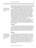
Figure 10.11 shows the parameter values in sequence. Parameter 01 is the
angular deflection of the throttle in degrees from idle position. Parameter 02 is
the manifold absolute pressure in kilopascals (kPa). The range for this
parameter is 14 to 99, with 14 representing about the maximum manifold
vacuum. Parameter 03 is the absolute atmospheric pressure in kPa. Normal
atmospheric pressure is roughly 90–100 kPa at sea level. Parameter 04 is the
coolant temperature. The conversion from this code to an actual temperature is
given in Table 10.2. Parameter 05 is the manifold air temperature, which uses
the same conversion as parameter 04.
Parameter 06 is the duration of the fuel injector pulse in msec. In reading
this number, the mechanic assumes a decimal point between the two digits (i.e.,
16 is read as 1.6 msec). Refer to Chapters 5, 6, and 7 for an explanation of the
injector pulse widths and the influence of these pulse widths on fuel mixture.
Measurements of aver-
age O
2
sensor voltage are
useful for diagnosis of
this sensor.
Parameter 07 is the average value for the O
2
sensor output voltage.
Reference was made earlier in this chapter to the diagnostic use of this parameter.
Recall that the O
2
sensor switches between about 0 and 1 volt as the mixture
oscillates between lean and rich. The displayed value is the time average for this
voltage, which varies with the duty cycle of the mixture. A decimal point should
be assumed at the left of the two digits (i.e., 52 is read as 0.52 volt).
Parameter 08 is the spark advance in degrees before TDC. This value
should agree with that obtained using a timing light or engine analyzer.
Parameter 09 is the number of ignition cycles that have occurred since a trouble
2735 | CH 10 Page 349 Tuesday, March 10, 1998 1:27 PM
10
DIAGNOSTICS
350
UNDERSTANDING AUTOMOTIVE ELECTRONICS
code was set in memory. If 20 such cycles have occurred without a fault, this
counter is set to zero and all trouble codes are cleared.
Parameter 10 is a logical (binary) variable that indicates whether the
engine control system is operating in open or closed loop. A value of 1
corresponds to closed loop, which means that data from the O
2
sensor is fed
back to the controller to be used in setting injector pulse duration. Zero for this
variable indicates open-loop operation, as explained in Chapters 6 and 7
Parameter 11 is the battery voltage minus 10. A decimal point is assumed
between the digits. Thus, 2.3 is read as 12.3 volts.
After completion of parameter data values, the climate control display will
advance to 95. The remaining codes are specific to certain Cadillac models and
are not germane to the present discussion.
Once the mechanic has read all of the fault codes, he or she proceeds with
the diagnosis using the shop manual in the same manner as explained for the
Cadillac example. For each fault code there is a procedure to be followed that
attempts to isolate the specific components that have failed. Obviously, the
Figure 10.11
Engine Data
Display
FPO
2735 | CH 10 Page 350 Tuesday, March 10, 1998 1:27 PM
DIAGNOSTICS
10
UNDERSTANDING AUTOMOTIVE ELECTRONICS
351
process of diagnosing a problem can be lengthy and can involve many steps.
However, without the aid of the on-board diagnostic capability of the electronic
control system, such diagnosis would take much more time and might, in
certain cases, be impossible.
On-board diagnosis has also been mandated by government regulation,
particularly if a vehicle failure could damage emission control systems. The
California Air Resources Board (CARB), which has been at the forefront of
Table 10.2
Temperature
Conversion Table
CODE ˚F
0 –40
8 –12
12 1
16 15
21 32
25 46
30 64
35 81
40 98
45 115
50 133
52 140
54 147
56 153
58 160
60 167
62 174
64 181
66 188
68 195
70 202
72 209
73 212
75 219
2735 | CH 10 Page 351 Tuesday, March 10, 1998 1:27 PM
10
DIAGNOSTICS
352
UNDERSTANDING AUTOMOTIVE ELECTRONICS
automotive emission control regulations, has proposed a new, relatively severe
requirement for on-board diagnosis that is known as OBDII (on-board
diagnosis II). This requirement is intended to ensure that the emission control
system is functioning as intended.
Automotive emission control systems, which have been discussed in
Chapters 5 and 7, consist of fuel and ignition control, the three-way catalytic
converter, EGR, secondary air injection, and evaporative emission. The OBDII
regulations require real-time monitoring of the health of the emission control
system components. For example, the performance of the catalytic converter
must be monitored using a temperature sensor for measuring converter
temperature and a pair of EGO sensors (one before and one after the converter).
Another requirement for OBDII is a misfire detection system. It is known
that under misfiring conditions (failure of the mixture to ignite), exhaust emissions
increase. In severe cases, the catalytic converter itself can be irreversibly damaged.
The only cost-effective means of meeting OBDII requirements involves
electronic instrumentation. For example, one possible means of detecting
misfire is based on measurements of the crankshaft instantaneous speed. That
speed fluctuates about the average RPM in response to each cylinder firing
event. Misfire can be detected in most cases by monitoring the crankshaft speed
fluctuations using some relatively sophisticated electronic signal processing.
Off-board Diagnosis
An alternative to the on-board diagnostics is available in the form of a
service bay diagnostic system. This system uses a computer that has a greater
diagnostic capability than the vehicle-based system because its computer is
typically much larger and has only a single task to perform—that of diagnosing
problems in engine control systems.
Special-purpose digital
computers are coming
into use in service bay
diagnosis systems.
An example of a service bay diagnostic system is General Motors’ CAMS
(Computerized Automotive Maintenance System). Although the system
discussed here is essentially obsolete, it is at leats representative of this level of
diagnosis. The GM-CAMS used an IBM PC/AT computer that had
considerable computational capability for its time. Its memory included 640K
of RAM, 1.2 million bytes on a 5.75 inch diskette drive and 20 million bytes
on a fixed disk drive. This system was capable of detecting, analyzing, and
isolating faults in late-model GM vehicles that are equipped with a digital
engine control system. This system, commonly called the
technicians’ terminal,
has a modem equivalent that operates in essentially the same way as the CAMS.
The technicians’ terminal is mounted on a rugged portable cart (Figure
10.12) suitable for use in the garage. It connects to the vehicle through the
assembly line data link (ALDL). The data required to perform diagnostics are
obtained by the terminal through this link. The terminal has a color CRT
monitor (similar to that of a typical home computer) that displays the data and
procedures. It has a touch-sensitive screen for technician input to the system.
The terminal features a keyboard for data entry, printer for hard copy output,
2735 | CH 10 Page 352 Tuesday, March 10, 1998 1:27 PM
DIAGNOSTICS 10
UNDERSTANDING AUTOMOTIVE ELECTRONICS 353
and modem for a telephone link to a network that collects and routes GM-
CAMS information.
The GM system also features a mainframe computer system at the
General Motors Information Center (GMIC) that contains a master database
that includes the most recent information relating to repair of applicable GM
cars. This information, as well as computer software updates, is relayed
throughout the network. Mechanics can also obtain diagnostic assistance by
calling the GM-CAMS Customer Support Center.
When using the GM-CAMS, the mechanic enters the vehicle
identification number (VIN) via the terminal. The computer responds by
displaying a menu in which several choices are presented. To select a particular
choice the technician touches the portion of the display associated with that
choice. Next, the computer displays an additional menu of further choices; this
continues until the mechanic has located the desired choice.
Figure 10.12
Engine Data
Display
FPO
2735 | CH 10 Page 353 Tuesday, March 10, 1998 1:27 PM
10 DIAGNOSTICS
354 UNDERSTANDING AUTOMOTIVE ELECTRONICS
The service bay diagnos-
tic system can be readily
updated with new ser-
vice bulletins.
Among the many capabilities of the technicians’ terminal is its ability to
store and display the diagnostic charts that appear in the shop manual.
Whenever a fault is located, the appropriate chart(s) are automatically displayed
for the mechanic. This capability greatly increases the efficiency of the
diagnostic process. In addition, the GM-CAMS computer can store all of the
data that is associated with the diagnostic procedures for several vehicles and
then locate and display, virtually instantaneously, each specific procedure as
required. Furthermore, updates and the most recent service bulletins are
brought into the mechanics’ terminal over the phone network so that
mechanics lose no time trying to find the most recent data and procedures for
diagnosing vehicular electronic systems.
In addition to storing and displaying shop manual data and procedures, a
computer-based garage diagnostic system can automate the diagnostic process
itself. In achieving this objective, the technicians’ terminal has the capability to
incorporate what is commonly called an expert system.
EXPERT SYSTEMS
An expert system is a form
of artificial intelligence
that has great potential
for automotive diagno-
sis.
Although it is beyond the scope of the present book to explain expert
systems, it is perhaps worthwhile to introduce some of the major concepts
involved in this rapidly developing technology. An expert system is a computer
program that employs human knowledge to solve problems normally requiring
human expertise. The theory of expert systems is part of the general area of
computer science known as artificial intelligence (AI). The major benefit of
expert system technology is the consistent, uniform, and efficient application of
the decision criteria or problem-solving strategies.
The diagnosis of electronic engine control systems by an expert system
proceeds by following a set of rules that embody steps similar to the diagnostic
charts in the shop manual. The diagnostic system receives data from the
electronic control system (e.g., via the ALDL connector in the GM-CAMS) or
through keyboard entry by the mechanic. The system processes this data
logically under program control in accordance with the set of internally stored
rules. The end result of the computer-aided diagnosis is an assessment of the
problem and recommended repair procedures. The use of an expert system for
diagnosis can significantly improve the efficiency of the diagnostic process and
can thereby reduce maintenance time and costs.
An expert system takes
information from
experts and converts this
to a set of logical rules.
The development of an expert system requires a computer specialist who
is known in AI parlance as a knowledge engineer. The knowledge engineer must
acquire the requisite knowledge and expertise for the expert system by
interviewing the recognized experts in the field. In the case of automotive
electronic engine control systems the experts include the design engineers as
well as the test engineers, mechanics, and technicians involved in the
development of the control system. In addition, expertise is developed by the
mechanics who routinely repair the system in the field. The expertise of this
latter group can be incorporated as evolutionary improvements in the expert
2735 | CH 10 Page 354 Tuesday, March 10, 1998 1:27 PM
DIAGNOSTICS 10
UNDERSTANDING AUTOMOTIVE ELECTRONICS 355
system. The various stages of knowledge acquisition (obtained from the experts)
are outlined in Figure 10.13. It can be seen from this illustration that several
iterations are required to complete the knowledge acquisition. Thus, the
process of interviewing experts is a continuing process.
Not to be overlooked in the development of an expert system is the
personal relationship between the experts and the knowledge engineer. The
experts must be fully willing to cooperate and to explain their expertise to the
knowledge engineer if a successful expert system is to be developed. The
personalities of the knowledge engineer and experts can become a factor in the
development of an expert system.
Figure 10.14 represents the environment in which an expert system
evolves. Of course, a digital computer of sufficient capacity is required for the
Figure 10.13
Stages of
Knowledge
Acquisition
FPO
2735 | CH 10 Page 355 Tuesday, March 10, 1998 1:27 PM
10 DIAGNOSTICS
356 UNDERSTANDING AUTOMOTIVE ELECTRONICS
development work. A summary of expert system development tools that are
applicable for a mainframe computer is presented in Table 10.3.
It is common practice to think of an expert system as having two major
portions. The portion of the expert system in which the logical operations are
performed is known as the inference engine. The various relationships and basic
knowledge are known as the knowledge base.
The general diagnostic field to which an expert system is applicable is one
in which the procedures used by the recognized experts can be expressed in a set
of rules or logical relationships. The automotive diagnosis area is clearly such a
field. The diagnostic charts that outline repair procedures (as outlined earlier in
this chapter) represent good examples of such rules.
Figure 10.14
Environment of an
Expert System
FPO
Table 10.3
Expert System
Developing Tools for
Mainframes
Name Company Machine
Ops5 Carnegie Mellon University VAX
S.1 Teknowledge VAX
Xerox 1198
Loops Xerox 1108
Kee Intelligenetics Xerox 1198
Art Inference Symbolics
2735 | CH 10 Page 356 Tuesday, March 10, 1998 1:27 PM
DIAGNOSTICS 10
UNDERSTANDING AUTOMOTIVE ELECTRONICS 357
To clarify some of the ideas embodied in an expert system, consider the
following example of the diagnosis of an automotive repair problem. This
particular problem involves failure of the car engine to start. It is presumed in
this example that the range of defects is very limited. Although this example is
not very practical, it does illustrate some of the principles involved in an expert
system.
A typical expert system
formulates expertise in
IF-THEN rules.
The fundamental concept underlying this example is the idea of
condition-action pairs that are in the form of IF-THEN rules. These rules
embody knowledge that is presumed to have come from human experts (e.g.,
experienced mechanics or automotive engineers).
The expert system of this example consists of three components:
1. A rule base of IF-THEN rules
2. A database of facts
3. A controlling mechanism
Each rule of the rule base is of the form of “if condition A is true, then
action B should be taken or performed.” The IF portion contains conditions
that must be satisfied if the rule is to be applicable. The THEN portion states
the action to be performed whenever the rule is activated (fired).
The database contains all of the facts and information that are known to
be true about the problem being diagnosed. The rules from the rule base are
compared with the knowledge base to ascertain which are the applicable rules.
When a rule is fired, its actions normally modify the facts within the database.
The controlling mechanism of this expert system determines which
actions are to be taken and when they are to be performed. The operation
follows four basic steps:
1. Compare the rules to the database to determine which rules have the IF
portion satisfied and can be executed. This group is known as the conflict
set in AI parlance. A conflict set is a type of set, as in set theory.
2. If the conflict set contains more than one rule, resolve the conflict by
selecting the highest priority rule. If there are no rules in the conflict set,
stop the procedure.
3. Execute the selected rule by performing the actions specified in the
THEN portion, and then modify the database as required.
4. Return to step 1 and repeat the process until there are no rules in the con-
flict set.
In the present simplified example, it is presumed that the rule base for
diagnosing a problem starting a car is as given in Figure 10.15. Rules R2
through R7 draw conclusions about the suspected problem, and rule R1
identifies problem areas that should be investigated. It is implicitly assumed
that the actions specified in the THEN portion include “add this fact to the
database.” In addition, some of the specified actions have an associated
2735 | CH 10 Page 357 Tuesday, March 10, 1998 1:27 PM
10 DIAGNOSTICS
358 UNDERSTANDING AUTOMOTIVE ELECTRONICS
fractional number. These values represent the confidence of the expert who is
responsible for the rule that the given action is true for the specified condition.
Further suppose that the facts known to be true are as shown in Figure
10.16. The controlling mechanism follows step 1 and discovers that only R1 is
in the conflict set. This rule is executed, deriving these additional facts in
performing steps 2 and 3:
Suspect there is no spark.
Suspect too much fuel is reaching the engine.
At step 4, the system returns to step 1 and learns that the conflict set includes
R1, R4, and R6. Since R1 has been executed, it is dropped from the conflict set.
In this simplified example, assume that the conflict is resolved by selecting the
lowest-numbered rule (i.e., R4 in this case). Rule R4 yields the additional facts
after completing steps 2 and 3 that there is a break in fuel line (0.65). The value
0.65 refers to the confidence level of this conclusion.
Figure 10.15
Simple Automobile
Diagnostic Rule Base
FPO
2735 | CH 10 Page 358 Tuesday, March 10, 1998 1:27 PM
DIAGNOSTICS 10
UNDERSTANDING AUTOMOTIVE ELECTRONICS 359
The procedure is repeated with the resulting conflict set R6. After
executing R6, the system returns to step 1, and finding no applicable rules, it
stops. The final fact set is shown in Figure 10.17. Note that this diagnostic
procedure has found two potential diagnoses: a break in fuel line (confidence
level 0.65), and mixture too rich (confidence level 0.70).
The previous example is intended merely to illustrate the application of
artificial intelligence to automotive diagnosis and repair.
To perform diagnosis on a specific car using an expert system, the
mechanic identifies all of the relevant features to the mechanic’s terminal
including, of course, the engine type. After connecting the data link from the
electronic control system to the terminal, the diagnosis can begin. The terminal
can ask the mechanic to perform specific tasks that are required to complete the
diagnosis, including, for example, starting or stopping the engine.
The mechanic uses the
expert system interac-
tively in diagnosing
problems.
The expert system is an interactive program and, as such, has many
interesting features. For example, when the expert system requests that the
mechanic perform some specific task, the mechanic can ask the expert system
why he or she should do this, or why the system asked the question. The expert
system then explains the motivation for the task, much the way a human expert
would do if he or she were guiding the mechanic. An expert system is
frequently formulated on rules of thumb that have been acquired through years
of experience by human experts. It often benefits the mechanic in his or her
Figure 10.16
Starting Database of
Known Facts
FPO
Figure 10.17
Final Resulting
Database of Known
Facts
FPO
2735 | CH 10 Page 359 Tuesday, March 10, 1998 1:27 PM
10 DIAGNOSTICS
360 UNDERSTANDING AUTOMOTIVE ELECTRONICS
task to have requests for tasks explained in terms of both these rules and the
experience base that has led to the development of the expert system.
The general science of expert systems is so broad that it cannot be covered
in this book. The interested reader can contact any good engineering library for
further material in this exciting area. In addition, the Society of Automotive
Engineers has many publications covering the application of expert systems to
automotive diagnosis.
From time to time, automotive maintenance problems will occur that are
outside the scope of the expertise incorporated in the expert system. In these
cases, an automotive diagnostic system needs to be supplemented by direct
contact of the mechanic with human experts. The GM-CAMS system, for
example, has incorporated this feature into its customer support center.
Vehicle off-board diagnostic systems (whether they are expert systems or
not) continue to be developed and refined as experience is gained with the
various systems, as the diagnostic database expands, and as additional software
is written. The evolution of such diagnostic systems is heading in the direction
of fully automated, rapid, and efficient diagnoses of problems in cars equipped
with modern digital control systems.
OCCUPANT PROTECTION SYSTEMS
Occupant protection during a crash has evolved dramatically since about
the 1970s. Beginning with lap seat belts, and motivated partly by government
regulation and partly by market demand, occupant protection has evolved to
passive restraints and airbags. We will discuss only the latter since airbag
deployment systems can be implemented electronically, whereas other schemes
are largely mechanical.
Conceptually, occupant protection by an airbag is quite straightforward.
The airbag system has a means of detecting when a crash occurs that is
essentially based on deceleration along the longitudinal car axis. A collision that
is serious enough to injure car occupants involves deceleration in the range of
tens of gs (i.e., multiples of 10 of the acceleration of gravity), whereas normal
driving involves acceleration/deceleration on the order of 1 g.
Once a crash has been detected, a flexible bag is rapidly inflated with a gas
that is released from a container by electrically igniting a chemical compound.
Ideally, the airbag inflates in sufficient time to act as a cushion for the driver (or
passenger) as he or she is thrown forward during the crash.
On the other hand, practical implementation of the airbag has proven to
be technically challenging. Considering the timing involved in airbag
deployment it is somewhat surprising that they work as well as they do. At car
speeds that can cause injury to the occupants, the time interval for a crash into
a rigid barrier from the moment the front bumper contacts the barrier until the
final part of the car ceases forward motion is substantially less than a second.
Table 10.4 lists required airbag deployment times for a variety of test crash
conditions.
2735 | CH 10 Page 360 Tuesday, March 10, 1998 1:27 PM
DIAGNOSTICS 10
UNDERSTANDING AUTOMOTIVE ELECTRONICS 361
Table 10.4
Airbag Deployment
Times
Test Library Event Required Deployment Time
(msec)
9 mph frontal barrier ND
9 mph frontal barrier ND
15 mph frontal barrier 50.0
30 mph frontal barrier 24.0
35 mph frontal barrier 18.0
12 mph left angle barrier ND
30 mph right angle barrier 36.0
30 mph left angle barrier 36.0
10 mph center high pole ND
14 mph center high pole ND
18 mph center high pole ND
30 mph center high pole 43.0
25 mph offset low pole 56.0
25 mph car-to-car 50.0
30 mph car-to-car 50.0
30 mph 550 hop road, panic stop ND
30 mph 629 hop road, panic stop ND
30 mph 550 tramp road, panic stop ND
30 mph 629 tramp road, panic stop ND
30 mph square block road, panic stop ND
40 mph washboard road, medium braking ND
25 mph left-side pothole ND
25 mph right-side pothole ND
60 mph chatter bumps, panic stop ND
45 mph massoit bump ND
5 mph curb impact ND
20 mph curb dropoff ND
35 mph belgian blocks ND
Note: ND = nondeployment
2735 | CH 10 Page 361 Tuesday, March 10, 1998 1:27 PM
10 DIAGNOSTICS
362 UNDERSTANDING AUTOMOTIVE ELECTRONICS
A typical airbag will require about 30 msec to inflate, meaning that the
crash must be detected within about 20 msec. With respect to the speed of
modern digital electronics, a 20 msec time interval is not considered to be
short. The complicating factor for crash detection is the many crashlike
accelerations experienced by a typical car that could be interpreted by airbag
electronics as a crash, such as impact with a large pothole or driving over a curb.
The configuration for an airbag system has also evolved from
electromechanical implementation using switches to electronic systems
employing sophisticated signal processing. One of the early configurations
employed a pair of acceleration switches SW1 and SW2 as depicted in Figure
10.18a. Each of these switches is in the form of a mass suspended in a tube with
the tube axis aligned parallel to the longitudinal car axis. Figure 10.18b is a
circuit diagram for the airbag system.
The two switches, which are normally open, must both be closed to
complete the circuit for firing the squib. When this circuit is complete, a
current flows through the squib ignitor that activates the charge. A gas is
produced (essentially explosively) that inflates the airbag.
The switches SW1 and SW2 are placed in two separate locations in the
car. Typically, one is located near the front of the car and one in or near the
front of the passenger compartment (some automakers locate a switch under
the driver’s seat on the floor pan).
Referring to the sketch in Figure 10.18a, the operation of the
acceleration-sensitive switch can be understood. Under normal driving
conditions the spring holds the movable mass against a stop and the switch
contacts remain open. During a crash the force of acceleration (actually
deceleration of the car) acting on the mass is sufficient to overcome the spring
force and move the mass. For sufficiently high car deceleration, the mass moves
forward to close the switch contacts. In a real collision at sufficient speed, both
switch masses will move to close the switch contacts, thereby completing the
circuit and igniting the squib to inflate the airbag.
Figure 10.18b also shows a capacitor connected in parallel with the
battery. This capacitor is typically located in the passenger compartment. It has
sufficient capacity that in the event the car battery is destroyed early in the
crash, it can supply enough current to ignite the squib.
In recent years there has been a trend to implement electronic airbag
systems. In such systems the role of the acceleration-sensitive switch is played
by an analog accelerometer along with electronic signal processing, threshold
detection, and electronic driver circuit to fire the squib. Figure 10.19 depicts a
block diagram of such a system.
The accelerometers a1 and a2 are placed at locations similar to where the
switches SW1 and SW2 described above are located. Each accelerometer
outputs a signal that is proportional to acceleration (deceleration) along its
sensitive axis.
2735 | CH 10 Page 362 Tuesday, March 10, 1998 1:27 PM
DIAGNOSTICS 10
UNDERSTANDING AUTOMOTIVE ELECTRONICS 363
Under normal driving conditions the acceleration at the accelerometer
locations is less than 1 g. However, during a collision at a sufficiently high speed
the signal increases rapidly. Signal processing can be employed to enhance the
collision signature in relation to the normal driving signal. Such signal
processing must be carefully designed to minimize time delay of the output
relative to the collision deceleration signal.
After being processed, the deceleration signal is compared with a
threshold level. As long as the processed signal is less than this threshold the
driver circuit remains deactivated. However, when this signal exceeds the
Figure 10.18
Airbag Deployment
System
2735 | CH 10 Page 363 Tuesday, March 10, 1998 1:27 PM
10 DIAGNOSTICS
364 UNDERSTANDING AUTOMOTIVE ELECTRONICS
threshold, the driver circuit sends a current of sufficient strength to activate the
squib and inflate the airbag.
Typically, the threshold is set so that airbag deployment occurs for a crash
into a barrier at or above a specific speed. Depending on the system design, this
speed can be anywhere between 8 and 12 mph. This speed range is chosen by
the manufacturer to optimize the protection offered the car occupants while
minimizing false deployment (that is, deployment when there is no crash).
There will continue to be new developments in airbag technology in
order to improve performance. Complicating this task is the fact that the
signature of a crash differs depending on the crash configuration. For example,
there is one class of signature for a crash into a rigid barrier (i.e. a nonmoving
and incompressible object) and another for a crash between a pair of cars
(particularly when vehicle curb weights are different). In spite of technical
difficulties in implementation, the airbag is finding broad application for
occupant protection and seems destined to continue to do so.
Figure 10.19
Accelerometer-Based Airbag System
2735 | CH 10 Page 364 Tuesday, March 10, 1998 1:27 PM
DIAGNOSTICS 10
UNDERSTANDING AUTOMOTIVE ELECTRONICS 365
Quiz for Chapter 10
1. In a microprocessor-based digital
electronic engine control system,
diagnosis
a. is not really required
b. can be accomplished with a
voltmeter
c. can be accomplished with a
multimeter
d. is best accomplished with a
computer-based system
2. A timing light is useful for
a. locating timing marks in
the dark
b. adjusting ignition timing
c. checking dwell
d. reading the clock on
the instrument panel in
the dark
3. An engine analyzer has been
used to
a. set ignition points in cars
equipped with them
b. measure intake fuel flow
rate
c. set the choke
d. none of the above
4. In modern engines incorporating
computer-based control systems,
diagnosis is performed
a. with a timing light only
b. with a timing light and
voltmeter
c. in the digital control
system
d. none of the above
5. Diagnosis of intermittent
failures
a. is routinely accomplished
with the on-board diagnostic
capability of the engine
control system
b. is readily found using
standard service bay
equipment
c. is accomplished by displaying
fault codes to the driver at the
time of the failure
d. none of the above
6. A fault code is
a. a numerical indication of
failure in certain specific
engine components
b. displayed to the mechanic
during diagnostic mode
c. registered in memory
whenever a failure in a
component occurs
d. all of the above
7. Failures can be detected by
a computer-based control
system in the following
components:
a. O
2
sensor
b. MAP sensor
c. brake switch on cars
equipped with cruise
control
d. all of the above and more
2735 | CH 10 Page 365 Tuesday, March 10, 1998 1:27 PM
10 DIAGNOSTICS
366 UNDERSTANDING AUTOMOTIVE ELECTRONICS
8. An expert system is
a. a computer program that
incorporates human
knowledge to solve problems
normally solved by humans
b. an organization of automotive
engineers
c. a digital computer
d. none of the above
9. An expert system is applicable to
automotive diagnosis because
a. automobiles are designed by
experts
b. the diagnostic procedures
used can be expressed in a set
of rules or logical relationships
c. modern automobiles
incorporate complex digital
computers
d. all of the above
10. In addition to displaying fault
codes, the example on-board
diagnostic system explained in this
chapter can
a. tell the mechanic where to
locate the faulty component
on the engine
b. measure certain engine
parameters
c. detect failures in the catalytic
converter
d. all of the above
2735 | CH 10 Page 366 Tuesday, March 10, 1998 1:27 PM
FUTURE AUTOMOTIVE ELECTRONIC SYSTEMS
11
UNDERSTANDING AUTOMOTIVE ELECTRONICS
367
Future Automotive Electronic
Systems
Up to this point, this book has been discussing automotive electronic
technology of the recent past or present. This chapter speculates about the
future of automotive electronic systems. Some concepts are only in the
laboratory stage and may not, at the time of this writing, have had any vehicle
testing at all. Some of the system concepts have been or are currently being
tested experimentally. Some are operating on a limited basis in automobiles.
Some of the concepts that were included in the corresponding chapter of the
previous editions of this book are now in production automobiles.
Whether or not any of the concepts discussed here ever reaches a
production phase will depend largely on its technical feasibility and
marketability. Some will simply be too costly to have sufficient customer appeal
and will be abandoned by the major automobile manufacturers.
On the other hand, one or more of these ideas may become a major
market success and be included in many models of automobiles. Some of these
systems may even prove to be a significant selling point for one of the large
automobile manufacturers.
The following is a summary of the major electronic systems that have
been considered and that may be considered for future automotive application.
For convenience, these ideas are separated into the following categories:
1. Engine and drivetrain
2. Safety
3. Instrumentation
4. Navigation
5. Diagnosis
ENGINE AND DRIVETRAIN
The first edition of this book described electronic engine control
technology that had been developed up to about the 1981 model-year cars.
Considerable technical innovations have evolved in the interval since then.
Some of these technological developments include
1. Knock control
2. Linear solenoid idle speed control
3. Sequential fuel injection
4. Distributorless ignition
2735 | CH 11 Page 367 Tuesday, March 10, 1998 1:30 PM
11
FUTURE AUTOMOTIVE ELECTRONIC SYSTEMS
368
UNDERSTANDING AUTOMOTIVE ELECTRONICS
5. Self-diagnosis for fail-safe operation
6. Back-up MPU
7. Crankshaft angular position measurement for ignition timing
8. Direct mass air flow sensor
Although these technological changes have improved the performance and
reliability of the electronically controlled engine, the fundamental control
strategy for fuel metering has not changed. The fuel metering strategy has been
and will probably continue to be (at least for the short term) to provide a
stoichiometric mixture to the engine. This strategy will remain intact as long as
a three-way catalytic converter is used to reduce undesirable tailpipe exhaust gas
emissions. However, within the constraint of stoichiometric mixture control
strategy, there will be some technological improvements in engine control.
These improvements will occur in mechanical and electrical components as
well as in software that is optimized for performance and efficiency.
In the area of mechanical components, research is being done in the area
of variable parameter intake structures. New mechanisms and
electromechanical actuators are being developed that will permit
1. Induction systems with variable geometry
2. Variable valve timing
3. Variable nozzle turbochargers
4. Throttle actuators
The performance and efficiency of any engine are markedly influenced by the
intake system. The intake system configuration directly affects the volumetric
efficiency of the engine, which is a measure of engine performance as an air
pump. The design of an intake system in the past has involved many
compromises and trade-offs that were made to enable high volumetric
efficiency over the entire engine operating range. Variable geometry is achieved
through the use of new electromechanical mechanisms or actuators that can
change the shape and dimensions of intake system components.
One such system is illustrated in Figure 11.1 for an experimental V-6
engine. This system has two separate intake systems, each of which has a
throttle valve. In a traditional engine, the intake manifold is tuned to achieve
maximum torque at a particular RPM. The system of Figure 11.1, which is
known as a variable impedance aspiration system (VIAS), has two separate
intake pipes leading from a plenum chamber to the cylinder banks, with a
butterfly valve connecting the two sides. By suitable opening and closing of this
valve, the effective dimensions of the intake pipes are changed, thereby tuning
the intake. Figure 11.1b shows the relative torque output for an open and
closed valve. Note the improved torque at low RPM.
An important aspect of volumetric efficiency is the valve timing (see Chapter
1). Valve timing and valve lift profile are designed with many constraints to ensure
the best possible volumetric efficiency over a wide range of engine operations. In
2735 | CH 11 Page 368 Tuesday, March 10, 1998 1:30 PM
FUTURE AUTOMOTIVE ELECTRONIC SYSTEMS
11
UNDERSTANDING AUTOMOTIVE ELECTRONICS
369
Figure 11.1
Configuration of
Variable-Geometry
Intake System
FPO
2735 | CH 11 Page 369 Tuesday, March 10, 1998 1:30 PM
11
FUTURE AUTOMOTIVE ELECTRONIC SYSTEMS
370
UNDERSTANDING AUTOMOTIVE ELECTRONICS
the future, variable valve timing will provide significant improvement in
volumetric efficiency by reducing the constraints on valve timing.
Variable intake components offer great potential for engine performance
improvement. However, these components must be controlled by the engine’s
digital control system. A control system for optimal use of a variable intake
system is currently under development and is, of course, equally as important as
the components themselves. In addition, there is an increasing trend to apply
modern control theory (i.e., adaptive learning systems) to automotive engine
control.
Perhaps in the more distant future, technological improvements can be
expected in the following areas:
1. Variable compression
2. Swirl control
3. Fuel atomization
Compression ratio directly affects the thermal efficiency and, hence,
performance of the engine. It also affects knocking. A variable compression
ratio has the potential for significant performance improvement when suitably
controlled. The thermal efficiency of an engine is increased with increased
compression ratio. However, excessively high compression ratio can lead to
knocking. In a variable compression ratio engine the maximum compression
ratio must be limited to prevent excessive knock. The development of actuator
mechanisms and control strategies for variable compression are important
future research areas.
Swirl
is a term used to describe the motion of intake gases as they enter
the combustion chamber. Swirl influences combustion speed and, thereby,
thermal efficiency. Swirl control can theoretically be achieved by using a
variable intake system. There is research currently being done in this area.
Efficient combustion of all of the energy that is available in the fuel is
influenced by fuel atomization. When fuel is mixed with air, the droplets
should be sized such that air and gasoline molecules can readily be combined.
The atomization of fuel to optimally-sized droplets is influenced by the fuel
injector configuration. Research into new fuel injectors that can provide
improved fuel atomization is underway. Also being researched is the use of
ultrasonics to increase atomization after injection has occurred.
Control Based on Cylinder Pressure Measurements
One of the more interesting new control concepts currently under
investigation is based on cylinder pressure measurements. Cylinder pressure
developed during the power stroke has long been recognized as the most
fundamental variable that can be monitored to determine the operating state of
the engine. Cylinder pressure measurements provide real-time combustion
process feedback that can be used for control of engine variables of individual
cylinders.
2735 | CH 11 Page 370 Tuesday, March 10, 1998 1:30 PM
FUTURE AUTOMOTIVE ELECTRONIC SYSTEMS
11
UNDERSTANDING AUTOMOTIVE ELECTRONICS
371
Figure 11.2 is a block diagram of an engine control system that obtains
the required feedback signal from a cylinder pressure sensor. An example of fuel
control strategy using cylinder pressure is based on the relationship between air/
fuel ratio and the cyclic fluctuation in cylinder pressure. Figure 11.3 is a graph
of the fluctuation in peak cylinder pressure (
θ
pmax
) as a function of air/fuel
ratio. This fluctuation remains relatively low for air/fuel ratios of approximately
13 to 20. For leaner mixtures, the random fluctuations in cylinder pressure
increase. Such fluctuations are equivalent to rough engine operation and are
undesirable. In the example fuel control strategy, the air/fuel ratio is maintained
near 20 and is reduced whenever the measured cycle fluctuation in cylinder
pressure exceeds a threshold value.
Figure 11.2
Engine Control
System Based on
Cylinder Pressure
Measurements
FPO
2735 | CH 11 Page 371 Tuesday, March 10, 1998 1:30 PM
11
FUTURE AUTOMOTIVE ELECTRONIC SYSTEMS
372
UNDERSTANDING AUTOMOTIVE ELECTRONICS
A corresponding spark-advance control strategy can be similarly derived
from cylinder pressure measurements. In Chapter 7, a scheme for measuring
knock intensity from the rapid cylinder pressure fluctuations near TDC is
explained. Thus, a measurement of cylinder pressure has the potential to
provide fuel and spark control from a single sensor.
An experimental cylinder pressure sensor that uses a piezoelectric element
has been developed (Figure 11.4a). The output voltage from the piezoelectric
element is proportional to the applied pressure. Figure 11.4b is a sketch of the
mounting configuration for this sensor in the cylinder head. Cylinder pressure
is applied to the piezoelectric element, and an output voltage is generated that
is suitable for closed-loop engine control.
Wide Range Air/Fuel Sensor
There is another sensor that may influence the trend of future fuel control
systems. This sensor is mounted in the engine exhaust pipe similarly to the
presently used EGO sensor. However, this sensor generates an output that varies
linearly with air/fuel ratio over a range of about 12 to 22. The importance of a
control strategy based on air/fuel ratio measurements is illustrated in Figure
11.5, in which relative power, fuel consumption rate, and NO
x
emissions as a
function of equivalence ratio (see Chapter 5) are depicted. Note that engine
power is reduced compared to stoichiometry (
λ
= 1) for relatively high values of
λ
, but that the reduction is smaller than the reduction in NO
x
emission. The
fuel consumption rate is minimum for
λ
≅
1.5. In contrast, these variables are
shown versus the output of a standard O
2
(EGO) sensor.
Figure 11.3
Variation in
Cylinder Pressure
with Air/Fuel Ratio
FPO
2735 | CH 11 Page 372 Tuesday, March 10, 1998 1:30 PM
FUTURE AUTOMOTIVE ELECTRONIC SYSTEMS
11
UNDERSTANDING AUTOMOTIVE ELECTRONICS
373
Figure 11.4
Cylinder Pressure
Sensor
FPO
2735 | CH 11 Page 373 Tuesday, March 10, 1998 1:30 PM