TPM Route to World Class Performance Part 6 pps
Bạn đang xem bản rút gọn của tài liệu. Xem và tải ngay bản đầy đủ của tài liệu tại đây (837.02 KB, 20 trang )
82
TPM-A Route to World-Class Performance
Performance
=
operating speed rate
x
operating rate
Ideal cycle time
Actual cycle time operating time
Ideal cycle time is the cycle time the machine was designed to achieve at
100 per cent. Output is output including defects. Operating time is total
available time minus unplanned stoppages (i.e. available time).
total output
-
number of defects
total output
actual cycle time
x
output
- -
X
x
100%
Quality
=
x
100%
OEE
calculation
for
welding cell
Calculation of
OEE
can best be demonstrated by using the values in Figure
5.3.
The roman numerals refer to the columns in the figure.
Average
OEE
calculation
111
-
IV
-
1980
-
50
100
=
97.5%
1980
Availability
=
-
-
I11
V
x
VI11
-
-
2498
x
0.5
I11
-
IV
1980
-
50
100
=
64.7%
Performance
=
V
-
VI
-
VI1
-
2498
-
0
-
0
100
=
looyo
V
-
2498
Quality
=
Average
OEE
=
0.975
x
0.647
x
1.000
x
100
=
63.1%
Best
of
best (target)
OEE
calculation
The best of best calculation uses the best scores
in
the period from each
column. This gives
us
a theoretical achievable performance if all of these best
scores were consistently achieved. It is our first target for improvement.
Best
of
best
OEE
=
1.000
x
0.877
x
1.000
x
100
=
87.7%
Question
Answer
The best of best calculation generates a high confidence level, as each value
used of the three elements (availability, performance, quality) was achieved
at least once during the measurement period. Therefore, if control
of
the six
big losses can be achieved, our
OEE
will be at least the best of best level.
We can now start putting a value to achieving the best of best performance.
TPM
potential savings for achieving best of best
Cycle time
A
=
30s
Number of men
B
=
2
Allowance in standard hours
What
is
stopping
us
achieving
the
best of best consistently?
We are not in control of the six big losses!
(lunch breaks, technical allowance, etc.) C
=
11%
The TPM improvement plan
83
Credit hours generated per piece
Variable cost per credit hour
Y
=
€27.50
Direct labour cost per price
X
x
Y
=
€0.5106
Current OEE D
=
63.1%
Number of pieces produced
E
=
2498
Best of best OEE
F
=
87.7%
Number
of
pieces produced at OEE
=
87.7%
G
=
-
x
E
=
3472
Difference in pieces produced
G
-
E
=
974
Potential weekly savings
=
f0.5106
x
974
=
f497
Potential annual savings (45 working weeks)
=
€22 365
best
of
best is
to
achieve the same output of 2498 pieces
in
less time:
2498 pieces at OEE of 63.1 per cent.
would be:
F
D
An alternative to increasing the output potential of 974 pieces per week at
Loading time (total available time) was 1980 minutes (33 hours) to produce
Loading time to produce 2498 pieces at best of best
OEE
of
87.7 per cent
63.1
x
33
=
23.74 hours
=
1425 minutes
87.7
Time saving
=
1980
-
1425
=
555 minutes
=
9.25 hours
Simple
OEE
calculation
If the foregoing 'live' example seemed a little complicated, let us take the
following very simple example to illustrate the principles.
Data
0
Loading time
=
100
hours, unplanned downtime
=
10
hours
0
During remaining run time
of
90 hours, output planned to be 1000
units. We actually processed 900 units
0
Of these 900 units processed, only
800
were good or right first time
What is our OEE score?
Interpretation
Availability: actual 90 hours out
of
expected
100
hours
Performance: actual 900 units out of expected
1000
units in the 90 hours
Quality: actual
800
units out
of
expected 900 units
CaZcuZations
Planned run time
u
=
100
hours
Actual run time
b
=
90
hours
(owing to breakdowns, set-ups)
84
TPM-A Route to World-Class Performance
Expected output in actual run time
c
=
1000
units in the 90 hours
Actual output
d
=
900 units
(owing to reduced speed, minor stoppages)
Expected quality output
e
=
900 units
Actual quality output
f
=
800
units
(owing to scrap, rework, start-up losses)
OEE
calculation for an automated press line
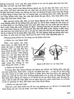
Working
pattern
0
Three shifts of
8
hours, 5 days per week
0
Tea breaks of 24 minutes per shift
Data
for
week
0
15 breakdown events totalling 43 hours
0
die changes averaging
4
hours each per set-up and changeover
0
15 500 units produced, plus
80
units scrapped, plus 150 units requiring
rework
0
Allowed time as planned and issued
by
production control for the five
jobs was 52 hours, including 15 hours for set-up and changeover
OEE
for
week
Loading time
=
attendance
-
tea breaks
=
120
-
6
=
114 hours
Downtime
=
breakdowns
+
set-ups and changeovers
=
43
+
20
=
63 hours
Availability
=
-
63
=
44.7%
114
Actual press running time (uptime)
=
120
-
6
-
43
-
20
=
51 hours
Allowed press running
time
=
52
-
15
=
37 hours
37
51
Product input (units)
=
15
500
+
80
+
150
=
15 730
Performance rate
=
-
=
72.5%
Quality
(first
time) product output (units)
=
15
500
Quality rate
=
-
tz
;i:
-
-
98.5%
OEE
=
0.447
x
0.725
x
0.985
=
31.9%
The TPM improaement plan
85
Data
for
fouiv-week period
Over a recent four-week period the following
OEE
results were obtained:
Week OEE
=
Availability
x
Pevformance
x
Quality
("/.I ("/I
rate
(Yo)
rate
(YO)
9
44.6
=
65.0
X
70.0
X
98.0
2 43.8
=
58.0
X
77.0
X
98.0
3 36.7
=
47.0
X
80.0
X
97.5
4
31.9
=
44.7
X
72.5
X
98.5
Average
39.4
=
53.7
X
74.9
X
98.0
Best
of
best OEE and potential benefit
The best of best
OEE
can now be calculated. In addition, if the hourly rate of
added value is taken to be
€100,
the annual benefit (45-week year) of moving
from the current average
OEE
of
39.4
per cent to the best of best can be found.
Best of best
OEE
=
availability
x
performance
x
quality
=
65.0
x
80.0
x
98.5
=
51.2%
Potential loading
hours
per year
=
114
x
45
=
5130
At
39.4%
OEE,
value added per year
=
0.394
x
5130
x
€100
=
€202 122
At
51.2%
OEE,
value added per year
=
0.512
x
5130
x
€100
=
€262 656
Therefore, a benefit of
€60 534
is possible by consistently achieving best of
best through tackling the six losses
using
the nine-step
TPM
improvement plan.
Step
3
Assessment
of
the
six
big
losses
The importance of understanding and tackling the six big losses cannot be
over-emphasized! They were listed in Chapter
3
and illustrated by the iceberg
analogy in Figure
3.14,
repeated here
as
Figure
5.5.
The six losses are
as
follows:
0
Breakdowns
e
Set-up and adjustment
0
Idling and minor stoppages
0
Running at reduced speed
0
Quality defect and rework
0
Start-up losses
These are elaborated in Figures
5.7-5.12
in terms of the relationship
of
these
losses to the
OEE.
Figure
5.6
shows the losses as
a
fishbone cause and effect diagram. This
formula is used by the
TPM
core team
as
a
brainstorming
tool
to list
all
possible causes and reasons for each
of
the six
loss
categories.
We
will
develop
a
detailed definition in later chapters regarding the
four
levels of control referred to under each of the
six
losses in Figures
5.7-5.12.
However, in order to give an early indication
a
definition
is
as follows:
86
TPM-A
Route
to
World-Class Performance
Outside services
Maintenance o/head
measure
Figure
5.5
True cost
of
manufacturing: seven-eighths hidden
Availability
x
Performance
X
Quality
rate rate rate
_____+/-
/ +
=if
-/
_7/
Figure
5.6
Factors in overall equipment effectiveness
Level
2
Milestone
1
after piiot/roll-out activity: 12-18 months
Level
2
Level
3
Build capability: 12-18 months later
0
Level
4
Refine best practice and standardize: 6-12 months later
(P-M
prize level)
Strive for zero:
3-5
years from roll-out launch
The
TPM
improvmt
plan
87
Level
I
Combination
of
sporadic and chronic
breakdowns
Sigrufcant breakdown losses
BM
>
PM
No
operator
asset
care
Unstable lifespans
Equipment weaknesses
not
recognized
Level 2
1
2
3
4
5
6
1
2
3
4
5
6
Level
3
Tune-based maintenance
PbbBM
Breakdown losses less than
1%
Autonomous maintenance activities
well established
Parts
lifespans lengthened
Designers and engineers involved
in
higher-level improvements
1
Chronicbreakdowns
2
Breakdown losses
still
significant
3
PM=BM
4
Operator asset care implemented
5
Parts
lifespans estimated
6
Equipment weaknesses well acknowledged
7
MaintainabiLity
improvement applied
on
above pints
Level
4
1
Condition-based maintenance established
2
PMonly
3
Breakdown losses from
0.1
%
to zero
4
Autonomous maintenance activities stable
and refined
5
Parts
lifespans predicted
6
Reliable and maintainable design developed
~~~
BM Breakdown Maintenance
PM
Predictive Maintenance
Figure
5.7
OEE
assessment:
breakdom
losses
Level
1
1
No
contml: minimum involvement by
operators
2
Work procedures disorganized: set-up and
adjustment time varies widely and randomly
Level
3
1
Internal
set-up operations moved
into
external set-up time
2
Adjustment mechanisms identified and
well understood
3
Error-umofina introduced
kvel2
1
Work
procedures
organized,
e.g. internal
and external set-up distinguished
2
Set-up and adjustment time still unstable
3
Problems
to
be
improved
are
identified
he1
4
1
Set-up time less
than
10
minutes
2
Immediate product changeover by
eliminating adjustment
Figure
5.8
OEE
assessment: set-up and adjustment losses
The improvement cycle in
TPM
starts
from
an
appreciation
of
what the
six
big losses are
and
proceeds
through
problem
solving
to the establishment
of
best practice routines. Eluninating
the
root causes
of
the
six
losses
is
tackled
in Step
9
of
the
TF'M
improvement plan.
Finally, Figure
5.13
shows a
summary
of
the
loss
categories with improve-
ment strategy examples.
88
TPM-A
Route
to
World-Class
Perfmmance
Level
1
Losses
from minor stoppages unrecognized
and
unrecorded
1
Unstable
operating
conditions due
to
2
fluctuation
in
frequency and location of
losses
LRvel3
All
causes of minor stoppages
are
analysed;
all solutions implemented
1
Level
2
Minor stoppage losses analysed
quantitatively by: frequency and lcmtion
of occurrence; volume lost
Losses
categorized and analysed; preventive
measures taken
on
mal
and error basis
L.evel4
Zero minor stoppages
(unmanned
operation possible)
Figure
5.9
OEE
assessment:
idling
and minor stoppage losses
Level
1
Level
2
1
Equipment specifications not well understod 1 Problems related to
speed
losses analysed:
2
No
speed
standards (by product and
2
Tentative
speed
standards set and
3
Wide sped variations across shifts/operators
3
Speeds
vary slightly
mechanical problems, quality problems
machinery) maintained by product
Level
3
Level
4
1
Necessary
improvements being implemented
1
Operation
speed
increased
to
design
speed
or
beyond
through
equipment improvement
2
Speed
is set by
the
product. Cause and
2
Fmal
speed
standards set and maintained by
effect relationship
between
the
problem product
and the precision
of
the equipment
3
Zero
speed
losses
3
small
speed
losses
Figure
5.10
OEE
assessment: speed losses
Level
I
1
Chronic quality defect problems
are
1
Chronic
quality
problems quantified by:
details of defect, frequency; volume lost
2
Many reactive and unsuccessful remedial
2
Losses
categorized and
reasons
explained;
preventive measures
taken
on
trial
and error
basis
neglected
actions have
been
taken
Level 3 Level 4
1
AU
causes of chronic quality defects
1
Quality
losses from
0.1%
to
zero
analysed;
all
solutions implemented,
conditions favourable
defects under study
2
Automatic in-process detection
of
Figure
5.11
OEE
assessment: quality defect and
rework
losses
The
TPM
improvemmt
plan
89
Level
1
Start-up losses
not
recognized understood
or recorded
1
2
hvel3
Process
stabilization
dynamics understood
1
and improvements implemented
2
Causes
due
to
minor stops
aligned
with
start-up losses
Lael
2
Start-up losses understood
in
terms
of
breakdowns and
changeovers
Start-up losses
quantified
and measured
Lael
4
Start-up losses minimized
through
process
control
Remedial actions
on
breakdowns, set-ups,
minor
stops
and idling minimize
start-up
losses
Figure
5.12
OEE
assessment:
start-up
losses
1
hprovement strategy examples
1
Improve detection
of
conditions contributing to
this,
spot problems
early.
Idenbfy in/outside work and organize/standardize.
Idenw
unnecessary
adjustments
and
eliminate.
Use
P-M
analysis. Cleaning
will
probably
be
a key factor.
Idenbfy
speed,
capability/capacity
through
experimentation. Speed
up
process to
maw
design
weaknesses.
Use
P-M
analysis to idenq
contributory factors.
Classlfy
causes
and
develop countenneasures,
including
standard
methods to reduce
human
error.
Establish key control parameters, minimize number of variables,
Breakdowns
Set-up losses
Minor stops
Reduced
speed
WtY
losses
Start-up
losses define standard
settings.
Figure
5.13
Reducing/eliminating
the
six
losses
5.2
Condition
cycle
Step
4
Critical assessment
The
aim
here
is
to assess the equipment production process and to agree the
relative criticality of each element.
This
will
enable priority to be allocated for
the conditional appraisal, refurbishment,
future
asset care and improvement
of those elements most likely
to
have
an
effect
on
overall equipment
effectiveness.
The approach
is
to
review the produdion process
so
that
all
members of
the team understand (probably for the
first
time!) the mechanisms, controls,
material processing and operating methods. Operators and maintainers must
be involved
in
idenhfyvlg the most critical parts of the process
from
their
own
perspective.
90
TPM-A Route to World-Class Performance
The important components and elements of the process, machine or
equipment are identified: some typical examples are electrics, hydraulics,
pneumatics, cooling systems and control systems. Each of these elements is
assessed in terms of criteria such as the following:
Safety
If this component was in poor condition
or
failed, what would be
the impact on safety due to increased risk of injury?
Availability
If this component was in poor condition or failed, what
would be the impact on the availability
of
the equipment, including set-
up and the need for readjustment of equipment settings?
Performance
What impact does this component have on the cycle time
or
processing capacity of the equipment when it is available to run?
Quality
If this component were in poor condition or failed, what impact
would it have on product quality at start-up and/or during normal
production?
Reliability
What impact does the frequency with which this component
fails have on the overall criticality of the equipment?
Maintainability
What impact does this component have on the ease of
maintaining or repairing the equipment?
Environment
If this component was in poor condition or failed, what
would be the impact on the environment due to emissions, noise, fluid
spills, dust, dirt, etc.?
Cost
If
this component was in poor condition or failed, what would be
the impact on total cost, including repair and lost production?
Total
The sum of the rankings for each component.
The significance of each of the criteria is assessed and allocated a score according
to impact on the process:
1
=
no impact,
2
=
some impact,
3
=
significant
impact.
A
typical matrix form for recording process elements and criteria scores is
shown in Figure 5.14. The right-hand (totals) column enables priority to be
applied to those elements most affected. This is further illustrated in Figures
5.15 and 5.16.
The main outputs from the critical assessment process are that it:
starts the teamwork building between operators and maintainers;
results in a fuller understanding
of
their equipment;
provides a checklist for the condition appraisal;
0
provides a focus for the future asset care;
highlights weaknesses regarding operability, reliability, maintainability.
The critical assessment matrix provides the basis for understanding not just
the most critical components but also those which contribute to special loss
areas. For example, high scores on
S,
M
and
R
indicate components which
have a high impact on safety, are unreliable and difficult to maintain.
A
score
of
6 or above on these three is an accident waiting to happen.
Other useful subsets include:
CRITICAL
ASSESSbIENT
O\
era11 equipment effectik-mess
A,
I'
and
Q
East.
of
use
P,
Q
and
R
h
1'1
in tai
n
a hi1
i
t
J
M,
C
and
R
Em
ironmentcil rish
E,
h.1
and
R
Reliabilit!.
A,
I'
and
R
Re\
ising those components \vith
a
high impact on q~ialit!.
is
a
good
starting
point for quality maintenance activities. Providing
the
assessment
is
applied
consistentlj,
it
can
also
be
used
to
establish
basic
maintenance strategies
such
as
condition based
(P
=
3+)
or run to failure
(C
=
1,
h4
=
1,
A
=
3).
These cm
then
be
refined as asset care routines are introduced
and
iniproL
ecl.
Step
5
Condition appraisal
The
objective
liere
is
to
make
LIS~
of
the same critical assessment elements
m~l
components in order
to
assess
the
condition
of
equipment and to identifj
the refurbislmient programme necessarj.
to
restore the equipment to maximum
efkcti\,eness.
92
TPM-A
Route
to
World-Class Performance
Sketch the machine process:
make sure that you know how it
functions
Identify the components to the
level
of
reulacement
uarts
Subassembly
+
Component
Assess each against the headin
of
safety, availability, etc. and
total to agree priorities
Figure
5.15
Stages
in
critical assessment
CRITICAL
ASSESSMENT
Where
S
=
Safety
R
=
Reliability
1
=
Noimpact
A
=
Availability
M
=
Maintainability 2
=
Some impact
P
=
Performance
E
=
Environment
3
=
Significant impact
Q
=
Quality
c
=
Cost
Figure
5.16
Completed critical assessment matrix
The
TPM
improvement
plan
93
Each heading will have been subdivided
as
necessary:
for
example, the
electrical section may contain power supply, control panels, motors and lighting.
Under each
of
the subdivisions
of
the equipment being studied, four
categories should be established:
Satisfactory
0
Brokendown
0
Needs attention now
0
Needs attention later
An
example
of
the outcome
of
a condition appraisal study
is
shown in Figure
5.17.
The key point
of
the condition appraisal
is
to put each square centimetre
of
the equipment under the microscope and assess whether its condition
is
‘as new’
or
’as
required’. Make
sm
also
that
you
look inside the machine,
so
remove
all
panels.
This
is
not just a broad, superficial look
-
on the contrary,
it
is
being obsessive about attention to detail.
As
such, the condition appraisal stage must include a deep clean
of
the
equipment.
Step
6
Refurbishment
The
objective
of
the refurbishment programme
is
to set up a repair and
replacement plan, based on the condition appraisal, and indicating the
resources
needed. Getting the equipment back to an acceptable level
is
a prerequisite to
the pursuit
of
ideal conditions.
The plan will provide a detailed
summary
of
actions to be co-ordinated by
the team, which
will
include:
0
dates and timescales
0
resources (labour, materials, time)
0
cost estimates
responsibllities
0
control and feedback (management
of
change)
A
typical summary table of refurbishment
costs
and man-hours required
for
a group
of
critical machines
is
shown in Figure
5.18.
The chart in Figure
5.19
gives details of action required on a specific item
of
equipment. It allocates responsibility
for
the various tasks and nominates
individuals to carry out the work; it also embodies
a
simple visual indication
of
work progress.
The refurbishment programme
is
concerned not just with clearly idenaable
repair work, but
also
with the many small weaknesses identified by the
condition appraisal, including
cleaning
and
CAN
DO
approach, such
as
missing
bolts, leaks, temporary repairs and over/under-lubrication, and it highlights
critical points for regular attention.
94
TPM-A
Route
to
World-Class Performance
I
Condition appraisal
-
Top
sheet
Machine
No
Date installed
Commissioned
Warranty ends
Location code
Plant priority
Generic group
PO
number
Common
Equipment
VM56694
20.07.9
1
01.08.91
01.08.92
K19
High
RH FlDoor
Assy
06 19862
Description
Marker
Manufacturer
Serial No
Marker’s No
Equipment Status
Equipment
Availability
RH front door
Hinge re-
inforcement co
welder
ESTIL
0766/01/00
Operational
Night
&
Day
General statement
of
reliability
~ ~~ ~~~~
I
Condition Appraisal lOf3
I
Machine description
1
Asset No:
1
Year
of
purchase
I
Appraisalhv:
hine No:
I
Location:
I
Apprais
The access to the
-
-
2
-
-
Appraisal
rating
by
sub
asset
Electrical
A
-
Power supply
to
machine
B -
Panel
D
-
Control circuits
E
-
Motors
F
-
Machine lighting
A
-
Spindle housings/Gearboxes
-
Seals
B
-
Slideways/Tables
-
Workpiece
-
Toolholder
C
-
ScrewsRamdSlined Shafts
D
-
Pneumatics
Figure
5.17
Example of condition appraisal study
The
TPM
imprmemenf
plan
95
848
879
SUMMARY
OF
TOP
20
CRITICAL
MACHINES
-Refurbishment
programme
Devlieg 60 17 760 17 820 17 212 229
No4Mill
85
-
85 I1
40
51
Snowgrinder
I
250
1
10600
I
10
850
I
14
I
10
1
24
I
I
871
1
6517-5
925
I
847
1
Devlieg
I
190
I
2760
I
2950
I
24
1
122
I
146
1
CNC650C-Axis 3330 230 3560 28 40 68
I
926
I
858
1
Hydro540
I
160
I
8270
I
8430
I
21
1
4
I
25
I
CNC
65OC-AXIS 190 790 980 17
40
57
II
Figure
5.18
Refurbishment
example
for
a
group
of
machines;
how
costs
can
be
spread
96
TPM-A
Route
to
World-Class Performance
Fill in fourth
segment when
refurbishment
has
Fill in first
a refurbishment action
is
defined
@
Fill in third
segment
when action
1
e
segment when
a
~~~~~;ecwoh"ed,
has been and responsibility is completed been tested
flagged is given
CO,
Mig Welding
WC:
Labour costs:
2
x
16 hours
=
32 hours
at
515.00
=
1
x
13
hours
=
13
hours at E14.00
=
Total
labour
-
Parts:
New seals
to
clamp cylinder
6 PX leads
-
Water
flow
gauge
-
New air ducting
-
Water pressure gauge
-
Total
parts
-
Total
Mig Welding
M/C
-
-
- -
-
-
-
-
-
-
f480
f182
t662
E15.00
560.00
E10.00
No
cost
E113.00
S198.00
t860.00
Figure
5.19
Refurbishment
example
for
a
specific machine
The
TPM
improvmf plan
97
Hydraulic Electrical
Step 7Asset care
Once refurbishment
of
an item of equipment has been carried out, a
future
asset care programme must be defined to ensure that the machine condition
is
maintained. It is therefore necessary to establish:
cleaning and inspection routines
checking;
and condition monitoring methods and routines
planned preventive maintenance and service schedules
For each of these we must develop:
0
It
is
important to distinguish between natural and accelerated deterioration.
In
the course of normal usage,
natural
deterioration will take place even
though the machine
is
used properly.
Acceluafed
deterioration arises from
outside influences. These are
equipmmnt-based,
i.e. failure to tackle the mot
causes
of
dust,
dirt
and contamination; and
operutor-based,
i.e.
Mure
to
maintain
basic conditions
such
as
cleaning, lubricating and bolting, and
also
human
operational errors.
Figures 5.20 and 5.21 show how the care of assets may be broken down
into elements which reflect the first
three
steps
of
the conhtion cycle: a-iticality,
condition and refurbishment. Figure
5.22
illustrates the relationship between
operational and technical aspects of asset care. Some key points for
consideration in asset care are shown in Figure 5.23.
The question of
training
is
developed fully in Chapter
7,
but some key
approaches are dustrated in Table
5.1.
A
training
schedule form
is
shown in
Figure 5.24.
This
schedule
is
completed through a series
of
single-point, on-
the-job lessons.
A
practical example of daily cleaning and inspection
is
gven in Figure
5.25.
This
shows the checks to be made in
a
MIG
welding cell for each
shift
during the working week, and records
all
the daily checks made by the
operators.
A
material usage
dwt
first developed to highhght loss measurement
improvements to make each task easier
visual techniques to make each task obvious
training
to achieve consistency between
shifts
coohg
Mechanical
Bearings
Fasteners
Drivers
-
Fdter~
-
Motors
-oil
-
Fuses
-
Cmlmt
-
pipes
Figure
5.20
Stages
in
asset
care
98
TPM-A
Route
to
World-Class
Performance
Hoses
Hydraulics
n
Shaft Flange
seals brushes
O-rings Gaskets Valves Motors Sensors
Effect on process effectiveness
I
Maintenance policy definition
I
Figure
5.21
Breakdown
of
asset care for hydraulics maintenance
Operational Technical
\
condition Servicing
/
and
Clean
/
performance
i
Inspect
i
Thermometer
Apple a day Injection needle
Figure
5.22
Relationship between operational and technical aspects
of
asset care
(see also Figure
3.4)
For each task, make it:
Eusy,
by simple improvements
Obvious,
using visual techniques
Consistent,
by effective training
Figure
5.23
Key points
in
asset care
The
TPM
improvement
plan
99
Table
5.1
Role
of
training
in
asset
care
~ ~~ ~~ ~ ~
Technique
Learning
points
1
rnprouemen
ts
~
Training
Cleaning
Inspection
Checking
Condition
monitoring
Planned
preventive
maintenancc
Servicing
Accel eratcd
deterioration
Cleaning
is inspection
What is
the
effect?
Check
condition
Check performance
What
arc
the
sip?
Using
our
serws
Using instruments
What
is
to be donc?
How
do
we
do
it?
Who and when?
How
do we
manage
it?
Highlight
vmerability
Make it
easy
Provide tooLs/equipment
Establish
standards
Establish pararncters
Makc change obvious
Make detection
easy
Provide tools/equipmcnt
Make
it
accessible
Make
it
maintainable
Clear rcsponsibility
Clear
instructions
Video
Singlepoint
lessons
lessons
Singlepoint
hbuction
Singlepoint
lcssons
is
now incorporated as
a
routine part
of
asset care in
Figure
5.25.
The
key
point
is
that the operators and maintainers have developed these asset care
routines on the basis that
’If
it’s
my
idea,
1
~7ill
stick with it’.
The ninestep improvement plan provides a comprehensive analysis toolbox
capable
of
reducing sporadic losses to zero, providing
the
appropriate
infrastructure
is
in place.
This
infrastructure must include a continuous drive
to reduce chronic
losses
by striving for
optimum
conditions. Not only does
this keep people motivated to
carry
out the essential routine tasks, it provide
progressively higher company competence to direct towards improved
customer services.
The progressive implementation
of
front-line asset
care
and preventive
maintenance provides the improvement zone partnership to deliver such
improvement.
Lf
the ninestep improvement plan provides the answer
to
what
is
required, then the improvement zone implementation process provides
the
answer to
how
it
is
to be delivered. The
how,
where and when
of
this
is
part
of
management’s role
in
’creating the environment’ for
TPM
(discussed
in
Chapter
8).
5.3
Problem prevention cycle
Step
8
Best practice routines
Following the restoration
of
cquipment and development
of
asset
care,
thc
next step brings together all
of
the practices developed
for
operating,
TOTAL
PRODUCTIVE MAINTENANCE PROGRAMME
RIH FKONT
DOORLINE
MIG
WELDTNC CELL
1
T Foley
Team
Leade,:
.
,
+
0
0
Team Check
member's
air
name gauge
I
A
Sefton
I
B
Gallagher
I&
M Lawton
N
Melling
Check Change Clamp
CO,
C02 check
Wise Wire
OPERATOR
TRAINING SCHEDULE
Air
&
water
leaks
Torch
check
Competent
in
a
process
CaiTied
out
process
Trained
in
proccduses
by maintenance
Able
to
train
0
others
I
I
Figure
5.24
Training
schedule
form
Shift
Change CO,
wire
Ckak
pressure
setting
mling
Check
table
8:
Cherk C02
wire
reel
&
spare
X
Check
clamp
head
secnrity
X
k
=heck
for
air
&
water
leaks
rop
UP
anti
spatter
fluid
3eck
torch
&
mess
,0mity
iemove
ihroud
and
:lea0
k
3erk
smog
log
light
is
)n
<erord
&
eset
cycle
nunter
Sheck
part
on
hadow
hard
lecord
scrap
avel
1
X
:ecoid
rework
:vel
Sign-