Theory Design Air Cushion Craft 2009 Part 3 pptx
Bạn đang xem bản rút gọn của tài liệu. Xem và tải ngay bản đầy đủ của tài liệu tại đây (2.36 MB, 40 trang )
66
Air
cushion theory
2.4
Static
air
cushion
characteristics
on a
water
surface
Static
hovering performance
of SES on
water
The
various shapes
of
mid-sections
of
sidewalls
are
shown
in
Fig.
2.16;
a
typical
one
is
figure
(a), namely sidewalls with perpendicular inner
and
outer walls near
the
water
surface.
The
craft
total
weight
is
supported
by a
combination
of
cushion
lift
and
buoyancy
of the
sidewall, which
can be
expressed
as
TT/
„
O
I
1
J7
i^
|
">
J
"7'\
W
—
p
c
b
c
+
2y
Q
y
w
(2.27)
where
Wis
the
craft
weight (N),
p
c
the
cushion pressure
(N/m
2
),
S
c
the
cushion area
(m
2
),
V
G
the
volumetric displacement provided
by
each sidewall
(m
3
)
and
y
w
the
spe-
cific
weight
of
water
(N/m
3
).
According
to
Archimedes' principle,
the
relationship between cushion beam, inner
and
outer drafts
and
width
of
sidewalls with
different
shape
can be
determined
by the
following
expressions
and
those
in
Fig.
2.16:
S
c
=
B
c
l
c
(2.28)
t
0
~
t
{
=
p
c
/y
w
(2.29)
where
t
0
is the
outer draft
of
sidewalls (m),
t
{
the
inner draft
of
sidewalls (m),
/
c
the
cushion length (m),
B
c
the
cushion beam
(m) and
w
the
calculating width
of
sidewalls
(m).
The
inner sidewall draft gradually reduces
as
lift
power
is
increased
and
cushion
air
will
leak from under both sidewalls once
the
cushion pressure exceeds
the
inner
sidewall
draft (Fig.
2.17),
as
well
as
under
the bow and
stern seals,
and
form
the
plenum type
of
craft, similar
to the
craft model
'33'
of
HSEI
and the US
Navy
SES-100B.
The
drag
of
this type
of
craft decreases dramatically
as
lift
power
is
increased.
The
outer draft
of
sidewalls,
t
0
,
is
dependent upon
the
lift
fan(s)
flow
rate
and the
inner draft,
/
;
,
is
dependent upon
the
cushion pressure
p
c
.
The air
leakage
from
the
(a)
(c)
(d)
Fig.
2.16
Sidewall thickness
on
various sidewall configurations.
Static
air
cushion
characteristics
on a
water
surface
67
Fig.
2.17
Air
leakage under
SES
sidewall
with
large
air
flow
rate, hovering static over
water.
cushion
at the bow
(also
at the
stern),
can be
illustrated
as in
Fig.
2.18.
The flow
rate
of
an SES
hovering statically
on a
water surface
is
normally calculated using
the fol-
lowing
assumptions:
• The air flow is
non-viscous
and
incompressible.
• For
simplicity,
the
outlet
flow
streamline chart
can be
considered
as
Fig.
2.18
and
takes
the
actual
air
clearance
as
</>(z
b
-
t
t
)
because
of
considering
the
contraction
of
leaking
air flow,
where
z
b
is
expressed
as the bow
seal clearance, namely
the
ver-
tical distance between
the
craft
baseline
and the bow
seal lower tip.
<$>
is the flow
contraction
coefficient
at the bow
seal.
• The
distribution
of
static pressure
for
leaking
air flow is a
linear function.
As
shown
in
Fig.
2.18,
the
static pressure
of
leaking
air flow is
p
n
=
p
c
for
rj
= 0, but
while
rj
=
(z
b
-
t
{
)
<f>,
p
n
= 0,
where represents
the
ordinate with
the
original point
B
and
upward positive.
Thus
the
static
pressure
of
leaking
air flow at any
point
can be
represented
by
P,
=
P<V
-
W]
(2.30)
According
to the
Bernoulli theory,
the
horizontal
flow
velocity
at any
point
between
AB can be
represented
by
following
expression:
Q.5p
a
U:
=p
e
-
p
c
[\
-
O)
(2.31)
Fig.
2.18
Air
leakage under
SES
bow
seal
hovering static over water.
Air
cushion
theory
where
Urj
is the
leaking
air flow
speed
in the
horizontal direction.
It is
clear
that
the
flow
rate leaking under
the bow
skirt
can be
represented
by
then
a
=
M
=
2/3B
c
<f>(z
b
~
t
{
(2.32)
As a
consequence,
the air
cushion
flow for
craft
statically hovering
on a
water surface
is
equal
to 2/3 of
that
on a
rigid surface, because
of the
action
of
back
pressure
of
leaking
air.
This estimate
is
approximate,
but
realistic
and is
generally applied
as a
method
of
estimation
of the flow
rate
of an
SES, because
of its
simplicity
and the
difficulty
in
measuring
the
steady
flow in an SES on a
water surface.
By the
same logic,
the flow
leaking from
the
stern seal
can be
obtained
by
this method; consequently,
the
total
flow
for
craft hovering statically
on the
water surface
can be
obtained.
It is
useful
to
note
that
the
same reduction
in air
leakage rate also applies
to an
ACV
hovering over water rather than land.
The
static
air
cushion
performance
of
ACVs
on a
water
surface
The
difference
between
the ACV and SES for
static
air
cushion performance
is
that
the
sidewalls provide buoyancy.
The
typical static hovering attitude
of an
amphibious
ACV can be
seen
in
Fig.
2.19.
If one
neglects
the
reaction
of the
perpendicular com-
ponents
of
jets
flowing
from peripheral
and
stability nozzles (the value
of
which
is
small
in the
case
of
small skirt clearance with
a
bag-finger type), then
the
cushion
lift
can be
written
as
S
c
=
I
C
B
C
(2.33)
where
l
c
and
B
c
are the
cushion length
and
beam, which
can be
measured from
the
line
on the
plan
of the
water surface, which
the
lower
tip of
skirt
is
projecting
on.
From
Fig.
2.19,
it is
found that
the
craft
weight
is
equal
to the
weight
of
water dis-
placed from
the
depression;
for
this reason,
the
actual skirt clearance
is
equal
to the
Fig. 2.19
ACV
hovering static
on
water.
Static
air
cushion
characteristics
on a
water surface
69
vertical distance between
the
lower
tip of the
skirt
and an
undisturbed water surface.
Owing
to the
application
of bag and
finger
skirts
and the
improvement
in
perfor-
mance through development, skirt clearance
on a
water surface
has
decreased year
by
year.
One can
observe
that
the
skirt
clearance
on a
water surface
is
very small
on
mod-
ern
ACVs
and
sometimes
the
value
may be
negative
for
larger craft with responsive
skirts.
Therefore,
it is
suggested that cushion
air flow can be
calculated
by
plenum
chamber theory
or the
foregoing methods applied
to
SESs.
The
peripheral
jet
requires
much higher
air flow to
seal
the air
cushion
in the
case where
the
craft hovers with
a
significant
gap to the
calm
water surface.
It is
noted that
the
hovering process
for an ACV
with
flexible
skirt
is
more compli-
cated,
and is
shown
in
Fig. 2.20,
in
which
the
numbers
are
explained
as
follows:
1.
This represents that
the
craft
floats off
cushion statically
on a
water surface,
the
draft
of
craft
is
T
0
.
2.
Lift
fan
starts
to
operate,
but
owing
to the low
revolutions,
fan
pressure
is
low,
therefore
T <
T
0
.
Though
the
craft
is
partially supported
by air
pressure,
the
draft
of
the
buoyancy
tank
is
still larger
than
zero
to
provide
partial
support
of the
craft.
3.
Fans
speed
is
continuously increasing.
In the
case
of T = 0,
namely zero draft
of
the
buoyancy tank, then
the
weight
of the
craft
will
be
completely supported
by
cushion
lift.
4. The fan
speed
is
increasing further, pressure remains almost constant while
flow
rate
is
increased, thus
the
skirts begin
to
inflate.
A
positive
hull
clearance
h'
begins
to be
gained,
but
smaller than design hull clearance.
5.
The
hull clearance
is
equal
to
design value
h'
s
,
a
large amount
of
cushion
air is now
leaking under
the
peripheral skirt,
the
volume being dependent
on the fan
charac-
teristic
and
lift
power.
Fig.
2.20
Various
static hovering positions
of an
ACV.
70
Air
cushion
theory
The air
cushion characteristic curves
for
both ACV/SES
are
shown
by
Fig. 2.21 (the
calculation
in
detail
can be
found
in
Chapter
11,
Lift
system design), where
•
Hj-Q
represents
the
characteristic curve
of
lift
fans,
p
t
-Q
represents
the
character-
istic
of the air
ducting, i.e.
the
characteristic curve
of a fan at any
given revolution
minus
the
pressure loss
of flow in air
duct,
p
v
represents
the bag
pressure
of
skirts
a.ndp
t
~Q
also represents
the
characteristic
of the
bag.
•
P~Q
represents
the
characteristic
for
static
air
cushion performance, namely
the
relation between
flow and bag
pressure
at
various hovering heights, which
can be
obtained
by the
foregoing formula.
For
this
reason,
the
curve
p-Q
represents
the
relation between
the bag
pressure
and flow
rate
andp
t
-Q
denotes
the
total pressure
of
air
duct
(or
bag)
at
various hovering heights
and fan
revolutions.
The
intersection point
of
both curves represents
the
hovering height
of the
craft
at a
given
craft
weight
(a
given cushion pressure)
and any
given
fan
speed. Hence,
the air
cushion characteristic curve
for an ACV can be
described
as
follows
(also similar
for
an
SES):
1.
The
minimum
fan
speed
for
inflating
the
skirt
of an ACV
(similar
to the
hovering
attitude
4 in
Fig. 2.20),
will
be
that
at
which
the
total
pressure
of the
lift
fan
equals
the
cushion pressure
at the
zero
flow
rate.
At
this point
the
craft
weight
is
sup-
ported
by
cushion
lift
perfectly,
but
without having risen
from
the
static condition.
In the
case
of
zero
flow
rate
the
total pressure
of the fan is
equal
to the
total pres-
sure
of the
duct
bag and
thus
to the
cushion pressure.
2. The
factors necessary
for
hovering
the
craft,
i.e.
from
attitude
1
transient
to
atti-
tude
3, is
that
the
bottom
of the
buoyancy tank
has to
leave
the
water surface
in
order
to
exert
the
cushion pressure
to the
bottom
and
lift
the
craft.
At
MARIC
p,
H-Q
Fig.
2.21
Air
duct
and air
cushion
characteristics
curves
of
ACV/SES.
Flow
rate coefficient method
71
there
is
experience that
a
hole
for
take-off
has had to be
installed
in the
craft
bot-
tom or
skirt near
the
water surface (Fig. 2.22)
in
order
to
blow
off the
water
in the
cushion
in
order
to
exert
cushion
pressure
on the
bottom,
because
the
height
of a
skirt
of a
jetted
bag
type (say,
H > 1
m
for
medium-sized ACV)
is
always higher
than
the
cushion pressure measured
by the
water head (namely
p
c
< 0.3 m
H
2
O).
3.
The
minimum
fan
speed
of an SES for
static
hovering
can
also
be
defined, namely
the
condition
of
zero
flow is
equivalent
to the
situation that
the
inner draft
of
side-
walls
t, has to
equal
the
bow/stern clearance
and
also
satisfy
the
following
equation:
W=P
CO
S
C
+
y
io
y
where
P
c0
is the
cushion pressure, namely,
the fan
total pressure
at
given speed
and
zero
air flow
rate,
S
c
the
cushion
area,
at the
sidewall draft
for
zero
flow
from
bow
and
stern seals,
F
jo
the
displacement (volumetric)
of the
sidewalls
at
Wthe
weight
of
craft.
This
is the
same
draft,
the
necessary condition
for an SES
hovering
in
such
a
mode,
namely
the
cushion
air
just
blows
off
under
the
bow/stern skirt (not
under
the
sidewalls).
It
should
be
noted here that
it is
important
for
sidewall
craft
to
have
a
positive value
of
?j
(Fig.
2.16)
so
that
air is not
leaked under
the
sidewalls. Experience suggests that
t
{
should
be
15-20%
of
t
0
.
Below
15%
air
will
start
to be
lost under
the
keels
in
rela-
tively
small
sea
states, restricting performance.
SES may
also need deeper draft
and
t
{
at
the
stern
to
prevent propeller cavitation
or
water
jet
ingestion
of
cushion air.
Sometimes
a
fence,
or
keel extension
may be
installed
to
help solve this problem.
15
PIJWfate
coefficient
method
\
'
I
"
;.r;
{
The
relation between
the
cushion
air flow
rate
and
pressure
for
craft hovering
on a
rigid
surface
and
calm water
has
been derived. However,
the bag and finger
type skirt
with
a
small number
of
large holes
for
feeding
the air
into
the air
cushion
from
the
Take-off
hole
Fig.
2.22
Take-off holes
on an
ACV.
72
Air
cushion theory
higher pressure
bag is
improved
by the
arrangement
of a
larger number
of
small
feed-
ing
holes. This design improves
the
strength
of
skirt bags
by
reducing stress concen-
trations
and
thus
the
tendency
to
tear
after
fatigue
due to
operation.
The air
cushion characteristics
of
such skirts
are
closer
to
those represented
by
plenum
chamber theory. Moreover,
the
take-off performance
and
obstacle clearance
ability
is
improved,
therefore
the flow for the
take-off
to the
planing condition over
water
is not
such
an
important
parameter
as
concerned designers
in the
early stage
of
ACV/SES development.
For
this reason, rather than spend time
on
deriving
the
math-
ematical expressions
for
predicting
the
static
air
cushion performance,
we
take
the
flow
rate
coefficient
Q
as the
factor
to
represent
the
static
air
cushion performance
of
craft.
The
relation
for Q can be
written
as
(2pM
(2-34)
In
general,
we
take
the
values
of Q to be
[15]
:
Q
=
0.015
-
0.050
for
ACV
Q
=
0.005
-
0.010
for
SES
The
required value
of Q is
related
to the
following
performance factors:
1
.
craft
drag
at
full
or
cruising speed
on
calm water;
2.
take-off ability;
3.
seaworthiness;
4.
longitudinal/transverse stability
of
craft;
5.
resistance
to
plough-in, etc.
Acceptable
craft
performance
can
normally
be
obtained
if the
cushion
air
system
is
designed with
Q in the
range above.
The
quoted range
is
rather large when designing
a
large
SES or ACV and so it is
normally best
to
start with
the
lower value (suitable
for
calm water operation, medium-speed
craft)
and
then assess
the
additional
flow
required
for
items
2 to 5.
These
factors will
be
discussed
further
in
following
chapters.
As an
alternative, particularly
for
amphibious ACVs,
one
often
takes
the
skirt clear-
ance
of the
craft hovering
on a
rigid surface
as the
factor
to
characterize
its
hovering
ability
and so to
design
the
lift
system. This
is a
common
approach
of
designers
because
it is
easy
to
measure
the
skirt clearance
of an ACV
both
in
model
and
full-
scale craft. Although
it is not
accurate
for the
reasons outlined
in the
discussion
of the
various
air jet
theories above,
it is
easier
to
compare with other craft
(or
models).
Typically,
for
smaller amphibious
craft
the
following
relation
is
used:
Q
=
V
c
D
c
hL(rn/s)
where
V
c
=
v
(2/?
c
//?
a
),
the
cushion
air
escape velocity
(m/s),
p.
A
=
1.2257
kg/m
3
/9.8062
=
0.12499
(kg
m/s
2
)
=
(0.07656
Ib/ft
3
/32.17
=
0.00238
slug/ft
3
in
imperial units)
D
c
=
nozzle
discharge
coefficient (2.3.4
item
5),
D
c
=
0.53
for 45°
segment,
L =
peripheral length
of
cushion
at the
ground line
(m) and h =
effective
gap
height, typ-
ically
0.125
X
segment width,
or if it may be
assumed that segment width
is
approxi-
mately
h
c
/2.5
then
h =
0.05
h
c
.
Thus
The
'wave
pumping'
concept
73
>
c
(2.34a)
This relates
the
required
flow to the
escape area
and
should result
in a
small
free
air
gap
under
the
inflated segment tips
of a
loop
and
segment skirted craft over
concrete.
2.6
The
'wave
pumping'
concept
The flow
rate, calculated
by
equation (2.34),
may
only meet
the
requirements
of
skirt
clearance
for a
craft
hovering
on
calm water.
As a
matter
of
fact,
craft
often
operate
in
rough seas,
in
which
the
craft pitches
and
heaves. Therefore designers have
to
cal-
culate
the
vertical motion
of
craft
in
waves
so as to
determine
the
average required
flow;
this
will
be
demonstrated
in
detail
in
Chapter
8.
Here
we
introduce
a
concept [16], namely wave pumping, which deals with
the
extreme hovering attitude
of
craft
in
waves.
We
assume that
the
cushion
inflow
rate
of
craft
operating
in
waves
will
stay constant, namely
the
same
as
that
in the
static hov-
ering
condition. Thus
the
cushion
flow
changes
as the
volume occupied
by the
wave
which
is
passing through
the
craft
changes,
as
shown
in
Fig. 2.23.
Consequent
to
this,
the
cushion pressure
will
fluctuate
because
of the fluctuation of
cushion outflow while
constant
inflow
rate
and the
incompressibility
of
cushion
air
are
assumed. Thus,
the
motion caused
by fluctuating
cushion pressure
is
called
'wave
pumping'
motion.
To
simplify
the
calculation,
we
assume
as
follows:
•
Cushion
air is
incompressible.
•
Waves
are
simple sinusoidal waves.
•
Skirt clearances
at
bow/stern seals
are
constant, while
the
craft
operates
in
head
waves.
• The
wave peak
will
never contact
the wet
deck
of
craft.
• The
lowest edge
of the
cushion (i.e.
the
base line
of
sidewalls) coincides with
the
horizontal line
of
trough, namely
no air
leakage under
the
sidewalls.
Two
typical situations
for
wave pumping motion
of
craft
operating
in
waves
are
shown
in
Table 2.6.
In
fact
we may
assume that
the SES can
operate
in one of
three
following
modes.
First
operation mode
-
platforming
In
this mode
of
operation,
the ACV or SES
cannot respond
to the
waves, normally
short steep chop,
and so as
wave peaks pass through cushion pressure
is
raised,
and
Fig.
2.23
Platforming
of
SES
in
waves.
74
Air
cushion
theory
Table
2.6
Craft
operational
modes with respect
to the
wave pumping motion
Operation
mode
due
to
wave pumping
Mode
1
Mode
2
Running attitude
Platforming
Cushion volume constant
Cushion
over wave
crest
Air
blown
off
from
cushion
Craft
lifted
up
Cushion over wave
trough
Air
feed
to
cushion
to
fill
cavity
Craft drops down
as
a
trough passes,
the air gap
under
the
skirts increases
and
volume
flow
increases.
The
result
is a
rapid oscillation
in the fan
characteristic
and
vibration
felt
by
opera-
tors.
If
lift
power
is not
increased, skirt drag increases
and
speed reduces,
often
with
a
bow-down trim induced
and in
very short chop possibly
a
plough-in tendency.
In
very small
sea
states, small vibrations
can be
induced,
which
feel
rather
like driving
a
car
over cobbles, hence
the
effect
is
called 'cobblestoning'. Normally this only occurs
in
craft which have
a
cushion with high volume
flow
rate.
Second
operation
mode
-
constant
cushion
volume
If
the flow
rate
and
cushion volume
are
held constant, keeping
the
lift
power output
at a
minimum, then
a
definite
vertical acceleration
will
exert
on the
craft because
of
wave
pumping motion. Thus
the
maximum vertical acceleration
can be
derived under
the
action
of
pumping
as
follows:
(d^)
max
=
[7rv
2
]/[10x/
c
]
(2.35)
This calculation
is
approximate, because
a lot of
assumptions have been made.
In
par-
ticular,
the
heave
and
pitch motion
of the
craft
in
waves
and air
leakage around
the
sides
of
cushion have
not
been considered, therefore
the
calculation
is
very simple
and
does
not
demonstrate
the
seaworthiness quality
of the
craft.
It
does, however, indicate
the
acceleration which
will
occur
if the
craft
follows
the
wave
surface
profile,
where
no
reserve
lift
power
or
inflow
rate
is
available.
To
reduce
this,
it is
necessary
to
allow
the
skirt
to
respond
to the
waves, which
will
then allow
air
to be
pumped
out of the
cushion.
An
example calculation
for
this
is
given below.
The
aim of
this calculation
is to
help designers
to
consider
the
reserve
of
lift
power which
is
needed
to be
available
to
counteract
the
extreme motion
of
craft
operating
in
rough
seas.
Third
operation
mode
-
combination
of
first
and
second
modes
The
cushion pressure, cushion volume
and the
height
of wet
deck relative
to the
water
surface
are
changed together, namely
trading-off
both
the
foregoing motions.
In
prac-
tice
this
is the
mode which practical ACVs
operate
in.
Platforming
analysis
The first
mode
is
platforming, i.e.
the
cushion pressure
and the
vertical position
of the
wet
deck remain
constant,
then
the
vertical
acceleration
will
also
be
constant.
This
is
the
ideal operating attitude
of
craft
and
what
the
designer requires. However,
one has
The
'wave
pumping'
concept
75
to
regulate
the
lift
power
and
lift
inflow
rate
to
keep
the
cushion pressure constant.
This condition
is
also
the one
which
will
absorb
the
greatest volume
of
air;
therefore
we
will make
an
analysis
of
this
case.
When
the
craft moves along
the
jc-axis
for a
distance
of
dx,
then
the
change
of
water volume
in the
cushion
can be
expressed
by the
change
of
water volume
at the
bow/stern
of the
craft
as
shown
in
Fig.
2.23, then
dV=
B
C
[(HI2
+
h
f
)dx
-
(H/2
+
h
t
)dx]
(2.36)
where
H is the
wave height,
h
f
the bow
heave amplitude relative
to the
centre line
of
the
waves,
h
r
the
stern heave amplitude relative
to the
centre line
of the
waves
and
B
c
the
cushion beam. Thus
because dx/dt
= 0,
dV/dt
=
B
c
(h
f
-
/z
r
)v
where
v is the
craft velocity relative
to the
waves.
The
wave profile
can be
expressed
by
h =
(H/2)
sin a
where
a
=2nx/A,
thus
otf
=
o.
r
+
2nl
c
lA
where
h is the
wave amplitude,
/
c
the
cushion length
and
X
the
wave length. Therefore
dV
B
C
H
-7-
—
.
(sin
a
f
-
sin
a
r
)
v
B
C
H
[
.
/
27r/
c
\
. 1
=
—r—
sin
a
r
H——
—
sin
a
r
v
^
V
\
A-
/
J
£
c
//v
[/
2;r/
c
t
\
. .
2nl
c
]
.„
=
—^—
cos
—^
—
1
sm
a
r
—
sin
—r—
cos
a
r
(2.37)
2
L\
/i
/
/
J
In
order
to
determine
the
maximum instantaneous wave pumping rate,
we
take
the
first
derivative
of
function
d
VIdt
with respect
to a
equal
to
zero, then
17
2nl
,\
.
2nL
. 1
rt
cos
—:
1 cos
a
r
—
sm
——
sm
a
r
= 0
l\
A / A J
da
dr
2
This expression
can be
written
as
tan
a
r
=
(cos(27r/
c
/A)
— 1
)/sm(2nl
c
/A)
(2.38)
Substituting expression (2.38)
into
(2.37),
the
maximum
instantaneous
wave
pumping
rate
can be
written
as
(dV\
B
c
Hv
[7
2nl
c
1
\.
\/.
2
2nl
c
\/(
2nl
c
\1.
1
—T—
=—^—
cos-^
- 1
sma
r
-
sin
—^
/
cos
-^
- 1
sin
a
r
V
dt
/
max
2
L\
A
/
L\
A
//
V A
/J
J
76
Air
cushion
theory
so,
using
the
relation
sin
2
= 1
—
cos
2
f^p)
=
-B
c
Hv
sin
a=
-B
c
Hv
sin
a
r
(2.39)
\
o<
/
max
where
(dv/dO
max
is
the
maximum instantaneous wave pumping
rate
written
as
a
r
=
—nl
c
/A
For
instance,
for the
UK's SR.N5 hovercraft,
in the
case
of
)J2
=
l
c
= 9 m, H = 0.8
m,
v
= 35
m/s
then
(d
F/d?)
max
=
150
m /s,
i.e.
the
maximum power
due to the
wave pump-
ing is
172.7
kW. The
total
lift
and
propulsion power
is 735 kW, of
which about
30%
or 221 kW is
used
to
power
the
lift
fan.
It can be
seen, therefore,
that
the
lift
system
of
SR.N5
can
compensate
the
cushion
flow
rate consumed
by the
wave pumping
motion
at
this speed.
2.7
Calculation
of
cushion
stability
derivatives
and
damping
coefficients
In
this section
we
will
discuss
the air
cushion stability
and
hovering damping which
are
very important parameters concerning
the
longitudinal
and
vertical motion
of
ACVs hovering
on a
rigid surface. These parameters will greatly
affect
the
natural
heaving
frequency, seaworthiness
and
comfort
of
craft,
but are
only relative
to the
sta-
tic
air
cushion characteristics
of
ACVs.
For
this reason, these parameters
are
dis-
cussed
in
this chapter.
With respect
to the
SES,
the air
cushion stability
and
damping
are
also influenced
by
the
buoyancy
and
damping
force
of
sidewalls, because they
are
immersed
in the
water.
The
effect
of
sidewalls
will
be
discussed
at
greater length
in
Chapter
9,
though
of
course
it
is not
difficult
to
derive them
by
means
of the
methods demonstrated
in
this chapter.
We
take
the ACV
running over ground
as an
example
and
based
on
this
the
heav-
ing
motion
can be
illustrated
in
Fig.
2.24.
z
c
and
z
e
are
heaving displacement
and
veloc-
ity
respectively
and
z
e
,
z
e
,
denote
the
motion amplitude
and
velocity
of the
ground
plane, similar
to the
amplitude
for
waves.
The ACV can be
described
as an
elastic system with
a
spring
and
damper connected
parallel
to
each other. Strictly speaking,
the
spring
and
damping
coefficients
are
non-
linear
and
asymmetric,
i.e.
they
are
rather
different
for
upward
and
downward
motion.
As a first
approximation, assuming vibration movement with minute
dis-
placement,
the
motion
can be
considered
as
approximately linear.
Thus
an ACV
running
on a
rough ground surface
may be
considered equivalent
to
(=p
J
L
'
7
/
/
/ /
7
7
T
///
//////
Fig.
2.24
Heave
motion
of a
hovercraft
model
on
rigid
surfaces.
Calculation
of
cushion stability derivatives
77
a
vibration
system with
one
degree
of
freedom (only
the
heaving
motion
is
considered
here)
and the
frequency response
can be
shown
in
Fig. 2.25,
in
which
co
e
/co
n
denotes
the
tuning factor,
co
e
represents
the
encounter frequency, namely
the
exciting frequency
of
ground relative
to
craft,
co
n
is the
natural vibration frequency, i.e.
the
heaving nat-
ural frequency
of
craft,
and M
represents magnification factor, i.e.
the
ratio
of
heave
displacement
to
ground amplitude.
In
Fig. 2.25,
it can be
seen that
the
higher
the
damping
coefficient,
the
lower
the
magnification factor
in the
case
where
the
tuning factor
is
close
to
1.
In the
case
of
lower
tuning factor, then higher damping
coefficients
give higher magnification factor.
This means that
the
vertical motion
of
craft with
a
large damping
coefficient
will
be
violent
in the
case where
the
craft
run in
short waves
or on a
rough ground surface.
Therefore
the
damping
coefficient
is
very important
for
decreasing
the
vertical vibra-
tion
of
craft.
Before
discussing these problems,
we
prefer
to
introduce three typical
flow
modes
for
craft
in
heaving motion
as
shown
in
Fig. 2.26:
(a)
shows equilibrium
flow,
i.e. sta-
tic
hovering mode
of
craft;
(b)
shows
the flow
underfed, i.e.
the
instantaneous skirt
clearance
will
be
smaller
than
the
equilibrium skirt clearance
as the
craft drops
down,
consequently
the jet flow
cannot seal
the
cushion
air
causing some
air
leakage from
the
cushion;
(c)
shows
the flow
overfed, i.e.
the
instantaneous skirt clearance
will
be
larger than
the
equilibrium skirt clearance
as the
craft
lifts
up,
consequently more
air
flow
will
get
into
the
cushion
to fill up the air
cavity. These three modes
appear
alter-
nately
as the
craft heaves.
Calculation method
for
heaving stability derivatives
and
damping
coefficients
First
of
all,
the
profile
of the
skirt
is
assumed unchangeable
in the
case
of
deriving
the air
cushion stability derivatives
and
damping
coefficient.
This assumption
is
(=0.2
co
e
/co,,
Fig.
2.25
Frequency response
for
heave
motion
with
one
degree
of
freedom.
78
Air
cushion
theory
(a)
•?—7
7"
(b)
Q,
(c)
Fig.
2.26
Three
conditions
for
heave motion
of
ACV:
(a)
equilibrium;
(b)
underfed;
(c)
overfed.
reasonable
for a
conventional medium pressure
bag and finger
type skirt
for
small
perturbations.
A
responsive skirt with high deformability
may
have lower
effective
damping.
Regarding
the
effect
of
hovering performance
and fan and air
duct characteristics
on the
heaving stability
and
damping,
we
assume
as
follows:
1.
The
hovering performance
of the
skirt complies with
the
plenum chamber formula.
2.
The flow air in the
cushion
is
incompressible.
3.
In
order
to
compare
the
calculation value with experimental results,
the
rigid
ground surface
is
considered
to
heave vertically,
and we
keep
the
craft
hard struc-
ture unmovable.
Then,
according
to the flow
continuity
equation,
we
have
dm
—
dt
d
dt
=
-rp
=
p
a
dV
dp
a
dt dt
(2.41)
Calculation
of
cushion
stability
derivatives
79
where
Q
0
is the
outflow
rate
from
the
cushion
(m
/s),
Q
{
the
inflow
rate into
the
cush-
ion
(m
3
/s),
Fthe
cushion volume
(m
3
),
m the
mass
of air in the
cushion
(Ns
2
/m)
and
p.
d
the air
density
(Ns
2
/m
4
).
Considering
the
cushion
as
incompressible, thus
dpjdt
= 0.
Then
Q
0
=
\i/A,(2pJp
&
f
5
where
A
t
is the
area
of air
leakage (m).
Now
Q
{
can be
written
as
a = fiio
where
Ap
c
=
p
c
—
p
c0
,
p
c()
is the
cushion pressure
at
equilibrium
feed
mode
and
p
c
is the
instantaneous cushion pressure.
If
we
assume that
z, the
displacement
of the
ground,
is
upward positive
and
there
is
no
rotation
of
ground
motion,
then
dV/dt
=
-S
c
z
and
S
c
=
A
m
+
(cUj/dz)
z =
4
0
-
h
where
S
c
is the
cushion area
(m ),
A
i0
the
area
of air
leakage
at
equilibrium
flow
mode
(m
2
)
and 1 the
peripheral length
for air
leakage
(m).
Then substitute
the
foregoing
equation into (2.41), which gives
-S
c
z
=
[Q
io
+
(30/3/0
4>J
-
y/G4
io
-
*i)
'
(2/>
c
/A/
5
or
s
-S
c
z
=
Q
l0
+
(dQ/dp
c
)
Ap^
-
i//A
io
(2pjp
a
+
y/l
2
(2p
c
/p
a
(2p
c
lp
a
)°'
s
term into
a
Taylo
then these expressions
can be
written
as
Extend
the
(2p
c
lp
a
)°'
s
term into
a
Taylor series
and
neglect
the
nonlinear terms,
and
0.5
3/?
c
\
yO
a
/
then
(2.42)
=
-A
Pc
-A
Pc
+
(2.43)
We
2
PcO
«0
where
/z
0
is the
skirt clearance
at
equilibrium
flow
mode (m),
Q
t0
the
inflow
rate
at
equilibrium
flow
mode
(m
3
/s)
and
p
c0
the
cushion pressure
at
equilibrium mode
(N/m
2
).
Equation (2.43)
can be
written
as
K,
Ap
c
=
-K
2
z
-
K
3
z
or
4>
c
=z-z
(2.44)
SO
Air
cushion
theory
where
K
3
=
vl(2
P
M°-
5
=
Q
0
/h
0
(2.45)
Assume
the
cushion pressure
is a
linear function
of
heaving amplitude
and
velocity,
then
Using
the
equivalent terms
of
(2.46
and
2.44),
we
have
Go
z
—
2p
c0
where
d/?
c
/3zis
the
velocity derivative
of
/?
c
with respect
to z,
i.e.
the
cushion damping
coefficient,
dp
c
/dz
the
derivative
of p
with respect
to z,
i.e. heaving stability derivatives
and
dQ/dp
c
the
derivative
of
Q
due to the
characteristic curves
of
cushion
air
duct-fan
systems
with respect
to
p
c
.
Then
where
dQ/dH^
is the
slope
of the fan
characteristic,
if
//j
=
A +
BQ
+
CQ,
i.e.
2C0
dHj/dp
c
is the
slope
of the air
duct characteristic
and
dpjdp
c
the
derivative
of bag
pres-
sure with respect
to
cushion pressure, which
can be
calculated according
to
expression
(2.3).
It is
then
not
difficult
to
calculate
the
natural heave frequency without damping
and
heave
damping rate:
M
(2.49)
3z
2Mco.
y
withoul
damping rate
and M the
mass
of the
craft (kg).
where
co.
is the
natural heave frequency without damping
(s ),
£-
the
heaving
Calculation
of
cushion
stability
derivatives
81
Experimental
methods
for
heave
stability
derivatives
and
damping
coefficient
The
foregoing
formulae
can be
proved
by
experimental methods,
in
particular tests
using
ground excitation
(a
hinged base plate)
in
test skirt
box
equipment, then mea-
suring
the
time history
of
cushion pressure, vertical displacement
of the
ground plate,
total pressure
of
fans
and flow
rate,
z(t),
p
c
(t),
H-
}
(t),
Q(t),
as
shown
in
Fig. 2.27.
Typical test equipment
is
shown
in
Fig. 2.6. This uses
a 400 W
electric
motor
via
eccentric wheel
to
drive
the
ground plate
in
heaving
motion.
The
heave
amplitude
z(t)
can be
changed
by
changing
the
position
of the
eccentric wheel
and a
sliding linear
resistance
and
potentiometer used
to
measure
the
time history
of
displacement
of the
ground plate.
The
ground plate
will
move
in
simple harmonic motion, i.e.
the
eccentric wheel
moves
in
circular
motion
with
constant
angular velocity.
For
this
reason
the
variables
p
c
(t),
Hj(t),
0(0,
are
also
in
simple harmonic motion.
H
}
(t)
and
p
c
(t)
can be
measured
by
capacitance type pressure sensors.
The
following
physical phenomena
can be
observed during such tests:
• The fluctuation of fan
total pressure
is
small.
• As
shown
in
Fig. 2.27,
the
cushion
flow
forms underfed
mode
as the
ground
plat-
form
is
moved upward, i.e.
the
points
B, C
denote underfed
and
points
D, A
denote
overfed
flow
mode
with/>
dropping down.
• As
shown
in
Fig. 2.27,
the
p
c
(t)
precedes
the
z(f)
and the
phase lead
is e.
Heave
velocity
equals zero
at
points
A and C and the
heaving velocity reaches maximum
heave
displacement equal
to
zero
at
points
B and D.
Then
the
stability
coefficient
and
damping
coefficient
can be
written
as
-dpjdh
=
a/7
c
/az
=
-j
PcA
/z
m
=
A
PcC
iz
m
(2.50)
-8/7
c
/9/z
=
Apjwz
m
=
-Ap
c0
lcoz
m
(2.51)
B
and D
denote
the
maximum heaving velocity, while
A and C are the
maximum heav-
ing
displacement
z. In
addition because
of
simple harmonic motion
in
heave,
z can be
written
as
Fig.
2.27
Time history
of
cushion pressure
and
heave amplitude.
82
Air
cushion
theory
z
=
z
m
sin
co
t
Ap
c
=
Ap
cm
sin
(cot
+
s)
=
Ap
cm
sin cot cos
e
+
zf/?
cm
cos cot sin £
(2.52)
and
_
a/7
c
a/7
dp
c
sin cot +
-T
•
z
m
co cos cot
(2.53)
then
a/?
zJ/7
cm
sing
dp_
=
Ap
cm
cose
The
stability
and
damping
coefficient
can
then
be
obtained using equations (2.50),
(2.51)
and
(2.54)
from
measurements taken
on the rig
using known values.
Comparison
of
calculations
with
test
results
1.
A
comparison
of
calculations with test results
is
shown
in
Figs 2.28
and
2.29
and
it
is
found that
the
calculated values
are in
good agreement.
The
latter
are
higher
than
the
former, because
of the air
leakage
from
the
connecting
parts
of the flexi-
ble
skirts (the results
are
uncorrected).
The flow in
test
is
consequently larger than
the
actual value,
and the
calculation values
are
smaller than
the
test results.
2.
From
equation (2.47),
it is
found that because
dQ/dp
c
< 0 and
both
Q
0
> 0
and/?
c
> 0,
this means that
the
steeper
the fan
characteristic curve
(H
r
Q),
the
smaller
dQ/dHj
and the
larger
the
damping
coefficient.
3.
From
the
formulae,
one can see
that
the
heave stability
is
proportional
to flow
rate
and
inversely proportional
to
skirt clearance;
and
that
the
relation between
the
heave
stability
and the
characteristic curve
of
fan/air ducting
is
similar
to the
rela-
tion between
the
damping
coefficient
and the
characteristic
of
fan/air ducting,
namely
that mentioned
in (2)
above.
Calculation
of
cushion
stability
derivatives
83
100 150
z(mm/s)
/z
0
=4mm
«
f
=2050r/min
r=0.66s
Fig.
2.28
Comparison
of
p
c
between
the
calculated
and
experimental result
as a
function
of
heaving
velocity.
®
calculation
*
test results
n
f
=2Q50r/mm
10
h
0
(mm)
15
Fig.
2.29
Comparison
of
heave position derivative between calculations
and
measurements
as a
function
of
air
gap.
Steady
drag
forces
3.1
Introduction
ACVs
and
SESs create drag
forces
as
they move over
the
water
surface.
The
most
important drag components
are
those
due to
friction
with immersed components such
as
sidewalls, skirt, propellers, rudders
and
other appendages;
and
wave-making drag
from
the
moving cushion pressure
field and
sidewalls.
In
addition, momentum drag
due to
acceleration
of the air
used
for the
supporting
air
cushion,
and
aerodynamic
profile
drag
of the ACV or SES
become important components
at
higher speeds.
In
this chapter
we
will
outline
the
theory behind these drag components
and
describe methods
for
their estimation.
3.2
Classification
of
drag
components
The
method
of
calculating drag
forces
on an ACV or SES is
similar
to
that
for
pre-
dicting
the
drag
of a
planing
hull
or a sea
plane
before
take-off.
ACVs
and SES
also
generate spray drag, skirt
friction
drag
and
skirt inertia drag
in
addition
to the
water
drag components associated with
a
normal ship.
For
this reason drag calculations
are
more complicated than
for
other marine
craft.
Based upon calculation methods
for
predicting
the
drag
of a
planing hull,
the
prin-
cipal
author
and
colleagues
at
MARIC
have developed
a
methodology
for
predicting
the
drag
for
ACV/SES which
may be
summarized
as
follows:
•
First
of all we
obtain
the
total drag
from
model tests
in a
towing tank
and
some
other main components
of
drag
by
means
of
reliable
and
practical methods, e.g.
according
to the
Reynolds analogue theory
to
obtain
the
test results
in
wind tun-
nels
for
predicting
air
profile
drag.
•
Then
the
residual drag
of
models
can be
determined
by
deducting
the
main
components
of
drag which
can be
calculated individually,
from
the
total drag
of
the
model measurements.
According
to
Froude's analogue theory
we can
define
the
residual drag
of
full-scale
ships
from
that
of
models; consequently
the
total
drag
for a
full-scale ship
can be
3
Classification
of
drag components
85
obtained
by
adding
the
residual drag
of the
ship
to the
main components
of
ship drag
which
can be
determined
by
calculations.
In
general,
the
total drag
of
craft
can be
written
as
follows:
R
m
R
or
where
R,
dcv
is the ACV
total drag;
R
SK
the SES
total drag;
R
w
the
wave-making drag
due to the air
cushion;
R
d
the
aerodynamic
profile
drag;
R
m
the
aerodynamic momen-
tum
drag;
R
sk
the
skirt drag
for
ACVs
and
bow/stern seal drag
for
SESs;
R
swf
the
fric-
tion
drag
of
sidewalls;
R.
dp
the
underwater appendage drag (e.g. rudders,
air
ingestion
fences,
propeller brackets);
R
mw
the
hydrodynamic momentum drag
due to the
cooling
water
of
engines
and
R
a
the
drag
due to the
differential
air
momentum leakage
from
bow
and
stern skirts.
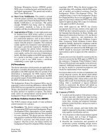
Fig.
3.1
shows
the
various components
of
drag
of the
SES-100A
built
in the
USA.
The
principal dimensions
and
parameters
of the
SES-100A
are LIB =
2.16,
p
c
/L
c
=
19.5
kgf/m,
v
max
=
76
knots.
The
following
sections
of
this
chapter outline
the
methodology
for
determination
of
each drag component listed above.
24
^
wave making drag
sidewall
drag
underwater
appendage
drag
air
profile
and
momentum drag
Fig.
3.1
SES-100A
drag
as a
function
of
Froude number.
Steady drag forces
33
Air
cushion
wave-making
drag
(RJ
Wave-making
drag generated
by a
pressure distribution
is a
classical theme
of
hydro-
dynamics, since
a
ship's hull
is
generally represented
by a
surface consisting
of a
vary-
ing
potential function which applies positive pressure
in the
forebody
and
suction
pressure around
the
stern
[8,17].
The
equivalent problem
for a
hovercraft
was
addressed
by
Newman
and
Poole
[18],
who
derived
a
calculation method
for
predicting
the
wave-making drag. They sim-
plified
the air
cushion
to an
equivalent rectangular surface with
a
uniform pressure
distribution
and
calculated
the
wave-making drag
as
. 7
PC-'
[(P
w
.g)\
(3.1)
where
Cl
= f
(F
r
and
and
R^
is the
wave-making drag
due to air
cushion, (N),
p
c
the
cushion pressure
(N/m
),
B
c
the
cushion beam, (m),
l
c
the
cushion length (m),
p
w
the
water mass density
(0.10177
-
0.1045)
(N
s
2
/m
4
),
g the
gravitational acceleration
(9.8066)(m/s
2
)
and
C
w
the
wave-making drag
coefficient
due to the air
cushion travelling
on a
waterway with
infinite
depth,
as
shown
in
Fig. 3.2.
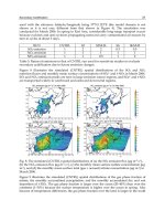
Figure
3.2
shows
that
as
cushion length
is
increased,
so the
primary hump
at
F
r
approx. 0.56 reduces. Craft with
IJB
C
in the
range
2-A
have
a
significantly
higher
drag
peak
at
F
r
approx. 0.33,
so
thrust margin
at
this speed should also
be
checked during
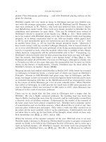
design. Figure
3.3
shows
the
variation
of
C
w
against
IJB
C
for
various
F
r
,
interpreted
from
Fig. 3.2.
It can be
seen that below
IJB
C
of
about
6, the
primary drag hump
at
F
r
0.56
begins
to
build
up.
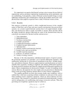
Figure
3.4
shows plots
of
C
w
vs
F
r
for
selected
IJB
C
,
taken from
Fig. 3.3.
It is
important
to
note here that wave-making
drag
is
proportional
to
p
c
and the
cushion width. Craft drag
can
therefore
be
significantly
reduced
by
increasing
craft
length.
This
was
used
successfully
by BHC in
stretching
the
SR.N6
craft
in the UK,
and the US
Navy
SES-100
to
SES-200.
In
fact,
the
wave-making drag
can be
defined
as
^w
^w
.
=
=
sin
a
(3.2)
P
C
S
C
W
where
a—a'
is the
average slope
of the
wave generated
by a
moving
air
cushion. This
is
most suitable
for a
cushion moving
at
high
F
r
,
generating
a
wave, rather longer
than
cushion length.
Meanwhile,
equation
(3.1)
can
also
be
written
as
~
C^vu
3)
v
Air
cushion
wave-making drag
87
BJl
c
=0.25
fi,//,=0.125
channel
width
greater
than
10/
f
and
infinite
depth
5.0
2.0 1.0 0.6 0.5 0.4 0.3
Fri=vl-Jgl
c
Fig.
3.2
C
w
plotted
against
F,\
for
constant
LJB^.
or
where
pjl
c
is the
pressure/length ratio
of
hovercraft.
As
mentioned above,
the
wave-making drag
is a
function
of
cushion length
to
beam
ratio, pressure
to
length ratio
and
Froude number.
The
cushion length/beam ratio
therefore
plays
a
significant
role
in the
craft performance.
Reference
19
also
offered
another
similar formula
for
estimating
the
wave-making
drag:
R
W
=
C
w
(4/?
c
W)l(p
v
g
/
c
)
(3-4)
where
/
c
is the
equivalent cushion length, i.e.
/
c
=
S
C
/B
C
,
S
c
the
cushion
area,
B
c
the
cushion beam
and
C
w
the
wave-making drag
coefficient
as
shown
in
Fig. 3.4.
It
should
be
noted that
it is
best
to use the
formula above together with formulae
Steady
drag
forces
channel
width
greater
than
10/
c
and
infinite
depth
8
l
c
/B
c
Fig.
3.3
Cushion wave-making drag coefficient
for a
rectangular
air
cushion over calm
water
against
L
C
IB
C
.
predicting
the
other components
of
drag also developed
by the
same authors, e.g.
when
one
uses
the
equation (3.4)
for
estimating
the
wave-making drag,
it is
better
to
use
this together with
the
other formulae
offered
by
ref.
19
for
estimating
the
seal drag,
sidewall water
friction
and the
residual drag
of
sidewalls, otherwise
the
user
may find
inconsistencies
in
calculation
of the
total resistance
of the
ACV.
Owing
to the
easy application
and
accuracy
of
Newman's method,
MARIC
often
uses Newman
and
Poole's data
for
estimating
the
wave-making resistance
of
craft.
It
is
evident
from
this work that
the bow
wave strongly interacts with
the
stern
wave.
The
lower
the
cushion beam ratio,
the
stronger
the
disturbance between
the two
compo-
nents. This causes
a
series
of
peaks
and
troughs
on the
resistance curve. With respect
to
water with
infinite
depth,
the
last peak appears
at Fr —
I/A/TT
=
0.56.
The
theory mentioned above
was
validated
by the
experimental results carried
out
by
Everest
and
Hogben
[20].
The
theoretical prediction agreed quite well with exper-
imental results except
at low
speed.
In
this latter case, only
two
pairs
of
troughs
and
peaks appeared
in the
test results rather than that
in the
calculation results. This
can
be
interpreted
as
follows:
•
Hogben
proposed
that
the
wave steepness
(hiA)
at
lower
Fr
predicted
by
linear
theoretical calculation exceeded
the
theoretical limit value
of 1/7
between
the
troughs
and
peaks,
so
that
the
surface geometry would
be
unstable, similar
to a
Air
cushion
wave-making drag
89
1.0
Fr,
=v/-JgT
c
Fig.
3.4
C
w
plotted
against
/>,
for
constant
Z
C
/5
C
.
breaking wave.
The
linear assumptions
in
wave-making theory have
to be
replaced
by
nonlinear wave-making theory
at
these
Fr.
•
Doctors
[21]
considered
the
predicted sharp peaks
and
troughs
at low Fr are
caused
by
assuming
a
uniform pressure distribution, which implies
a
step pressure change
at the bow and
stern, which clearly
is not
reflected
in
reality.
The
sharp peaks
and
troughs will disappear
and the
theoretical
prediction
will agree
quite
well with test
results, when
one
assumes
the
uniform distribution
of
pressure inside
the
cushion
is
combined with
a
smooth pressure transient
at the bow and
stern
(or the
whole
periphery
for an
ACV) with hyperbolic decay
to
ambient.
Since then, Bolshakov
has
calculated
the
wave-making drag
of an air
cushion with
uniform
distribution
of
cushion pressure with
a
round
bow and
square stern
in
hori-
zontal plane (similar
to an
SR.N5
or
SR.N6). Tatinclaux [22]
has
extended these data
by
calculating
the
velocity potential
and
wave-making
of air
cushions with uniform
cushion pressure distribution
and
various plan shapes such
as
rectangle, circle
and
semicircles.
Because
the
velocity potential used
is
linear,
the
potential
due to the
com-
bined
plan
shapes
of an air
cushion
can be
obtained
by the
superposition
of
velocity
potentials
due to the
separate area components,
so as to
obtain
the
corresponding
total wave-making drag.
Comparing
the
coefficients
for
wave-making drag
of air
cushions
of
various plan
shapes,
a
rectangular
air
cushion
is
found
to
have
the
minimum
coefficient,
particu-
larly
near hump speed.
The
rectangular
air
cushion
will
gain more advantage
if the
drag-lift
ratio
RJW
is
also considered. This
can be
demonstrated
as
follows;
first,
define
a
shape factor
for the
cushion, which
is the
envelope rectangle, divided
by the
actual area,
by
which
we
have
9t
=
(/
c
B
c
/S
c
f
also
define
the
non-dimensional cushion pressure/length
ratio:
p
c
=
then
90
Steady drag forces
RJW=
C
VsPc
(3.5)
where
RJ W is the
wave-making drag-lift ratio,
W the
weight
of
craft
and
C
w
the
wave-making
drag
coefficient.
From this equation
we can see
that
for
constant cushion length
/
c
,
cushion beam
B
c
and
craft
weight
W, the
non-dimensional cushion
pressure-length
ratio
p
c
,
will
stay
constant,
but
<p
s
will
change with respect
to
different
shape
of
cushion plan.
For a
rectangular
air
cushion,
p
s
= 1 and
will
be the
minimum, meanwhile
C
w
will
be
minimum when
the
cushion plan
is
rectangular;
therefore
an air
cushion with rec-
tangular shape
will
gain more advantage
not
only
on the
ratio between wave-making
drag
and
craft weight
but
also
on
take-off ability
through
hump
speed.
Selection
of the
plan shape
for an ACV
should consider take-off ability, together
with
seaworthiness
and
general arrangement
of
craft,
as
well
as the
configuration
and
fabrication
of
skirts, etc.,
not
just
for
minimum drag.
The
study mentioned above
was
based upon
the
assumption
of
uniform distribution
of air
pressure within
the
cushion
and
with
a
discontinuous sudden change
of
pressure
at the
cushion edges.
The
sudden change
of
pressure distribution
can
only
appear
at
the
sidewalls
of an
SES,
and
cannot exist
on an ACV
with
flexible
skirts. Therefore
this method
will
make
a
calculation error
for an
ACV.
Doctors
[21]
and
Tatinclaux [22] each made studies
of the
pressure distribution
with
various rules
to
overcome this problem.
Doctors
assumed
that
the
pressure dis-
tribution formed
a
hyperbolic tangent, while Tatinclaux assumed
a
linear distribution.
The
calculation results demonstrated that both methods agreed quite
well
with
the
calculation results
by
Newman's method
at
post-hump speed
and did not
produce
the
sharp peaks
and
troughs
in the
resistance curve
at
pre-hump speed (Fig. 3.5).
o
E 2
1
QS
2a/5=2
First
condition
for
cushion
pressure
distribution
at
seals
a7a=0.447
r
First
condition^
B
Second
•"-
condition
Tf
-
—
2a —
{
2a
,
I
i
1
H
1
Second condition
for
cushion
pressure
distribution
at
seals
a,/a,=0.667
Fig.
3.5
Comparison
of
wave-making drag between
the
test results
and
calculation
by
various formulae.