Wiley SolidWorks 2009 Bible Part 2 doc
Bạn đang xem bản rút gọn của tài liệu. Xem và tải ngay bản đầy đủ của tài liệu tại đây (2.62 MB, 80 trang )
46
SolidWorks Basics
Part I
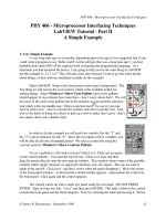
FIGURE 2.18
The SolidWorks window with all toolbars hidden using the F10 key
Workflow customization
When you first install and run the SolidWorks software, the SolidWorks Welcome screen shown in
Figure 2.19 offers you the option to customize the interface using one of three preset option pack-
ages. Special menu and toolbar settings are made for Consumer product design, Machine design,
or Mold design. After the software is initially installed, you only see this screen once, but you can
change all of the options in other places, including the Options tab of Tools ➪ Customize.
The three workflow customizations affect the interface as follows:
n
Consumer product design adds the Surfaces toolbar to the CommandManager.
n
Machine design adds Sheet Metal and Weldments toolbars to the CommandManager.
n
Mold design adds Surfaces and Mold Tools toolbars to the CommandManager.
Similar changes are made to the menus to hide or show menu selections as appropriate. You can
find more information about hiding and showing menu items later in this chapter.
If you want to select a different option after the initial setup, you can go to
Tools ➪ Customize ➪ Options, where you can specify a different choice. Figure 2.20 shows the
Options tab of the Customize dialog box.
47
Navigating the SolidWorks Interface
2
FIGURE 2.19
The Welcome to SolidWorks screen
FIGURE 2.20
The Options tab of the Customize dialog box, where you can select a different workflow customization
48
SolidWorks Basics
Part I
Menus
Everyone has his or her own style of working. For example, some people like to use menus and
others do not. Some like to use hotkeys and others like the mouse. An example of a tool that does
not have a toolbar equivalent is View ➪ Modify ➪ Section View, which is used to change the active
section view’s settings.
The most frequently used menu items are in the View, Insert, and Tools menus. All of the menus
shown in this section have all of the possible selections turned on. As a result, the View menu in
Figure 2.21 may contain options that are not available on your computer. Customizing menus is
covered later in this chapter. Figure 2.21 also shows the Insert and Tools menus, along with an
image of a menu with the Customize Menu mode activated.
The View menu is used primarily for turning on or off the visibility of entity types such as planes,
sketches, or temporary axes. You can also do this by using hotkeys or by putting extra items on the
View toolbar.
FIGURE 2.21
Popular menus
View Menu Insert Menu Tools Menu Customize Mode
49
Navigating the SolidWorks Interface
2
The Insert menu is used mostly for creating feature types for which you do not have a toolbar icon
on the screen. For example, although the Move Face tool is only on the Mold Tools toolbar, it has
many uses aside from mold design. You can find the Move Face tool at Insert ➪ Face.
The Tools menu is used primarily for sketch entities or tools for which you have no icon on the
screen. Several other commonly used tools, such as Measure, Equations, Customize, and Options,
are also available in this menu.
You can customize menus by adding or omitting items. By using the Customize Menu option at
the bottom of any menu—including shortcut (right mouse button) menus—you can remove items
from any menu by clearing the check boxes next to tools that you do not use. To bring back the
removed items, you can either go back to the Customize Menu or go to Tools ➪ Customize ➪
Options and click the Reset to Defaults buttons for menu and shortcut customization.
NOTE
NOTE
Be careful not to confuse this Customize Menu selection with the Customize…
menu selection on the Tools menu. Figure 2.21 shows the Tools menu being
customized.
The Tools ➪ Customize ➪ Options dialog box, shown in Figure 2.21, contains the Shortcut (right
mouse button) menu and Menu customization options. These options enable you to show all of
the menu items for both types of menus in a single stroke. By default, some items are hidden in
various menus. Keyboard customization is discussed later in this chapter. Keyboard shortcuts are
generally referred to as hotkeys.
NOTE
NOTE
SolidWorks terminology for Shortcut Menus, Alt-key (accelerator keys) shortcuts, the
Shortcut “S” bar, and Shortcuts/Keyboard customization is slightly confusing because
of these overlapping, yet unrelated, terms. For this reason, I will refer to Shortcut Menus as RMB
(right mouse button) menus from here on, because this is the standard terminology among
SolidWorks users. Shortcuts are also generally referred to as hotkeys among users. The Shortcut
Bar will be referred to as the “S” Toolbar, and the Alt shortcuts will be called Alt-keys.
Cursors
SolidWorks cursors are context-sensitive, and change their appearance and function depending
on the situation. Sketching cursors display a pencil and the type of sketch entity that you
are presently sketching. Sketch cursors also display some dimensional information about the
entity that you are sketching, such as its length or radius. Sketch cursor feedback is necessary for
fast and accurate sketching.
CROSS-REF
CROSS-REF
To learn more about sketch cursor feedback, see Chapter 3, Working with
Sketches.
The Select cursor changes, depending the item over which you move it. Cursor symbols also help
to remind you when selection filters are active. The cursor is frequently available as an OK button.
For example, after selecting edges for a Fillet feature, the RMB functions as an OK button. Figure
2.22 shows various cursors and their significance.
50
SolidWorks Basics
Part I
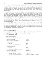
FIGURE 2.22
Various SolidWorks Cursors
Select
OK
selection
Select
sketch
plane
Sketch
line
FeatureManager and PropertyManager windows
The FeatureManager window is the panel to the left of the screen that shows an ordered list of features
describing how the part was built. SolidWorks users spend a fair amount of time using the
FeatureManager to edit or inspect models. Figure 2.23 shows the FeatureManager for a simple model.
FIGURE 2.23
The FeatureManager for a simple model
Splitter bar
Display pane icons
Display pane collapse arrows
FeatureManager filter
PropertyManager tab
FeatureManager collapse arrows
Rollback bar
Using the FeatureManager
There is a splitter bar at the top of the FeatureManager that enables you to split the
FeatureManager window into two windows, so that you can display the FeatureManager and
another window, such as the PropertyManager. Small arrows in the middle of the right separator
51
Navigating the SolidWorks Interface
2
can collapse the FeatureManager to increase screen space. (The F9 key also collapses or opens the
FeatureManager. Refer to Figure 2.23).
Display pane
You can open the Display pane flyout from the FeatureManager by using the double arrows at the
top-right corner. The Display pane helps you to visualize where appearances or hidden bodies
have been applied in a part document and additional functions in an assembly document. The dis-
play pane is helpful when looking for colors that are applied to the model at some level other than
the part level.
CROSS-REF
CROSS-REF
Appearances are covered in more detail in Chapter 5, Using Visualization
Techniques.
Rollback bar
The Rollback bar at the bottom of the FeatureManager enables you to see the part in various states
of history. Features can be added while the rollback bar is at any location. The model can also be
saved while rolled back.
FeatureManager Filter
One of the most useful elements of the FeatureManager is the FeatureManager Filter. The Filter
resides at the top of the FeatureManager. If you type text in the filter, SolidWorks will search fea-
ture names, descriptions, comments, tags, and dimension names for text matching the string, and
only show matching features in the window. This also works in assemblies, where you can filter for
part names or document properties. The filter is very useful for quickly finding parts, features,
mates, or anything else that shows up in the part or assembly FeatureManager. I think it is one of
the most useful enhancements in recent releases.
Using the PropertyManager
The PropertyManager is where you go to set most of the feature parameters, and where you edit
properties of selected items such as sketch elements. You can manually switch to the
PropertyManager using the tabs on the top of the Display panel, or allow it to pop up automatically
when your input is needed. The left-most tab in the row of icons is the FeatureManager tab, the
second from the left is the PropertyManager tab, the second from the right is the
ConfigurationManager tab, and the right most tab is the TolAnalyst. Other icons may also appear
in this area for drawings, or if you have add-ins such as PhotoWorks or SolidWorks Simulation
(formerly COSMOS) turned on. The ConfigurationManager tab appears with more detail in
Chapter 10, and the TolAnalyst tab appears again in Chapter 23.
One of the benefits of putting dialog boxes in the PropertyManager is that it saves a lot of space on
the screen. On the other hand, you will often need to make a selection from the FeatureManager at
the same time that the PropertyManager pops up and takes its place. This automatic pop-up
behavior is controlled by a setting in the Tools ➪ Options ➪ System Options ➪ General ➪ Auto-
show PropertyManager.
52
SolidWorks Basics
Part I
My favorite option for dealing with the PropertyManager is to detach it from the FeatureManager
so that you can see them side by side instead of one or the other. The detachable PropertyManager
is new in SolidWorks 2009. To detach it, drag the icon from the tabs out into the graphics area
and release. Once detached, the PropertyManager can be moved to a second monitor, floated
within the SolidWorks window, or docked. To put it back in its place under the FeatureManager,
just drag it back on top of the FeatureManager, allow it to snap into place, and release it.
If you do not like the detachable PropertyManager, you can use either the splitter bars to put the
FeatureManager on top and the PropertyManager beneath, or use the flyout FeatureManager.
When creating or editing a feature, you can access the flyout FeatureManager by double-clicking
the name of the feature at the top of the PropertyManager. The flyout FeatureManager is displayed
just to the right of the regular FeatureManager, in the main graphics window, and is transparent to
allow you to see the model through it. The various ways of combining the FeatureManager and
PropertyManager are shown in Figure 2.24.
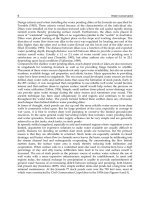
FIGURE 2.24
The detached PropertyManager, the flyout FeatureManager, and the split FeatureManager
Detached PropertyManager Flyout FeatureManager Split Feature
Manager
Task pane
By default, the Task pane sits to the right of the SolidWorks screen, although you can undock it
entirely. If you want to keep it open, click the pushpin in the upper-right corner of the pane. The
Task pane is shown in Figure 2.25.
53
Navigating the SolidWorks Interface
2
FIGURE 2.25
The Task pane
The Task pane is the home for several panels:
n
SolidWorks Resources. These are useful links for templates, tutorials, tech support,
news, GlobalSpec search, Tip-of-the-Day, and other resources.
n
Design Library. This includes locally stored libraries, Toolbox, and 3D Content Central.
This tab also contains “SolidWorks Content” which consists of additional library
resources that can be downloaded directly from the Task Pane.
n
File Explorer. This is a Windows Explorer–like interface that you can use to browse for
files.
n
SolidWorks Search. If you have installed the Windows Desktop Search with SolidWorks
2007 and indexed your files, you can perform searches that include filename and custom
properties.
54
SolidWorks Basics
Part I
n
View Palette. This palette allows you to visually select views and drag them onto a
drawing sheet.
n
RealView. This allows you to select appearances and scenes for your SolidWorks
documents.
n
Custom Properties. New functionality in 2009 enables you to create a custom interface
that goes inside this Task Pane tab that will help you enter custom property data quickly,
easily and accurately.
n
Recovered documents. After a crash, auto recovered documents are listed in this special
purpose Task Pane tab.
Status bar
The status bar is a non-intrusive way in which SolidWorks communicates information back to the
user. It is located at the bottom of the screen, and you can enable it from the View menu. Figure
2.26 shows the status bar in action.
FIGURE 2.26
The status bar showing a Tooltip for the Sketch Circle tool
The status bar can display the following information, indicators, and icons:
n
Progress as parts, assemblies, or drawings load
n
Tooltips for commands
n
Measurements
n
Sketch status for an active sketch
n
In-context editing
n
Suspend Automatic Rebuilds
n
Icons that allow you to turn Quick Tips off or on
n
Sheet scale for drawings
n
Cursor position for drawings and sketches
n
Whether you are editing the sheet, sheet format, or view of a drawing
Tags
Tags work like document properties, except that they do not need a property name; they just use a
value. A tag could be considered simply a keyword that you can associate with a part in an assembly
or even a feature in a part. Tags can be searched by SolidWorks Explorer or by the FeatureManager
Filter. You can assign tags by clicking the yellow tag icon on the status bar in the lower right-hand
corner of the SolidWorks window. Figure 2.27 shows a tag being added to a feature.
55
Navigating the SolidWorks Interface
2
FIGURE 2.27
Adding a tag to a feature
Quick Tips
Quick Tips appear in the pop-up window in the lower-right corner of the graphics window. They
can change as you work so that they are sensitive to the context in which you are working. They
are a great way for new users or infrequent users to learn or be reminded of the next steps available
to them. You can activate and deactivate Quick Tips using the question mark icon in the lower-
right corner of the SolidWorks window on the status bar. Figure 2.28 shows the Quick Tips
window in action.
FIGURE 2.28
Quick Tips in action
56
SolidWorks Basics
Part I
2D Command Line Emulator
This is a tool specifically for people who are coming to SolidWorks from AutoCAD. As the name
suggests, it adds a command line to the bottom of the SolidWorks window that works like the
AutoCAD command line in most respects. The available commands are somewhat limited com-
pared to those that are available in AutoCAD. This tool only functions in the 2D sketch mode, on a
drawing sheet, or in a drawing view; it does not work in a 3D sketch. The 2D Command Line
Emulator is shown in Figure 2.29.
FIGURE 2.29
The 2D Command Line Emulator in action
Available sketch tools in the 2D Command Line Emulator include Align, Arc, Array, ‘Cal, Chamfer,
Chprop, Circle, ‘Color, Copy, DDcolor, Dim, Dist, Ellipse, Erase, Exit, Extrude, Fillet, ‘Grid, Line,
List, Massprop, Mirror, Move, Offset, ‘Ortho, ‘Osnap, ‘Pan, Plot, Point, Polygon, Qsave, Rectangle,
‘Redraw, ‘Redrawall, Revolve, Rotate, Save, Saveas, ‘Snap, Spline, Trim, U (undo), ‘Units, ‘View,
and ‘Zoom. Commands that are preceded by an apostrophe (‘) can be used as transparent com-
mands, without exiting an active command. Notice that even the cursor changes to crosshairs.
BEST PRACTICE
BEST PRACTICE
The best way to learn a new software package is to embrace the new way, not to
cling to the old way. Although you may find the 2D Command Line Emulator more
comfortable to work with, you will not achieve the same results as you will with the SolidWorks
default sketching mode. For example, the resulting sketch entities created using the 2D
Command Line Emulator are not constrained in any way, and the endpoints do not even merge.
You can turn off the 2D Command Line Emulator by going to Tools
➪ Add-ins.
57
Navigating the SolidWorks Interface
2
Making the Interface Work for You
As engineers and designers, we all like to tinker with things to optimize efficiency and to apply our
personal stamp. When the SolidWorks software is installed, the interface is functional, but not
optimal. In recent new releases, the new features in SolidWorks tend to use the most radical
options available as the out-of-the-box defaults. In the previous pages, I have discussed managing
and customizing toolbars and menus. In the remainder of this chapter, I discuss more about cus-
tomizing the interface, and suggest some strategies that you might use to help customize your
work environment.
Customizing colors
You need to be aware of a few things before you change all of the standard colors in the
SolidWorks interface to whatever strikes your fancy. The first is that SolidWorks does not auto-
matically alter text color to contrast with your background. As a result, if you set the background
to black, and the text is black, you won’t be able to see the text. This may seem obvious to some
people, but AutoCAD automatically changes text color to contrast with the viewport background,
and so AutoCAD users may take this functionality for granted.
Default selection colors
Between the 2007 and 2008 releases, SolidWorks changed some of the default colors used in the
interface. However, not all users will see these changes immediately. Since the software was ini-
tially released in 1995, the color for selected items has been green. Users have based their color
selections for part colors on this default, generally avoiding the green color so selections could be
seen more easily.
Starting with the 2008 release, the selection color is now blue. But this is only the case if you have
a new computer without a prior installation of SolidWorks on it. If your computer already has an
earlier version of SolidWorks, you will continue with the green selection color even in 2008, but if
you put 2008 or later on a computer that never had a version of SolidWorks, you will get the blue
selection color.
Does it really matter whether the selection color is green or blue? No. What does matter is interface
predictability and consistency. The color default selection color changing from one to another
without any pressing need qualifies as random change, and I don’t believe it positively impacts
software usability. If the color change has a negative effect on your use of the software, be aware
that you can change it back if you like. How to make the changes is described in this section.
58
SolidWorks Basics
Part I
With the introduction of RealView, the selection appears to glow in addition to changing colors.
RealView is hardware driven visualization technology in SolidWorks that has grown in scope over
the course of a couple of releases. RealView is described in more detail in Chapter 5, Using
Visualization Techniques.
All of the interface colors are controlled at Tools ➪ Options ➪ Colors. The selection color in partic-
ular is set at Selected Item 1, as shown in Figure 2.30.
FIGURE 2.30
Changing interface colors
Notice that you can set a color scheme. I recommend that if you want to change the colors used in
the interface, you save the settings as a color scheme so that the scheme can be re-created easily
later or handed off to another computer. Color schemes are stored in the Windows registry, not as
separate files. To transfer color settings to another computer, you will need to either use the Copy
Settings Wizard or manually copy data from the Windows registry.
Before making changes, you might consider saving your initial settings as a separate scheme so you
can get back to them if you need to.
CAUTION
CAUTION
Making changes to the Windows registry can adversely affect software installation
and hardware performance. You should not attempt changes to the registry unless
you know exactly what you are doing.
59
Navigating the SolidWorks Interface
2
Background options
Some colors should be avoided for the background, or you should at least make some other
changes if you choose these colors. Black is used with fully defined sketches, dimensions,
FeatureManager text, and annotations. Blue backgrounds can mask the underdefined sketch color.
Bright green backgrounds can cause problems with seeing selected items. Bright red, aside from
being a terrible color to stare at all day, also does not contrast well with some of the red highlights
and error colors.
You might say that whatever color background you select, it makes items or features difficult to
see. For this reason, many users choose a gradient background, which allows you to pick colors
where items are always visible on one half of the screen or the other. Staring at a white screen all
day can be uncomfortable for your eyes, so pick colors that allow you to see everything with “rea-
sonable” contrast, yet are not glaringly bright. Very high contrast is hard on the eyes, and low con-
trast may make it difficult to distinguish items on the screen.
You have to consider what the purpose of the background is. Some people doing presentations
may want the background to be attractive while otherwise staying out of the way. Others may only
need the background to contrast with whatever is in front of it in a way that does not strain your
eyes. For writing a book, the background generally needs to be white to match the page. No one
scheme will suit all needs.
In addition to colors and gradients, you can use an image as the graphics window background.
This gives you a wider range of customization capabilities, and several sample images are already
available in the default settings.
RealView also adds some capabilities with scenes. Scenes can be applied from the RealView tab on
the Task Pane. RealView offers three different types of scenes: Basic, Studio, and Presentation. Of
these, I find the Studio scenes to be the best when I need something of that sort. RealView, along
with scenes, is described in more detail in Chapter 5.
Customization strategies
You can easily customize many aspects of the SolidWorks interface, including:
n
Toolbars
n
Menus
n
Background colors or images
n
PropertyManager skins
n
Task pane location
n
Hotkeys
n
Macros
n
Custom application programming
60
SolidWorks Basics
Part I
Whether or not you should customize each of the previous items depends partially on how much
time and energy you have to spend, as well as how much money you are ready to dedicate in the
case of custom programming.
Hotkey approaches
Some of us old-timers prefer to use the keyboard over the mouse. If your hand-eye coordination is
as bad as mine, you may also choose this approach. I can type without looking at the keyboard,
but when I use the mouse, it takes me a few seconds to aim at an icon and hit it accurately. This
means that I customize SolidWorks to use as many hotkeys as possible, and remove icons from the
interface if I have them on a hotkey. Unfortunately, my memory is as bad as my eyesight, and so
remembering 75 hotkey commands is a bit of a problem. I admit to having a printed list of hotkeys
taped to the side of my monitor. While I know that needing to read the list to find a particular hot-
key defeats most of the purpose of using them in the first place, I just accept it as a learning aid.
This is a self-solving problem, because the hotkeys that I use the most are the ones that I learn
most quickly.
I generally do not advocate trying to standardize a hotkey scheme across multiple users, unless the
users all agree to it. The underlying reason for writing a section entitled “Hotkey approaches” is
that everyone remembers things differently in the first place.
Any command that I use more than a few times an hour is worth assigning to a hotkey. I like to
use alliteration when assigning keys to help with my faulty memory. Most-frequently used com-
mands are assigned single-letter hotkeys, and less-frequently used commands are assigned combi-
nations. Thus, Tools Options is linked to O, Measure to M, Select Vertex to Shift+V, and Curve
Projected to Ctrl+J (Ctrl+P is the Windows standard for the Print command). Other people like to
group keys into easy-to-reach combinations, and so the Q, W, A, S, Z, and X keys are often
assigned first for right-handed mouse users.
Organizing hotkeys
Hotkeys are assigned and organized in the Tools ➪ Customize ➪ Keyboard dialog box, as shown in
Figure 2.31. This interface enables you to see all of the hotkeys (called shortcuts in the list) easily. If
you try to enter an existing hotkey, SolidWorks issues a prompt, telling you that the key is
assigned to another command and what the command is, and asking you if you want to clear the
other instance of the hotkey and make the new one active. You can also print out or copy to the
Clipboard a list of only commands that use hotkeys.
Because the list of commands is so long, a Search function is available, and a drop-down arrow
makes only the commands from a selected menu visible. The list of commands is organized by
menu name, and the menus are listed as they occur in the interface. Fortunately, here on the
Keyboard tab, SolidWorks allows you to sort using the column headers to list the menus, com-
mands, or hotkeys in alphabetical order, simply by clicking the column header. This is a highly
usable interface, one of my favorite interface changes in the last several releases.
61
Navigating the SolidWorks Interface
2
FIGURE 2.31
Tools
➪ Customize ➪ Keyboard — the hotkey interface
Using the keyboard
Moving between the mouse and the keyboard can be bothersome and time-consuming. In addition
to the hotkey approach, you can use another keyboard method to save time. Many users become
adept at using the Alt-key combinations to invoke menu items. Most menu items in Windows
applications contain a single underlined letter.
To access a top-level menu, you can hold down the Alt key and press the underlined letter for that
menu, and then just press an underlined letter in the menu to access specific commands. This
technique enables you to navigate most of the interface without using the mouse. For example, to
exit SolidWorks, instead of using the mouse to click the red X in the upper-right corner, you could
press Alt+F, X. In Figure 2.32, you can see that the F in File is underlined, as is the X in Exit.
NOTE
NOTE
The SolidWorks documentation terminology becomes further confusing when talk-
ing about Alt-keys (accelerator keys). It says that the general class of keys is called
shortcuts, which can be either accelerator keys or keyboard shortcuts. How these are distin-
guished from shortcut menus and shortcut toolbars is not clear. Again, for the purposes in this
book, I refer to the shortcut menus as RMB (right mouse button) menus, accelerator keys as Alt-
keys, and keyboard shortcuts as hotkeys, which is more in line with standard usage than the doc-
umented terminology.
62
SolidWorks Basics
Part I
FIGURE 2.32
Accelerator Keys in the File menu
You may potentially run into conflicts when using Alt-keys. A combination of Alt + another key-
board key is a valid use of a hotkey combination. If you use any Alt hotkey combinations, it is
likely that you have seen a conflict like this. In cases of conflict, the hotkey combination seems to
gain priority over the Alt-key accelerator.
Fewest number of icons
In order to maximize valuable space on the monitor, many SolidWorks users strive to minimize
the number of toolbar icons on the screen, or confine it to two rows of toolbars. You can do this by
using the CommandManager, flyout toolbars, the “S” toolbar, right click toolbars, and hotkeys, and
removing unused icons, as well as the other techniques discussed here.
Having an uncluttered workspace is definitely a plus, but having easy access to commands is the real
purpose of an interface in the first place. You need to strike a balance between too much and not
enough. The more kinds of work you do in SolidWorks, the more tools you will need to have avail-
able. If you only create relatively simple machined parts and drawings, you will need fewer tools
available than someone who does complex plastic part assemblies with rendering and animation.
Device approaches
If you have never used a Spaceball or equivalent view-manipulation device, you should consider it.
They are wonderful devices and do far more than just spin the view. Most of the devices also have
63
Navigating the SolidWorks Interface
2
several programmable buttons that you can link to menu items. They can move drawing views,
parts within assemblies, and even manipulate selected objects in other Office applications and Web
browsers.
Portions of the 2009 edition of this book have been written on a Tablet PC. A tablet might not be
ideal for long periods of SolidWorks usage, but I use it regularly for presentations and even model-
ing when I really want to get the feel of drawing a line by hand, The stylus is not quite as intuitive
as a pencil, but it is less of an impediment to the tactile feel of actual drawings than a clunky
mouse.
Macros
Macros are short snippets of programming code that have a particular function. Most macros are
small and intended for simple tasks that are repeated many times, such as changing selected
dimensions to four decimal places or zooming the screen so that it is sized 1:1 (actual size). Macros
may be recorded, written from scratch, or a combination where you record a particular action to
be used as a starting point and then embellish it manually from there. Recorded macros may not
always record the parts of the action that you want to make into a macro, but you can edit them
manually to include anything that you can program with VISTA (Visual Studio Tools for
Applications), which is included with the base SolidWorks package at no extra cost.
To access macros by using hotkeys, follow these steps:
1. Make a folder in your SolidWorks installation directory called “macros.”
2. Copy macros into this folder.
3. Start (or restart) SolidWorks.
4. Go to Tools ➪ Customize ➪ Keyboard.
5. Scroll to the bottom of the list under the Macros category, and assign hotkeys as
you would for standard SolidWorks commands.
Whether you are skilled at writing or recording macros, or you are just using macros collected
from other people, they can be huge time-savers and offer functionality that you would not other-
wise be able to access. Many of my accumulated macros have been made obsolete by that function-
ality being incorporated directly into SolidWorks.
Saving custom interface settings
Once you have set up your menus and toolbars, worked out all of the custom colors, figured out
your hotkey usage, and connected your macros, you don’t want to lose these settings when you
reinstall the software or move to a different computer. Another user may want to share your set-
tings, or you may want to transfer them to your home computer (for modeling the new deck or the
doghouse, of course). Fortunately, these settings are very portable.
You can use the Copy Settings Wizard to save these settings out to a file. Access the wizard
through Start ➪ Programs ➪ SolidWorks 2009 ➪ SolidWorks Tools ➪ Copy Settings Wizard. This
creates a file with an *.sldreg file extension. You can restore settings by double-clicking this file on
a computer that has SolidWorks installed on it.
64
SolidWorks Basics
Part I
NOTE
NOTE
You may need to have administrator access to your computer to apply a SolidWorks
registry file.
The SolidWorks settings are actually Windows registry settings. The file that is saved by the wizard
is just a registry file that has a different extension to prevent it from being applied too easily.
Saved-out Windows registry files have a *.reg file extension, and are integrated into the registry by
simply double-clicking them. If you are not familiar with the Windows registry, you should not
make direct changes, because even small changes can cause serious problems with your operating
system, installed software, or even hardware. The settings that are saved out by the Copy Settings
Wizard are safe to transfer between computers. In order for the Copy Settings Wizard to work, you
need to have Administrator-level access to your computer. The Copy Settings Wizard is shown in
Figure 2.33.
FIGURE 2.33
The Copy Settings Wizard
Working with multiple document windows
In SolidWorks, as in other areas of life, things can become chaotic. You may sometimes have the
luxury of working on a single part at a time, but more often, you will find yourself with several
documents open at once. This is a common situation for most users. Fortunately, SolidWorks has
several methods for dealing with “information overload,” to help you sort through it all.
Window management
Like most other Windows applications, SolidWorks can arrange the open document windows in
one of several ways that are available through the Window menu (see Figure 2.34):
n
Cascade. Most useful for accessing documents that are to be edited one by one.
65
Navigating the SolidWorks Interface
2
n
Tile Horizontally. Most useful for wide and short parts.
n
Tile Vertically. Most useful for tall, narrow parts, or documents where you want to
compare items in the FeatureManager.
n
Arrange Icons. When windows are minimized to icons, this menu selection arranges the
icons neatly, starting in the lower-left corner of the window.
FIGURE 2.34
The Window menu
The images in Figure 2.35 are meant to show the arrangement of the windows, not the content of
the windows. Also remember that you can use the F9 key to close the FeatureManager, the F10
key to remove the toolbars to create extra interface space when arranging several windows in the
graphics window and the F11 key to remove portions of the interface and allow you to work full
screen.
Changing windows
You can use several techniques to change from one window to another. By clicking on the Window
menu, you can view a list of open document windows (refer to Figure 2.34). You can then select
the desired window directly from this menu. If more than a few windows are open, a More
Windows option appears at the end of the list, as shown in Figure 2.36. Clicking on this option
brings up a separate window that enables you to select from the complete list.
When a smaller number of windows are open, a simpler way to change windows is to press
Ctrl+Tab. This is a Windows standard technique that also works in other Office applications.
Ctrl+Tab takes you in one direction in the list of open windows, and Ctrl+Shift+Tab takes you in
the opposite direction through the list. Starting with the 2008 release, Ctrl+Tab brings up the
Open Documents interface (see Figure 2.36). This enables you to visually select the document that
you want to open.
Additionally, the R hotkey by default opens the Recent Documents dialog, similar to the Recent
Documents list in the File menu. This can also be accessed via the File menu if necessary. The
Recent Documents dialog is shown in Figure 2.37.
66
SolidWorks Basics
Part I
FIGURE 2.35
Window Arrangements: Cascade, Tile Horizontally, and Tile Vertically
67
Navigating the SolidWorks Interface
2
FIGURE 2.36
The Open Documents dialog
FIGURE 2.37
The Recent Documents dialog
Tutorial: Getting to Know the Interface
By this point, you really have not learned much about making parts, assemblies, and drawings in
SolidWorks, but you have learned quite a bit about using the interface. In this tutorial, you get
some hands-on practice at manipulating the interface. This tutorial is intended to reinforce the fol-
lowing skills:
n
Adding and removing toolbars
n
Adding and removing toolbar buttons
n
Adding and removing items from drop-down and RMB menus
68
SolidWorks Basics
Part I
n
Setting up the CommandManager
n
Setting up hotkeys
n
Linking a hotkey to a macro
n
Changing interface colors
Copy the existing settings
Regardless of what your initial settings are, you do not want to lose them. Before you start to make
changes to your system, you should save out the existing settings to a file from which they can be
recovered. You can do this using the Copy Settings Wizard, as shown in Figure 2.38.
FIGURE 2.38
The Copy Settings Wizard
To use the Copy Settings Wizard, follow these steps:
1. Close SolidWorks.
2. Click Start ➪ Programs ➪ SolidWorks 2009 ➪ SolidWorks 2009 Tools ➪ Copy
Settings Wizard.
3. Select Save Settings, and click Next.
4. Enter a location and a name for the file.
5. Select the items that you would like to save. For the purposes of this tutorial, make
sure that the following options are selected: Keyboard Shortcuts, Menu Customization,
Toolbar Layout, and All Toolbars.
6. Click Finish. Browse to the location where you saved the file and make sure that it is
there.
69
Navigating the SolidWorks Interface
2
Set all interface items to their default settings
You can set the interface back to the default settings using one of two methods. The first method,
editing the Windows registry, may not be available to all users. It requires Administrator access to
your computer and a good familiarity with Windows.
CAUTION
CAUTION
Editing the Windows registry can be dangerous if you make a mistake. Do not
attempt this method is you have any doubts about what you are doing.
To set SolidWorks back to its default settings, follow these steps:
1. Close SolidWorks.
2. Click Start ➪ Run.
3. Type regedit, and click OK.
4. Browse to HKEY_CURRENT_USER\Software\SolidWorks\SolidWorks 2009 or
the appropriate folder for the version that you are using.
5. To return all settings in SolidWorks back to default, rename the entire SolidWorks
2009 folder to include “(old)” at the end of the filename.
6. Close the Registry Editor.
7. The folder is re-created when SolidWorks starts up again, and is populated with
default values. If you need to get the previous folder back, you can delete the new one
and rename the old one to remove the “ (old)” from the name.
The second method, which is less risky but less complete, is to go to the main locations and use
the tools provided to return settings to their defaults. Restart SolidWorks and create a new blank
document (you cannot display the Customize dialog box without a document open). To access the
resets for the interface, do the following:
1. Click Tools ➪ Options ➪ General ➪ Reset, and go to the bottom-left area of the dia-
log box.
2. Click Tools ➪ Customize ➪ Toolbars ➪ Reset, and go to the bottom-left area of the
dialog box.
3. Click Tools ➪ Customize ➪ Menus ➪ Reset All, and go to the right side of the dialog box.
4. Click Tools ➪ Customize ➪ Keyboard ➪ Reset to Defaults, and go to the upper-right
area of the dialog box.
5. Click Tools ➪ Customize ➪ Options; there are three Reset to Defaults buttons along
the left side of the dialog box.
Customizing the CommandManager
Now that you have restored the default settings, you can begin customizing the interface with the
CommandManager. To do this, open a part document or create a new one, then RMB click anywhere
on the CommandManager, and deselect the Use Large Buttons with Text option, as shown in Figure
2.39. When you have done this, the check mark should no longer appear in front of the option.