Mobile Robots book 2011 Part 5 docx
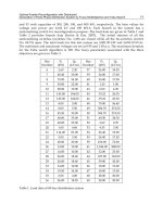
Bạn đang xem bản rút gọn của tài liệu. Xem và tải ngay bản đầy đủ của tài liệu tại đây (1.4 MB, 25 trang )
Bionic Limb Mechanism and Multi-Sensing Control for Cockroach Robots 91
then the speed of image processing can be enhanced greatly. For a complex system that
contains multi-sensor information, owing to modeling error, external disturbance, load
fluctuation and temporary set causing position error, state space variables are inter-coupled.
Consequently it is very challenging to design realizable filter and controller in system state
space. Effective methods have to be devised to realize multi-sensor information processing,
hence intelligent motion control.
Although a cockroach has agile movement, its nervous system is very simple (Beer et al,
1997). The limited capacity of the simple neural network shows that the nerve centre does
not take care of everything itself, and that each leg's movement is self-controlled by each
leg's controller. It is therefore suggested that cockroach robot control system should adopt
principal and subordinate distributed control structure (Espenschied, 1996). Master
controller of brain level allocates task for each master controller of leg level based on
programming task requirement. Master controller of leg level sends commands to its
subordinate controllers which are the individual joint controllers. There are information
interaction between principal and subordinate controllers to realize intelligent motion
control. Control algorithms should be simplified to accelerate controller's operational speed.
Cockroach robot has more than 10 years research history, but it is still in its infancy. In the
ongoing project, the concept of region control has been proposed. It is designed to substitute
routine point control scheme. Region control has many examples in life, such as chess player
placing chessman. Players do not need to place chessman in the decussate point exactly, but
a region near the ideal point. It is obvious that the point is the limit of region and reducing
the region leads to the point. Intuitively it can be concluded from the problem of placing
chessman that region control is easier than point control and requires much less
computational time. The velocity of body's movement using region control can be faster.
Ascertaining the size of the region of interest based on task requirements helps a cockroach
robot achieve movement rapidity and flexibility.
3. Design of Bionic Limb for Smooth Motion
3.1 Multi-Discipline Fusion Approach
In the multi-discipline fusion approach, bionics, mechanism and disperse adaptive control
theory are combined to realize harmonious development of bionic mechanism and modern
control theory. Preliminary research indicates that dynamics characteristic of organism
incarnates bionic dispersed intelligence. Disperse adaptive control theory and technology,
which studies bionic mechanisms, extends biologic dispersed intelligence to artificial
intelligence. Multi-discipline fusion approach offsets single subject’s difficulty caused by
limitation of technology. Combining cockroach robot’s leg configuration and calculation
function draws the knowledge from math, mechanics, mechanism, artificial intelligence,
electronics and control theory.
Bionic cockroach robot can be viewed as an integrated sensing, opto-electro-mechanical
(OEM) system with real time adaptive control. Such an OEM system should have small
volume, high precision and good real-time performance. Commercial sensors like
mechanical sensors and light frequency and phase modulation sensors cannot be easily
deployed in bionic limb design due to the volume factor. Electric and magnetic sensors are
small and sensitive, but have limitations in reliability and anti-interference
electromagnetism stability. Especially for a cockroach robot, its figure should be gracile, and
Mobile Robots - State of the Art in Land, Sea, Air, and Collaborative Missions92
be easily integrated in arrays. Such a robot should have good dynamic response, high
sensitivity and strong anti-interference electromagnetism ability. Based on synthesizing all
factors, differential light intensity modulation fibre optic sensor becomes a preferred sensor
of the cockroach robot sensor system.
3.2 Biomimetics Approach
Bionic cockroach robot can be considered as a parallel mobile robot with six legs.
Development of such a robotic system needs to cover robot’s configuration design to
achieve dexterous movement; and modelling and dynamics control of a cockroach robot
with optimal configuration. This work aims to analyze existing techniques in design of
parallel kinematic machines, and conduct fundamental research and innovative mechanism
design to achieve motion smoothness in cockroach robots.
In consideration of joint drives of hip, knee and ankle moving in partial coupling,
configuration design, dexterous workspace, and design fundamental of optimal coupling
are to be ascertained. In terms of modelling, kinematics and dynamics control, high
redundant arithmetic control and analysis of singularity workspace and control arithmetic
of avoiding singularity need to be studied.
In developing a bionic mechanism, optimum coupling design hip, knee and ankle joints,
corresponding to the model of system and analysis of movement, is necessary. The core of
this problem is to discover the secret of cockroach’s movement mobility based on
mechanism theory, to study high redundant control arithmetic and mechanism design when
being overdriven, and to supply hardware base for the realization of bionic cockroach robot.
In terms of leg mechanism design, two approaches are considered; i) bionics approach, and
ii) abstract transplant approach. The base of bionic cockroach robot’s mechanism design of
hip, knee and ankle comes from illumination of research on hip, knee and ankle joints of
cockroach. There are two bionic methods: one is mechanism biomimeticsወthe other is
function biomimetics. Function biomimetics is combined with mechanism biomimetics for
the design of cockroach robot’s leg configuration. Not only does such a combinatorial
design method assimilate the merit that biologic cockroach’s limb mechanism possesses
movement agility and smoothness, but also overcomes the difficulty that complete imitation
of cockroach’s structure and functions is impossible because of technological limits.
The abstract transplant approach is to emulate cockroach limb being elastic. It is impossible
for a stiff pole to realize limb mobility. While it is difficult to find an elastic material having
similar properties to cockroach’s limb, limb's local function can be simulated with a spring
mechanism which would greatly simplify the leg mechanism design.
Before the detailed design, theoretical analysis of leg mechanism of cockroach robot,
kinematics and dynamics modelling are carried out. It is followed by simulation and
experimental verification. Verifying the correctness of the theoretical model via simulation
can economize time and cost, and is simple and effective. Further experimental studies and
prototyping are conducted to validate rationality and correctness of correlative theory and
arithmetic, improve the design and reliability, and provide the feedback to refine the theory.
Bionic Limb Mechanism and Multi-Sensing Control for Cockroach Robots 93
3.3 Design of Bionic Joints
3.3.1 Design of Bionic Hips and Knees
Based on physiological characteristics of cockroach’s front, middle and hind legs, the motion
feature of each leg is observed. Front leg is deft and mainly used to turn and adjust body
pose. Middle leg is swift and mainly serves to hold and turn body. Hind leg is strong and
powerful, and drives a cockroach to walk. The mechanisms of front, middle and hind legs
are designed differently to suit the motion characteristics. Fig. 7 illustrates front, middle,
hind legs structure.
Knee joint
Moving platform
Fixed platform
Fixed knighthead
Feed screw
Hip joint
Knee joint
Hip joint
Hip joint
Knee joint
Front leg Middle leg Hind leg
Fig. 7. Structure sketch of cockroach robot’s leg
In the front leg, hip joint is designed to be 3-DOF globe joint, and knee joint to be 1-DOF
rotary joint. In the middle leg, hip joint is a 2-DOF rotary joint, and knee joint 1-DOF rotary
joint. As for the hind leg, hip and knee joint are all designed to be a 1-DOF rotary joint.
Ankle joints of all legs are fixed structure. Altogether 18 degrees of freedom are required to
realizing cockroach robot’s agility function completely. The 3-DOF in the front leg hip joint
is important for cockroach robot mobility and terrain adaptation. In this project, the concept
of parallel kinematic globe joint is proposed to realise the front leg hip joint.
The concept of globe joint emulates biomimetics exhibited by biological systems. Human
hip and shoulder joints are globe joints. They contain all rotational DOF of Euclidean space,
and therefore have outstanding movement rapidity and mobility. A common approach in
designing bionic leg is that the robot globe joint is approximated by two 2-DOF joints that
have two orthogonal axes and the link is constructed as a 1-DOF rotary joint. This work
proposes a scheme that realizes globe joint function by three parallel telescopic mechanisms.
The drive for the telescopic mechanism may adopt one of three feasible methods, namely,
air cylinder, pneumatic artificial muscle and feed screw. In this work, feed screw driven by
motor is chosen for its simple motion control.
Mobile Robots - State of the Art in Land, Sea, Air, and Collaborative Missions94
Fig. 8. Sketch of globe joint
3.3.2 Design of Bionic Flexible Joints
Most biological organisms are flexible. It is one of the main reasons why an organism can
easily complete all kinds of difficult movements. Such a built-in flexibility in robot joints
would allow a robot to move reposefully. For the bionic cockroach robot under
development, flexibility is in-built at globe joint and rotary joint. Front leg flexible globe
joint, shown in Fig. 8, comprises a moving platform, a fixed platform and four knightheads
that connect the two platforms. Moving and fixed platforms are two disks with different
diameters. The centres of moving and fixed platforms are connected by an invariable
knighthead while the other three knightheads are connected by telescopic feed screws.
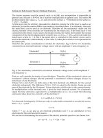
Fig. 9 illustrates the single feed screw connection of globe joint. A flexible element is
installed between feed screw nut and joint matrix, which makes front leg of cockroach
flexible. The parallel link is coupled to the fixed and moving platform through universal
joints. Fixed coordinate is placed in triangular centre of lower platform.
Motor
Universal
joint
Flexible
element
Feed
screw
Rigid pole
Universal
joint
Fig. 9. Design of bionic cockroach robot’s flexible joint
The model of universal joint is shown in Fig. 10. The two axes of rotation in the universal
joint are two orthogonal axes of the plane that the fixed or moving platform belongs to. The
outer ring turns relative to the ground along axis 1, while the inner ring turns relative to
outer ring along axis 2. Proper setting of flexible element can be used to fix the other
rotational DOF. Elastic material can be used to design the foot, and this will make the bionic
robot more adaptable to terrains.
Bionic Limb Mechanism and Multi-Sensing Control for Cockroach Robots 95
Inner ring
Outer ring
Inner ring
Outer ring
Fig. 10. Globe joint feed screw connection
3.4 Parallel Driver Structure
A driver structure would affect each leg and unitary movement performance of cockroach
robot if the coupling between hip and knee joints is weak. Before the design of mechanism,
modelling and movement analysis of the bionic system are carried out.
Different mechanism coupling modes are studied by using graph theory.
Change of configuration is analyzed to seek best description method of coupling mechanism,
and studied with structurology, kinematics and dynamics.
Universal kinematics and dynamics models containing geometry and movement restriction
are established.
The effect of singularity configuration on coupling mechanism form is analysed.
Self-motion manifold under high redundancy condition, and mission-oriented optimal
control are formulated.
The dynamical equation for single body is established using the Newton-Euler method.
Then multi-body dynamical equation is then established. Constraint counterforce can be
eliminated by substitution.
At the initial stage of designing biorobot, 3D robot modelling, dynamic performance and
control simulation are integrated using virtual prototyping technology. Firstly, apply
modern design theories to biorobot domain and establish 3D dynamic simulation.
Secondly, establish a model to finalise biorobot performance analysis and obtain test data in
order to improve biorobot system design performance, economize physical prototype,
finalise the design and simulation platform for the design and theoretical analysis of
biorobot.
Thirdly, establish mechanical model and dynamical model of the biorobot using virtual
prototyping technology. Biorobot overall performance is forecasted, and the feasibility of
trajectory is verified. Movement simulation and statics, kinematics and dynamics analysis
are carried out to achieve necessary displacement, velocity, acceleration, force and moment
curve. As such, optimal joint configuration is obtained, and physical design of the prototype
is optimised to improve the overall performance of the biorobot.
Mobile Robots - State of the Art in Land, Sea, Air, and Collaborative Missions96
4. Multi-Sensing in Bionic Cockroach Robot
A cockroach has an exceptional ability to navigate freely in all-weather conditions. In
addition to its visual navigation, it has a powerful detection system built into its legs and
feelers to detect its contact states with the environment. These sensing and navigation
abilities are important for biologically inspired robot which needs to execute demanding
tasks in difficult situations, such as search and rescue, homeland security, logistics in natural
disaster, etc.
Multi-sensor information fusion technology is the key to realize intelligent motion control of
cockroach robot. To ensure the fidelity of time-dependent sensor information, the
information processing has to be carried out in real time. In face of a large amount of
information including visual images, the real-time processing becomes very difficult.
Cockroach has visual, tactile, taste, smell sense function, etc. For practicality, only visual and
tactile sensors are considered at this stage. The vision system mainly utilizes infrared
imaging sensors, and the tactile sensing system is built upon optical fibre sensors.
4.1 Development of All-Weather Visual Navigation Systems
4.1.1 Imaging Device
Infrared imaging technology has been widely used for sensing natural environment where a
robot operates. For a bionic cockroach robot to emulate its biological counterparts, its visual
sensing system must satisfy two requirements, i) real-time binocular stereo image
acquisition, and ii) real-time high precision 3D imaging processing and recognition. These
would equip the robot with all-weather situational awareness and judgment ability.
Non-scan infrared imaging system and multivariate array infrared detector are able to
provide real-time environment image. The fundamental is that infrared radiation power is
converted to electrical signal detected by the detector. After being amplified, the signal is
converted to a video standard signal. One disadvantage of commonly available infrared
imaging devices is that they are large and cumbersome. There is a need to improve on the
size of optical lens, develop integrated optics, and subsequently miniaturise the entire
imaging system.
4.1.2 Calibration
The calibration process aims to establish the relationship between two views in order to
extract 3D visual information about the operating environment. Imaging aberrance
presented in real life and caused by lens affects the accuracy of image processing results.
Matching of two correlation images in the binocular visual device, and abstraction of image
characteristic points require data fusion. The calibration process associates images captured
by two video cameras that are unattached, and to abstract common information for
restoring the fidelity of imaging information.
4.1.3 Recognition
Identification of image feature points and reconstruction of three-dimensional entity data
are the key to the visual navigation ability of a cockroach robot. Changing of actual imaging
circumstance will lead to the different imaging effect and excursion of characteristic points
Bionic Limb Mechanism and Multi-Sensing Control for Cockroach Robots 97
in binocular imaging. This would cause the probability problem in truthful identification of
image features.
So far there has been no practical system that could recognise natural features in all-weather
conditions reliably. Therefore, it is necessary to develop a robust and novel detection
algorithm that combines high processing speed and efficiency. Wavelet algorithm can be
applied for navigation of mobile robots.
The image recognition involves image segmentation, identification and movement judgment.
Optimal internal and external imaging parameters can be solved using Tsai imaging model.
At the same time, binocular image matching handles standard imaging template and
imaging characteristic points. Then correlation pre-processing of images is carried out to
reduce image noise and enhance background contrast.
In the abstraction and identification of image characteristic points, the image processing
system adopts the wavelet arithmetic to identify contour objects of obtained visual image. It
also recovers object shapes and obtains the 3D shape outline of the object by utilizing
binocular visual demarcation and data fusion. It further modifies the current 3D model and
obtains the position error and external position error of the object by comparing the
preliminary 3D model with the current 3D model obtained from video images. Filtering out
the false characteristic points, true characteristic points based on current 3D model can be
obtained.
4.2 Development of Novel Tactile System
Cockroach’s powerful sensing abilities are further enhanced through its tactile perception
(leg pressure sensing) of the environment. Indirectly a cockroach senses the leg velocity,
high-frequency vibration, surrounding wind velocity, contact softness, ground condition,
obstacles, etc. At present there is not much research work that studies the function of fuzz in
cockroach’s limb. To emulate some of the tactile abilities of a biological system, a highly
integrated tactile system with good stability and high precision need to be developed to
satisfy the navigations needs of cockroach robot.
4.2.1 Fibre Optic Sensing for Cockroach Robot Tentacles
Fibre optic sensors are identified as a potentially suitable candidate to emulate the sensing
functions of cockroach leg feathers and head tentacles. Light intensity modulated fibre optic
sensor has small volume, high precision and real-time characteristics. Considering the fine
structure of cockroach leg feathers, supersensitive light intensity modulated fibre optic
sensors are deployed. The sensing system collects real-time data of pressure, vibration,
direction of wind and contact softness, which are produced by the robot’s leg movement
and its contact with the environment. Composite signal is obtained using optical fibre array.
Through multi-path signal processing based on difference measurement step by step,
environmental information can be extracted and situational awareness can be achieved.
To mimick the function of cockroach head tentacles, high strength optical fibre is adopted.
Changes of light intensity caused by the change of external pressure, wind direction and
vibration are thus detected in real time. These physical changes are converted to electronic
signals which can be processed internally using photoelectricity transition array. Besides
tactile sensor, head tentacles incorporates non-contact near-infrared ranging sensor to
enhance the robustness of locating objects and detecting obstacles in a poor visual
Mobile Robots - State of the Art in Land, Sea, Air, and Collaborative Missions98
environment. This sensing approach adopts a specific type of bismuthate optic fibre which
is controllable and has near infrared high degree of transparency to guide and focalize light.
Thereby suitable ranging position can be selected by changing the position of the head of
optic fibre. For illuminant and photosignal transition devices, integrated near infrared
semiconductor illuminant, which has a high contrast from background environment light,
and photoelectric conversion semiconductor array are chosen respectively.
4.2.2 Cockroach Robot’s Tactile System - Leg Feathers and Head Palp
Inspired from tentacles of rodents, a tentacle sensor based on the Position Sensitive Detector
(PSD) and Laser Diode (LD) has been designed. The sensor uses PSD as the sensing element;
and LD as the incidence light source. The sensor has certain advantages including compact
structure; light weight; and ease of processing, assembling, and debugging.
The 2D PSD element, measured 3 mm × 3 mm, can detect the rotation displacement and
direction of tentacle simultaneously. To be able to detect texture and roughness of an object
in contact, the tentacle of the sensor is designed to be thin poles made of flexible material of
9 ~ 15 cm in length. A light-shading film is fixed near the root of the tentacle, about 2 ~ 3
mm away from the root, In addition, a small hole with a diameter of 0.8 ~ 1.2 mm is opened
from the film to receive the light from LD. Through this mechanical design, the tentacle
automatically returns to its initial position if it is not in contact with the object to be
measured. In a sense, the flexible element resets tentacle.
The PSD is installed on the side opposite the LD. Therefore the sensor can detect the root
displacement of tentacle forming on the X-axis and Y-axis of light-shading film. As a result,
a voltage signal is output, representing the mechanical displacement of the root of tentacle
caused by the bending of the tentacle.
If the tentacle is in contact with an object, a bending deformation is produced on the tentacle.
The deformation force causes the movement of the light-shading film fixed on the root of
tentacle. As a result, the location of the incidence light spot irradiating onto the
photosensitive surface of PSD changes, and the PSD produces an increase in current which
represents the change of displacement and direction of the tentacle. By converting current to
voltage in the signal conditioning circuit of PSD, a corresponding voltage increment is taken.
Then data collection and processing can be carried out to calculate the tentacle movement.
5. FPGA-Based Information Processing and Motion Control
5.1 Control system based on FPGA and ARM
Field Programmable Gate Array (FPGA), essentially logic cells, facilitates real-time
processing and control arithmetic of tactile and visual multi-sensor information. Multi-
heterogeneity FPGA combines a large number of FPGAs taking charge of different tasks.
These tasks include central processing unit in charge of operation, data collection, logic
management, etc. The distribution and scheduling of the tasks have great effect on the speed
of FPGA.
The control system hardware structure comprises three core parts: Advanced RISC Machine
(ARM) processor, distributed multi-CAN bus-mastering system based on FPGA, and CAN
bus controller and CAN bus servo driver which controls robot joints. The architecture
provides stage treatment for control information and real-time servo control. It solves multi-
Bionic Limb Mechanism and Multi-Sensing Control for Cockroach Robots 99
joint coordinated control of bionic cockroach robot joints, and effectively reduces
requirements for bus bandwidth in the networked control system.
The core of FPGA integrates multi-CAN bus controller utilizing System on Programmable
Chip (SOPC) technology. Each CAN bus is connected with 3~5 control nodes according to
load requirement. Control nodes are either network servo motor drive based on CAN bus or
various sensors. Data of multi-path CAN bus can communicated with CAN bus controller at
the same time.
The main problem of distributed control system is synchronization of nodes. Multi-CAN
bus architecture adopted in this work synchronize the data from all upper computer nodes
(CAN bus controller of FPGA). This way, it satisfies broadcasting frame synchronization
standards of CAN Servo communication protocol. Thereby CAN Servo communication
protocol extending to multi-CAN bus is realized, and CAN bus servo control and
synchronization are achieved.
Embedded system platform is formed by ARM processor and Real-Time Application
Interface (RTAI). In the cockroach robot control system, the ARM processor adequately
performs robot's tactile and visual signal processing, path planning, motion control, etc.
RTAI, a real-time extension of Linux, allows a user to write applications with strict timing
constraints for Linux. It has easy transplant characteristics, and is well suited for embedded
applications. The software system based on ARM and RTAI is divided into non-real time
tasks and real-time tasks.
Non-real time tasks are not related to controls running in Linux. They include human
computer interaction, upper network communication, system tactile signal and visual signal
acquisition, etc. Real-time tasks run in RTAI, such as path planning, motion control and
interpolation process, and servo control requiring low-level sensing and position servo
information processing. External interrupts utilize hardware interrupts of RTAI to further
enhance real-time servo control, which allows for processing of system emergency and
changing servo signals in real time. Real-time tasks implemented in RTAI communicate
with Linux tasks through RT FIFO provided by RTAI.
The adoption of the embedded distributed network control system has the advantages of
both network servo control and centralized control. Its bus controller is based on FPGA, and
the topology form adopts star topology and bus topology. Embedded distributed control
system based on ARM and FPGA provides information processing at stages and accurate
servo control.
5.2 Real-time information processing and transmission
Multi-sensor information fusion based on FPGA technology is adopted to carry out pre-
processing and encoding of sensor signals. Then the real time sensor information is
transmitted to the robot master controller CAN data bus. The sensor information sources are
primarily vision and tactile sensors. In such a complex system containing multi-sensor
information, state space variables are inter-coupled owing to modelling error, external
disturbance, load fluctuation, and imponderable dithering of cockroach robot's movement
causing position error. Thus it is difficult to design and implement filter and controller in
state space.
A possible approach being evaluated is to use Backstepping disperse adaptive controller
based on robust information filter. The basic idea of this design method is to convert system
state space variable to information space variables by robust information filter. System filter
Mobile Robots - State of the Art in Land, Sea, Air, and Collaborative Missions100
and controller can be designed by utilizing structure simplicity of expressing system
information space variable. Returning to state space after solving information space, state
variables can be solved through inverse transforms. This way, not only does it greatly
simplify the design of filter and controller, but also provides a multi-sensor information
fusion approach recovering more complete system information from local information.
The research on Backstepping disperse adaptive control scheme involves five steps
progressively: i) lumped linear system, ii) disperse linear system, iii) disperse non-linear and
model uncertain system, iv) adaptive control of disperse non-linear and model uncertain
system by designing robust information filter, and v) K steps advance distributed evaluation
arithmetic to effectively cover time delay and design Backstepping disperse adaptive control
scheme based on robust information filter.
In developing sensor information processing system and control arithmetic based on SOPC
technology, the information processing system is realized through integrating DSP module,
RAM, ROM, CPU, etc. into a single FPGA. Data processing is carried out in both software
and hardware. Internal hardware circuit employs multi heterogeneity array based on logic
cell concept. It adopts building block design. Each module has its own storage and processor.
Emulating biologic neural neurons, function modules (FM) are connected by time tag event
module (TM). TM acts like the synapsis of human nervous system and is the handshake
interface between function modules. External information from FM first enters TM, and TM
determines the work mechanism and property of FM.
Each TM communicates with immediate function modules. Each FM's function can be
described as different models, such as state oriented model, activity oriented model,
structure oriented model and data oriented model, etc. Furthermore new models are formed
by combining these models. The general structure of modular neural network system of
FPGA is shown in Fig. 11.
It is important to simplify computation in FPGA design. Chip-level optimization is needed
to implement control arithmetic to meet the stringent real-time operation requirements of
the intelligent control system for cockroach robots
The internal board-level of information processing system bus adopts Xilinx RocketIO™
Multi-Gigabit Transceiver (MGT) - high speed data transmission technology, and
accommodates different protocol designs of bandwidth from 622 Mb/s to 3.125 Gb/s per
channel. Transceiver supports data rate as high as 3.125 Gb/s per passage and can satisfy
various requirements of increasing data transmission rate. Output of information processing
system adopts Low Voltage Differential Signal (LVDS) interface, and data output can reach
655Mb/s. Terminal adaptation has low power consumption, low radiation and fail-safe
characteristic to ensure reliability.
Bionic Limb Mechanism and Multi-Sensing Control for Cockroach Robots 101
TM TM
TMTMTMTM
TMTMTM
TMTMTMTM
TM
TMTMTM
TMTMTMTM
TMTMTM
FM
(
x
i-1
,y
i-1
)
FM
(
x
i+1
,y
i+1
)
FM
(x
i
,y
i+1
)
FM
(x
i-1
,y
i+1
)
FM
(
x
i+1
,y
i
)
FM
(x
i
,y
i
)
FM
(x
i-1
,y
i
)
FM
(
x
i
,y
i-1
)
FM
(x
i+1
,y
i-1
)
Fig. 11. Modular neural network system of FPGA
The internal information processing and control arithmetic adopts neural network
technology, parallel processing of a large amount of information, and large-scale parallel
calculation. The information system has plasticity and self-organization. It can realize
system's study improvement mechanism when being triggered by external environment
incentive conditions. Adaptive error compensation in information processing is achieved by
changing internal programmable hardware structure parameters and software arithmetic.
Information processing and information storage are combined, which differs from
conventional computers whose storage address and content are separate.
5.3 FPGA-Based Motion Controller
Bionic cockroach robot requires high redundancy control. Besides controlling each walking
leg efficiently and precisely, inter-harmony of six legs is another difficulty for control
system. The control system has to deal with interferences among walking legs, and to
complete corresponding movements exactly. Furthermore, bionic function demands that
cockroach robot must adopt different movement modes based on different circumstances,
which pose further challenges to control system design.
Because of very complex movement and smooth motion control in a highly dynamical
environment, conventional dynamics control methods are found to be unsuitable for the
movement control for two reasons:
Modelling error, external disturbance, load fluctuation and temporary set of limb may cause
position errors.
Processing of a large amount of sensor information may lead to time lag.
For these reasons, backstepping disperse adaptive control method has been proposed for
real-time movement control in the presence of position errors and time lag of sensing
information. Equally important is to design a method that can execute real-time motion
control at high speed.
With the rapid development of the semiconductor industry, SOPC technology has attracted
more and more attentions. It is a new comprehensive electronic design methodology
requiring skill sets of EDA software, hardware description language, FPGA, computer
Mobile Robots - State of the Art in Land, Sea, Air, and Collaborative Missions102
components and interfaces, assembly language or C language, DSP algorithms, digital
communications, embedded systems development, construction, testing on chip system, etc.
Comparing with the traditional design technology that has difficulties in meeting the needs
of system, network, multimedia, high speed, low power consumption, and other
applications, SOPC can integrate functional module such as processor, memory, peripherals
and multi-level user interface circuits into one chip. It has been increasingly favoured
because of its flexible, efficient and reusable design features.
Cockroach robot is an intelligent system integrating bionics, mechanics, sensing,
information processing, and intelligent control. In an attempt to equip a bionic cockroach
with intelligence in a small volume, a new chip called "smart brain chip" based on FPGA
and SOPC technology has been conceptualized for the prototype cockroach robot. Smart
brain chip integrates DSP, memory, and external I/Os. It has the function of motion
controller that includes PWM signal to control the speed and position of motor, RS485
communications, wireless network, and sensor data acquisition.
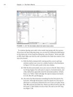
As illustrated in Fig. 12, the motion controller based on FPGA consists of modules such as
data instruction interface module, axis management module, digital PID module, T-curve
generation module, S curve generation module, data acquisition and processing module,
PWM module, synchronized module, and interrupt management module.
Date instruction
interface module
Synchronized
module
Interruper
management
module
X-axis
Management module
PWM
PWM
PWM
PWM
Feedback
Feedback
Feedback
Feedback
Interruper
signals
Bus signals
Y-axis
output
Encoder
and Hall
signals
Z-axis
Management module
Y-axis
Management module
N-axis
Management module
Z-axis
output
N-axis
output
X-axis
output
Fig. 12. The internal structure of motion controller
Low-level control algorithm is implemented as digital PID. The basic functions of the
controller include data cache, control algorithms, signal feedback, and PWM generation. The
controller is designed to control 18 DC servos motors in the robot joints.
6. Conclusions
The bionic cockroach robots have gone through a few generations over the past decades.
However their motion versatility and sensing and navigation abilities are still far from their
biological counterparts.
Bionic Limb Mechanism and Multi-Sensing Control for Cockroach Robots 103
One key aspect of bionic cockroach robots is multi-domain fusion approach towards bionic
mechanism design and motion smoothness control. It combines bionics, novel mechanism
and disperse adaptive control theory to realize harmonious bionic motion. Parallel
kinematic mechanism coupled with spring mechanism offers a realisable approach to
emulate the functions of cockroach legs
For a robot to mimic the powerful sensing and navigation abilities of a cockroach, a multi-
sensing fusion system has been proposed. It consists of binocular vision system based on
infrared imaging, and tactical sensors using fibre optic sensors and position sensitive
detectors.
The large amount of sensing information and real time motion control of 6-leg robots
require careful consideration of control system architecture. This paper has conceptualised a
distributed multi-CAN bus-mastering system based on Field Programmable Gate Array
(FPGA) and Advanced RISC Machine (ARM) microprocessor. The system architecture
provides stage treatment for control information and real-time servo control. It consists of
there core modules: (i) nodes of CAN bus servo drive, (ii) distributed multi-CAN bus-
mastering system based on FPGA, and (iii) software system based on ARM and Real-Time
Application Interface (RTAI).
A new chip called "smart brain chip" based on FPGA and SOPC technology has been
proposed to implement intelligent motion control for cockroach robot. It interfaces with
devices including motors, encoders, hall sensors; and execute low-level control algorithm
and smooth motion curve.
7. Acknowledgement
This work is supported by Natural Science Foundation of China under the research project
60775059, 863 Program of China under the research projects 2006AA04Z218, and
2008AA04Z210.
8. References
Karalarli, E.; Erkmen, A. M. & Erkmen, I. (2004). “Intelligent Gait Synthesizer for hexapod
Walking Rescue Robots”, Proc. of IEEE, Inter. Conf. on Robotics and Automation, pp.
2177 – 2182.
Bai, S. P.; Low, K. H. & Guo, W. M. (2000). “Kinematographic Experiments on Leg
Movements and Body Trajectories of Cockroach Walking on Different Terrain”,
Proc. of IEEE Inter. Conf. on Robotics and Automation, San Francisco, USA, pp. 2605 –
2610.
Quinn, R. D. & Ritzmann, R. E. (1998). “Construction of a Hexapod Robot with Cockroach
Kinematics Benefits both Robotics and Biology”, Connection Science, Vol. 10, No. 3,
pp. 239 – 254, 1998
Quinn, R. D.; Nelson, G. M.; Bachmann, R. J.; Kingsley, D. A. et al. (2003). “Parallel
Complementary Strategies For Implementing Biological Principles Into Mobile
Robots”, The Int. Journal of Robotics Research, Vol. 22, No. 3, pp. 169 – 186.
Schroer, R. T.; Boggess, M. J.; Bachmann, R. J. & Quinn, R. D. et al. (2004). “Comparing
Cockroach and Whegs Robot Body Motions”, Proceedings of the IEEE International
Conference on Robotics & Automation, New Orleans, pp. 3288– 3293.
Mobile Robots - State of the Art in Land, Sea, Air, and Collaborative Missions104
Quinn, R. D.; Kingsley, D. A.; Offi, J. T. & Ritzmann, R. E. (2004). “Automated Gait
Adaptation for Legged Robots”, IEEE Int. Conf. On Intelligent Robots and Systems,
Lausanne, Switzerland, pp.2652 – 2657.
Allen, T.J.; Quinn, R. D.; Bachmann, R. J. & Ritzmann, R.E. (2003). “Abstracted biological
principles applied with reduced actuation improves mobility of legged robots”,
Proc. of IEEE/RSJ Inter. Conf. of Intelligent Robots and Systems, Las Vegas, USA,
pp.1370 –1375.
Saranli, U.; Buehler, M. & Koditschek, D. E. (2000). “Design, Modeling and Preliminary
Control of a Compliant Hexapod Robot”, Proc. of IEEE, Inter. Conf. on Robotics and
Automation, pp. 2589 – 2586.
Moore, E.Z.; Campbell, D.; Grimminger, F. & Buehler, M. (2002). “Reliable Stair Climbing in
the Simple Hexapod 'RHex'”, Proc. of IEEE Int. Conf. on Robotics and Automation, pp
2222-2227.
Komsuglu, H.; McMordiey, D.; Saranlix, U. & Moore N. et al. (2001). “Proprioception Based
Behavioral Advances in a Hexapod Robot”, Proc. of IEEE, Inter. Conf. on Robotics and
Automation, pp. 3650-3655.
Weingarten, J. D.; Lopes, G. A. D.; Buehler, M. & Groff, R. E. et al. (2004) “Automated Gait
Adaptation for Legged Robots”, Proc. of IEEE Inter. Conf. on Robotics and Automation,
New Orleans, pp. 2153-2158.
Wei, T. E.; Quinn, R. D. & Ritzmann, R. E. (2004). “A CLAWAR That Benefits From
Abstracted Cockroach Locomotion Principles”, Inter. Proc. of Climbing and Walking
Robots Conference.
Boggess, M. J.; Schroer, R. T.; Quinn, R. D. & Ritzmann, R. E. (2004). “Mechanized
Cockroach Footpaths Enable Cockroach-like Mobility”, Proc. of IEEE, Inter. Conf. on
Robotics and Automation, New Orleans, pp. 2871-2876.
Kornbluh, R.; Kornbluh, R.; Pei, Q. & Stanford, S. et al. (2002) “Dielectric elastomer artificial
muscle actuators: toward biomimetic motion”, Proc. SPIE, Vol. 4695, pp 126-137.
Beer, R. D.; Quinn, R. D.; Chiel, H. J. & Ritzmann, R. E. (1997). “Biologically Inspired
Approaches to Robotics”, Communications of the ACM, Vol. 40, No. 3, pp.31 – 38.
Espenschied, K S.; Quinn, R D.; Beer, R D. & Chiel, H. J. (1996). “Biologically based
distributed control and locusl reflexes improve rough terrain locomotion in a
hexapod robot”, Robotics and Autonomous System, Vol. 18, pp. 59-64.
6
Biologically-Inspired Design of Humanoids
Xie M., Xian L. B., Wang L. and Li J.
School of Mechanical & Aerospace Engineering, Nanyang Technological University
Singapore
1. Introduction
Human beings are the most advanced creatures in the nature because of the combined
abilities of learning and performing both physical and mental activities. In terms of physical
activities, a human being is very skilful in undertaking both manipulation and biped
walking. And, in terms of mental activities, two impressive behaviours are analysis and
synthesis. Because of the mental power of doing analysis and synthesis, it is unique for
human beings to achieve discoveries and inventions. For instance, human beings have
gained a better understanding of the nature through a series of important discoveries, which
in turn fuel human being’s creativity leading to inventions. As result of human-made
inventions, our lives are much enjoyable than before.
Interestingly, among the human-made inventions, the most challenging one will be
humanoid robots (Hirai et al, 1998). One reason is that a humanoid robot is a unique
platform which integrates both complex manipulation (i.e. dexterous grasping and motions)
and complex locomotion (i.e. bipedal locomotion) (Ishida et al, 2004). Another reason is that
a humanoid robot is a unique platform which helps us to discover the physical principles
behind human-like skills and human-like intelligence (Xie et al, 2004). In the past twenty
years, we have seen many humanoid robot projects around the world. Among them, we can
mention HRP (Kaneko et al, 1998), BIP2000 (Espiau et al, 2000), ASIMO (Sakagami et al,
2002), QRIO (Ishida et al, 2004), HOAP (Kurazume et al, 2005) and HUBO (Kim et al, 2005).
In this chapter, we will discuss the issues behind the blueprints of a humanoid robot’s body,
brain and mind. Also, we will show examples of solutions to these important issues, which
are implemented on our LOCH humanoid robot.
2. Blueprint of Artificial Life
With the advance in mechanics, electronics, control, and information technology, it is
natural for people to dream of creating artificial life, which could possess a sophisticated
body, brain and mind (Xie, 2003). And, it is always the dream of human beings to create an
artificial life called robot, which could help us to perform dirty, difficult, or even dangerous,
jobs. Before we venture into the creating of artificial life, it is interesting to ask this question:
What is an artificial life?
Mobile Robots - State of the Art in Land, Sea, Air, and Collaborative Missions106
This is a difficult question. Only the designer of life is able to provide the full answer.
However, from an engineering point of view, we can identify the key steps which evolve
non-life into life.
Fig. 1. Five steps leading to artificial life.
Refer to Figure1. We believe that the evolution from non-life to life will go through the
following five key steps:
z Step 1: To be a dynamic system.
When a dormant body could respond to energy, such a dormant body will become a
dynamic system. In engineering, the use of actuators to drive a mechanism is a typical
example of creating a dynamic system which could respond to electric energy.
z Step 2: To be an automatic system.
When a dynamic system could respond to signal, such a dynamic system will become
an automatic system. By default, a dynamic system has its own transient and steady-
state responses when energy is applied to it as input. In order to control a dynamic
system for the purpose of achieving intended responses, it is necessary to create a
feedback mechanism so that a dynamic system will be able to directly respond to
signals, which in turn control the release of the energy. Such a feedback mechanism
can be called a behavioural Mind which plays the role of doing sensory-motor mapping.
z Step 3: To be an intelligent system.
When an automatic system could respond to knowledge extracted from signals, such
an automatic system will become an intelligent system. And, it is necessary to know
the principles behind the design of a cognitive Mind, which will have the ability of
extracting knowledge from signals such as visual or auditory signals.
z Step 4: To be an autonomous system.
When an intelligent system has the innate ability of making its own decisions and acts
according to its own decisions, such an intelligent system will become an autonomous
system. Therefore, an autonomous system must have a creative Mind which is able to
manipulate knowledge so as to synthesize decisions.
z Step 5: To be a conscious system.
Biologically-Inspired Design of Humanoids 107
Finally, when an autonomous system has a conscious Mind which is able to be aware of
any consequence of doing (or being) and not-doing (or not-being), such an
autonomous system will become a conscious system. When a dormant body reaches
the level of being a conscious system, we can say that a life or artificial life is born.
These five steps are important to guide discoveries in science and inventions in engineering.
For instance, the answer to the question of “what are the principles behind a human being’s
mind?” is yet to be discovered in science. And, the question of “how to create an artificial
mind which could extract knowledge from signals?” is still a big challenge in engineering.
3. Blueprint of Humanoid Robot
3.1 Blueprint of Body
In general, a humanoid robot’s body will consist of structure and mechanism (Kim et al,
2005). The purpose of structure is to house a humanoid robot’s computational modules,
communication modules, actuation modules and sensing modules. And, the main structure
will be located at the trunk of a humanoid robot. On the other hand, the purpose of
mechanism is to produce motions which in turn enable a humanoid robot to perform actions.
And, a mechnism is much more complex than a structure.
Since a humanoid robot has a human-like body, the blueprint of a humanoid robot’s body
will cover the mechnism of neck, the mechanism of arm, the mechnism of hand, the
mechanism of waist, the mechanism of leg and the mechanism of foot. And, the generic
design requirements for a humanoid robot’s body include:
1. The payload and degrees of freedom at the neck.
2. The payload and degrees of freedom at each arm.
3. The payload and degrees of freedom at each hand.
4. The payload and degrees of freedom at the waist.
5. The payload and degrees of freedom at each leg.
6. The payload and degrees of freedom at eah foot.
In order to enable a humanoid robot to perform human-like motions, the layout of degrees
of freedom and the angle ranges of these degrees of freedom must closely follow the
corresponding data of a human being. However, a human being’s body is a bio-mechanic
system, which has redundancy in kinematics. Therefore, it is necessary to do some
simplification. For instance, a humanoid robot’s neck may just have two degrees of freedom.
And, a humanoid robot’s waist is good enough to have two degrees of freedom as well.
In mechanics, a degree of freedom indicates an allowable motion between two rigid bodies
along, or about, an axis. In order to specify the orientation of an axis, it is necessary to define
a global reference coordinate system as shown in Figure 2.
Refer to Figure 2. The global reference coordinate system is placed on a ground. The Z axis
is perpendicular to the ground. The rotation about Z axis is called Yaw. The Y axis is in the
coronal plane of a humanoid robot. The rotation about Y is called Pitch. And, the X axis is
the in sagittal plane of a humanoid robot. The rotation about X axis is called Roll.
Mobile Robots - State of the Art in Land, Sea, Air, and Collaborative Missions108
Fig. 2. Definition of reference coordinate system and (Yaw, Pitch, Roll).
In practice, a humanoid robot may have a distribution of degrees of freedom as follows:
a) Neck: Two degrees of freedom.
b) Arm: Six degrees of freedom so that the wrist can be in any orientation.
c) Hand: Ten degrees of freedom in total, and two degrees of freedom per finger.
d) Waist: Two degrees of freedom.
e) Leg: Six degrees of freedom so that the ankle can be in any orientation.
f) Foot: One degree of freedom.
Figure 3 shows a typical layout of the degrees of freedom in a humanoid robot.
Fig. 3. Layout of degrees of freedom in a humanoid robot.
Biologically-Inspired Design of Humanoids 109
We can see that the orientations of these degrees of freedom are as follows:
1. Neck: (Yaw, Pitch)
2. Arm: (Pitch, Roll, Yaw) at shoulder; Pitch at elbow; (Pitch, Yaw) at wrist.
3. Hand: (Yaw, Pitch) at thumb; (Pitch, Pitch) at other fingers.
4. Waist: (Yaw, Roll)
5. Leg: (Pitch, Roll, Yaw) at hip; Pitch at knee; (Roll, Pitch) at ankle.
6. Foot: Pitch.
3.2 Blueprint of Brain
In a human being’s brain, there are: a) cerebrum and b) cerebellum. The cooperation of these
two organs makes a human being extremely powerful in undertaking: a) knowledge-centric
activities and b) skill-centric activities. Interestedly, the knowledge-centric activities are
orchestrated by the cerebrum. And, the neural system in the cerebrum is divided into
different zones, each of which has a specific function such as speech, vision, reading,
writing, smelling, reasoning, etc.
On the other hand, the skill-centric activities are controlled by both the cerebrum and the
cerebellum. For instance, the cerebrum controls the skill-centric activities at the cognitive
level, such as: planning, coordination, and cooperation. And, the cerebellum controls the
skill-centric activities at the signal level with a network of feedback control loops, each of
which consists of: a) sensing neurons, b) actuating neurons and c) control neurons.
In engineering terms, a human brain can be treated as a distributed system with two main
controllers and many sub-controllers. Therefore, the blueprint of a humanoid robot could
follow such a design, which is based on a network of distributed microcontrollers under the
supervision of two main host computers, as shown in Figure4.
Fig. 4. A network of distributed microcontrollers and two main computers.
Refer to Figure4. Each microcontroller has the abilities to do: a) sensing, and b) control. And,
each of the main computers will have the built modules for wired and wireless
Mobile Robots - State of the Art in Land, Sea, Air, and Collaborative Missions110
communications, which will enable a humanoid robot to act and interact with human beings
or other humanoid robots.
3.3 Blueprint of Mind
A human being has a powerful mind, which enables him/her to perform both mentally and
physically challenging activities. Also, it is interesting to note that a human being’s mind is a
composite mind which consists of: a) behavioral mind, b) cognitive mind, c) creative mind
and d) conscious mind.
In engineering terms, a behavioral mind is responsible for the control and coordination of
skill-centric activities such as grasping, manipulation, walking, and running, etc. And, the
basic principle behind a behavioral mind is the feedback control mechanism.
For a humanoid robot, the coordinated control of the motions at the joints will give rise to a
complex behavior. And, at each, there are two types of motion: a) unconstrained motions
and b) constrained motions. Therefore, at each joint, there must be three feedback control
loops such as a) position control loop, b) velocity control loop and c) torque control loops as
shown in Figure 5.
Fig. 5. Behavioral mind consisting of feedback control loops at the joints.
In Figure 5,
),,(
ddd
WTT
is a set of desired joint angle, desired joint velocity and desired joint
torque. And,
)(i
g
W
is the torque for gravity compensation by joint i.
Due to the advance in control engineering, the principle behind a behavioural mind is well-
understood. However, it is still a challenging to discover the principles behind a cognitive
mind, a creative mind and a conscious mind.
It is worthy noting that there is no significant progress in artificial intelligence, despite the
huge amount of research efforts devoted to this field and other related fields such as
cognitive sciences, machine learning, and natural language processing. This stagnation is
largely due to the lack of clear statements of the fundamental questions to be faced by
Biologically-Inspired Design of Humanoids 111
artificial intelligence. People fail to clearly define such fundamental questions because the
main focus of the actual research efforts is on the so-called computer-aided human intelligence,
which is real and not artificial. And, the typical example of such endeavour is the IBM’s
deep blue project, in which the computer has no intelligence at all.
Here, we believe that artificial intelligence literally means the self-intelligence in robots or
machines. Therefore, the fundamental questions to be faced by artificial intelligence include:
z What is the physical principle behind the transformation from visual signals into the
cognitive state of knowing the meanings behind these signals? And, how to
implement this physical principle onto a robot or machine?
z What is the physical principle behind the transformation from auditory signals into
the cognitive state of knowing the meanings behind these signals? And, how to
implement this principle onto a robot or machine?
z What is the blueprint behind the representation of learnt meanings? And, how to
implement this blueprint onto a robot or machine?
z What are the processes and their working principles, which manipulate the learnt
meanings for various activities related to knowledge and skill?
It is interesting to note that human mind is implemented onto a human brain, which has a
neural architecture. In addition, a human mind is very powerful in undertaking both
knowledge-centric activities and skill-centric activities. However, these two types of
activities are very different. Then, we may ask this fundamental question: What are the models
behind a neural architecture, which share a same hardware infrastructure?
In (Xie et al, 2004), we first show that the mathematical principle behind a neural network
and hidden Markov model has the root on the state space equation, which describes the
dynamic behaviours of any dynamic system. In other words, the model of a neural
architecture for skill-centric activities is rooted on the state space equation.
Also, in (Xie et al, 2004), we outline a meaning centric framework for the representation of
learnt meanings. We believe that a natural language is the best solution of knowledge
representation. The evidence is our libraries, in which all learnt knowledge is documented
in natural languages. Therefore, one crucial issue in artificial intelligence is: what is the
universal principle for a human mind to represent a natural language?
Here, we advocate a concept-physical principle for the representation of a natural language,
as shown in Figure 6, in which the main features are:
1. Meanings can be divided into two levels: a) the elementary meanings and b) the
composite meanings.
2. A real world is composed of two related worlds, namely: a) physical world and b)
conceptual world.
3. A physical world exists because of the existence of physical entities, which include
nature-made objects and human-made objects.
4. A conceptual world exists because of the existence of conceptual entities, which
include the words in natural languages.
5. The elementary meanings in the physical world refer to the properties and constraints
of the entities in the physical world, while the elementary meanings in a conceptual
world (note: each natural language depicts one conceptual world) refer to the
properties and constraints of words in a conceptual world.
6. Each physical entity has at least one corresponding word in a conceptual world.
Mobile Robots - State of the Art in Land, Sea, Air, and Collaborative Missions112
7. Each property of a physical entity has at least one corresponding word in a conceptual
world.
8. Each constraint of a physical entity has at least one corresponding word in a
conceptual world.
9. Interactions among the physical entities due to the constraints will create the
composite meanings such as configurations, behaviours, events and episodes.
10. Interactions among the conceptual entities due to the constraints will create the
composite meanings such as phases, sentences, concepts and topics.
Fig. 6. Knowledge representation by meaning network.
In Figure 6, we have clearly defined what the knowledge (i.e. meanings) is. And, features 6,
7 and 8 solve the important problem of symbol grounding faced by the old paradigm for the
study of natural language understanding.
Biologically-Inspired Design of Humanoids 113
Fig. 7. Scheme of conversational dialogue with a natural language.
With the implementation of such a meaning network as shown in Figure 6, it becomes
possible for robots to learn and converse in human language, insead of making human
beings to continue to learn and program in machine language. Most importantly, the ability
of undertaking conversational dialogues with a natural language, as shown in Figure 7, will
be a decisive step for humanoid robots to be deployed into home enviroment for various
services.
In summary, the blueprint of a human-like mind is two fold. First of all, the model for skill-
centric activities is rooted on state space equation, which is effective in describing the
dynamic response of any dynamic system. Second, the model for knowledge-centric
activities is rooted on meaning network, which enables a range of mental processes to do
jobs such as learning, analysis, synthesis, understanding, decision-making, and inference.
4. Design Considerations
When we implement the generic blueprints of body, brain and mind, we must consider
several issues which may not be trivial.
4.1 Actuation by the Principle of Many-to-Many Coupling
Although it is relatively easy to choose materials and to size the motors during the detailed
design of a humanoid robot’s body, the issue of actuation is generally overlooked. One
reason is because many researchers and engineers believe that the solution to actuate a joint
is simply to use an actuator. However, careful analysis will revieal that there are different
ways of actuating the joints in a body.
Mobile Robots - State of the Art in Land, Sea, Air, and Collaborative Missions114
For instance, a human body’s skeleton is actuated by musles. And, it is interesting to note
that some joints are actuated by multiple muclses in order to achieve the redundancy in
actuation. In this case, when one mucle faces a problem, a joint will not be handicaped in
general. Such a scheme of coupling many muscles with many joints is useful in achieving
reliable actuation. In engineering terms, the idea of coupling many actuators with many
joints can be depicted in Figure 8.
Fig. 8. Actuation scheme of coupling many actuators with many joints.
Another example is to use a single actuator to independently drive many joints in a robot
(Zhu et al 2000; Xie, 2003). Such a scheme of coupling one actuator with many joints is useful
if we want to reduce the weight and cost.
Unfortunately, today’s robots are still follow the old scheme of coupling one actuator with
one joint. This scheme has the least reliability. When one actuator fails, a joint will
systematically fail. As a result, a robot will fall as shown in Figure 10, in which the knee joint
of the robot’s right leg fails during the climbing of staircase.
Fig. 9. Failure due to actuation scheme of coupling one actuator with one joint.
Biologically-Inspired Design of Humanoids 115
In engineering terms, the idea of coupling one actuator with one joint is simple to be
implemented. Figure 10 illustrates the actuation scheme of coupling one actuator with one
joint.
Fig. 10. Actuation scheme of coupling one actuator with one joint.
4.2 Foot with Variable Length
A human being’s foot is not a single rigid body. It has at least one pitch joint (Bruneau, 2006).
Interestingly, such a design enables a foot to have a variable foot length, which in turn will
have two advantages.
First of all, a larger foot helps increase the stability of a humanoid robot during standing or
walking. Second, a smaller foot (i.e. a shorter foot length) helps a humanoid robot to
run/jump at ease. As shown in Figure 11, when a humanoid robot is lifting up the body, the
lifting force comes from the torque at the ankle joint (or knee joint). From the relationship
between force and torquem, it is clear that the shorter the foot length is, the larger the lifting
force will be, when the torque remains the same.
Fig. 11. A variable foot length helps generate larger lifting force.
Similarly, when a humanoid robot lands with a same impact force, the shorter the foot
length is, the smaller the impact torque at the ankle joint will be.
In pratice, we can design a humanoid robot’s foot with two rigid bodies. When a humanoid
robot’s foot consists of two links with the lengths of ),(
21
ll , the foot could have three
possible configurations of length, such as: a)
21
ll , b)
1
l , and c)
2
l .