Mobile Robots book 2011 Part 4 pptx
Bạn đang xem bản rút gọn của tài liệu. Xem và tải ngay bản đầy đủ của tài liệu tại đây (2.97 MB, 25 trang )
Mobile Robots - State of the Art in Land, Sea, Air, and Collaborative Missions66
which have more than one conductor per phase, there are even more obstacles such as
spacers and spacer dampers (Figure 1)
1
.
The robot travels suspended from the conductor and has to cross obstacles along the power
line that requires complex robotic mechanisms including conductor grasping systems and
robot driving mechanisms. Moreover, an obstacle detection and recognition system, robot
control system, communication, inspection platform equipped with necessary sensors and
measurement devices, power supply and electromagnetic shielding have to be considered in
robot mechanism design and construction.
Fig. 1. Different obstacles on power line conductors: (a) suspension insulator, (b) strain
insulator, (c) damper, (d) spacer/spacer damper (e) aircraft warning sphere (Katrasnik et al.,
2008).
3.2 Cable-climbing mechanisms designed over the past 20 years
One of the first cable-climbing mechanisms presented in (Aoshima et al., 1989). The
proposed mechanism, which was designed for telephone lines inspection, compared to its
previous works is able to transfer to branch wires, and thus provides more flexibility in
cable-climbing. The robot structure, as shown in Figure 2, consists of a multi-unit of six
identical modules with three degrees of freedom: longitudinal movement on the cable,
horizontal rotation about robot’s longitudinal axis parallel to the power line, and vertical
elongation of robot’s arms.
Fig. 2. Proposed cable-climbing mechanism in (Aoshima et. al., 1989).
1
All of the figures and tables used in this literature survey have been taken from the original works presented by
their authors.
Cable-Climbing Robots for Power Transmission Lines Inspection 67
Using different configuration of these six units, the robot will be able to adapt itself to
different geometrical environments and avoid obstacles with different shapes and sizes,
transfer to a branch wire, and even transfer to a parallel line. As an example to show the
flexibility of the proposed mechanism by Aoshima et al., Figure 3 describes how the robot
transfers to a branch wire. The proposed robot has good maneuverability over different
obstructions and variety of different geometrical environments on the power lines, but as
Figure 3 shows, the robot is complex in control.
One of the first efforts towards designing a more simple cable-climbing mechanism carried
out by (Sawada et al., 1991) to inspect fibre-optic overhead ground wires (OPGWs). The
proposed robot, as shown in Figure 4, consists of a vehicle assembly to navigate on the
power line, an arc shape guide rail, a guide rail manipulator, and a balancer with controller
to pass the obstacles. It can travel on slopes of up to 30º. When the robot comes across an
obstacle, it opens its rail and hangs it on the line on both sides of the obstacle. Then the drive
mechanism detaches from the conductor and travels on the rail to the other side of the
obstacle. Utilizing such an obstacle avoidance mechanism, the robot is able to negotiate
towers as well and transfer to the next span to inspect rest of the power line.
Fig. 3. How the multi-unit robot transfers to a branch wire (Aoshima et al., 1989)
The proposed robot did not have proper shielding for live line inspection and could not
travel on phase conductors. Moreover, stability issues in windy climates and slow obstacle
Mobile Robots - State of the Art in Land, Sea, Air, and Collaborative Missions68
overcoming mechanism, for example, spending 15 minutes to overcome each tower, were
unresolved issues in the proposed robot.
Fig. 4. Basic configuration of proposed mechanism in (Sawada et al., 1991)
Fig. 5. How Sawada and his colleagues’ robot passes the towers (Sawada et al., 1991).
In the same year, a project with same purpose was done by Higuchi et al. The proposed
stride type robot, as shown in Figure 6, can move on a ground wire stretched on top of the
towers and is also able to pass the towers (Higuchi et al., 1991). The robot can navigate on
the overhead ground lines using two arms to take steps and a crawling mechanism to move
on top of the towers (Figure 7).
The presented work has the stability problems in windy climates and is also more complex
to control than the work in (Sawada et al. 1991). In addition, as Figs. 6 and 7 show, the
design is specific for inspection of the overhead ground wires stretched on top of the towers
with a flat area on top and cannot be used as a general inspection robot for all types of the
power lines. For instance, the robot cannot pass the towers when it is traveling on phase
conductors as the robot is not able to overcome the insulators.
To achieve both stability in movement and simplicity in control, another project ran by
Tsujimura and Morimitsu in 1997 to make a cable-climbing robot for the telecommunication
lines inspection. The proposed robot in (Tsujimura & Morimitsu, 1997) and the locomotion
principle have been shown in Figs. 8 and 9. A linkage mechanism creates a gait
kinematically and causes the arms to hang on the cable at intervals. The robot walks parallel
to the cable and as it moves, due to the nature of the movements, can avoid obstacles as
well.
Cable-Climbing Robots for Power Transmission Lines Inspection 69
Fig. 6. Architecture of the robot proposed by (Higuchi et al., 1991)
Fig. 7. Sequence of going over the tower in (Higuchi et al., 1991)
Mobile Robots - State of the Art in Land, Sea, Air, and Collaborative Missions70
Fig. 8. Proposed cable-climbing mechanism in (Tsujimura & Morimitsu, 1997)
The proposed mechanism can provide constant moving speed, which is ideal for inspection, is
simple to do, stable, and simple to control, but cannot transfer to the angled lines.
(a)
(b)
Fig. 9. Locomotion principle of the proposed mechanism in (Tsujimura & Morimitsu, 1997)
(a) linkage that provides gait movement and (b) simulation of movements of one of the
robot’s arms
Meanwhile, some researchers focused on making fully operational robots to carry out
special tasks on the power lines, even though they were not able to perform the task fully
autonomously. One such robot was presented by Campos et al. in 2002. The proposed robot,
shown in Figure 10, is a simple but operational cable-climbing mechanism for installation
and removal of the aircraft warning spheres. This robot can only navigate on part of the line
between two towers without avoiding any obstacle. Similar mechanisms, shown in Figs. 11
Cable-Climbing Robots for Power Transmission Lines Inspection 71
and 12, can be found in (Sato Ltd., 1993) and (Cormon Ltd, 1998), respectively. The proposed
mechanisms consist of a trolley with two pulleys on top that can move the trolley and all the
required manipulators and the inspection tools. The mechanisms proposed by Campos et
al., Sato Ltd., and Cormon Ltd. have been tested in real working conditions and the two
latter are commercially available. Although these robots are not able to pass the obstructions
on the power lines or transfer to the next span, they are simple and operational.
Fig. 10. The aircraft warning sphere installation and removal mechanism proposed in
(Campos et al., 2002)
Fig. 11. Automatic overhead power transmission line damage detector developed by (Sato
Ltd., 1993).
Fig. 12. Mobile corrosion detector proposed in (Cormon Ltd., 1998)
Some more throughput mechanisms were developed in 2004. One of these mechanisms has
been shown in Figure 13. This figure shows a sketch of the mechanical mechanism designed
by (Tang et al., 2004). The proposed robot has two front and rear arms and a body. There is a
gripper on top of each arm and a running wheel on top of the body. In addition, using
Mobile Robots - State of the Art in Land, Sea, Air, and Collaborative Missions72
wheels in the gripper design have enabled this robot to move along the line back and forth
even when the grippers grasp the line.
Fig. 13. Proposed mechanism by (Tang et al., 2004)
Fig. 14. Proposed obstacle navigation procedure in (Tang et al., 2004)
The obstacle navigation process is shown in Figure 14. When the robot detects an obstacle,
the rear arm gripper grasps the line, and the front arm elongates to pass the obstruction. In
the second step, the front arm gripper grasps the line, and the running wheels get off from
the wire. Next, the two grippers continue to move forward, and consequently the body can
move across the obstacle. Finally, the running wheel turns over the wire and grasps it, the
rear arm gripper is detached from the line and pass the obstacle. Considering different
distances between two consecutive obstacles and different tower sizes in mechanism design,
the proposed robot can pass all types of the obstacles on straight lines autonomously.
Cable-Climbing Robots for Power Transmission Lines Inspection 73
Similar crawling mechanism also proposed by (Wolff et al., 2001), and modified by
(Nayyerloo et al., 2007). In the latter, a mechanical mechanism, as shown in Figure 15, was
proposed. The mechanism has three similar grippers mounted on top of three arms, which
can go up and down. These three independent grippers make the robot able to be fixed to
the line or move along the line easily when it is hung from the line. Two motors in the
driving system mounted on top of the middle arm drive the whole robot. The front and rear
arms can move along the robot length synchronously using the arm driving mechanism and
two connection rods, which have connected these two arms together. The middle arm is
fixed to the robot body.
The proposed arm driving mechanism plays two roles for the robot: translation of the front
and rear arms along the robot length and translating the robot itself. The front and rear arms
have been mounted on two nuts of a main screw, which represents the robot body. If the
main screw is driven while the middle gripper has been clamped to the line, both movable
arms will move along the line together. In a same way, there is another possibility to fix two
movable arms to the line and drive the screw to move the robot body.
Fig. 15. Proposed mechanism by Nayyerloo et al., 1) the gripping mechanism, 2) the driving
system, 3) one of the three arm mechanisms, and 4) the arm driving mechanism (Nayyerloo
et al., 2007)
When the robot detects an obstruction, the gripper of the closest arm to the obstacle opens,
and the arm goes down to avoid contact. The next step is translating the arms forward by
fixing the middle arm to the line and driving the robot’s main screw to pass the front arm to
the other side of the obstacle. When the front arm passes the obstacle, it goes up and grips
the line on the other side of the obstruction (1-3 in Figure 16). At this stage, the robot needs
to make enough room on the other side of the obstacle to transfer the middle arm. This will
be done by fixing the front and rear arms’ grippers to the line and driving the main screw to
move the middle arm as close as possible to the obstacle, and then fixing the middle arm to
the line and moving the front and rear arms forward (4 and 5 in Figure 16). To transfer the
middle arm to the other side of the obstacle the front and rear arms’ grippers grasp the line,
the middle gripper is detached from the line, the middle arm goes down, and the main
screw is driven to move the middle arm under the obstruction. The middle arm grasps the
line on the other side of the obstacle and makes the robot stable to pass the rear arm (6 and 7
in Fig 16). Following the same concept, the rear arm passes the obstacle, and the robot
returns to its original configuration.
Mobile Robots - State of the Art in Land, Sea, Air, and Collaborative Missions74
(5)
(1)
(6)
(2)
(7)
(3)
(4)
Fig. 16. Obstacle traversing mechanism proposed in (Wolff et al., 2001) and (Nayyerloo et
al., 2007)
The proposed mechanism is simple to control, fast, and stable in overcoming obstacles. Even
in windy climates, the three flexible arms can lift the robot body and make it as close as
possible to the line to avoid swinging with large amplitudes. Another interesting feature of
the proposed mechanism is its capability to navigate on paths with different shapes i.e. the
robot’s path could be even non-parabolic. The lengths of the robot arms can be adjusted
according to the slope of the navigating path to keep the robot horizontal in all situations
during the movement. The robot also has three hinged joints at the end of each arm that
allow the grippers to be adjusted according to the slope of the line i.e. only grippers are
Cable-Climbing Robots for Power Transmission Lines Inspection 75
sloped and the arms remain vertical in all situations. Besides the advantages of the proposed
mechanism, it still needs to be modified to be able to pass tension towers with angled lines.
Another interesting obstacle traversing mechanism for power lines inspection robots
proposed by (de Souza et al., 2004). The obstacle overcoming procedure is shown in Figure
17. The configuration in this figure has two sets of three wheels to move the robot along the
line. When the robot detects an obstacle following obstacle avoidance procedure is followed:
the box in middle of the robot, which contains all the required inspection tools, moves back
along the track, the front set of wheels releases the line and rotates, the rear set of wheels is
moved to surpass the obstacle (1 in Figure 17), and the front set of wheels grips the cable on
the other side of the obstacle. Next, the box is moved forward to the other end of the track,
the rear set of wheels releases the line and rotates then the robot moves until the rear set of
wheels surpasses the obstacle (2 in Figure 17). The rear wheel set grasps the line again, and
the robot goes back to its original configuration (3 in Figure 17). The same concept in
obstacle overcoming mechanism, as shown in Figure 18, was also used by Sun et al. (Sun et
al., 2006), but without centroid adjustment. In this work, the authors tried to optimize the
mechanism design through using some simulation and analysis software's such as Pro/E
and ANSYS. Thus, both designs are simple, stable, and fast in obstacle avoidance, but they
apparently cannot pass the tension towers and transfer to angled lines. Moreover, such
mechanisms should be modified to be able to overcome the obstructions such as warning
spheres, which have more protrusion from the line than the clamps.
Another interesting cable-climbing mechanism, which is similar to the works in (de Souza et
al., 2004) and (Sun et al., 2006) with a modification in arms movement, was presented by Fu
et al. in 2006. Their inspection robot, shown in Figure 19, has two arms with driving wheels
mounted on top of each arm. The arms can go up and down, and the driving wheels, which
are combined with a gripper mechanism to grasp the line when it is required, can move the
robot along the line. When the robot encounters an obstacle ahead, the main body is moved
forward to balance the robot’s weight according to the front arm position. Next, the rear arm
raises its driving-gripping set from the line, passes the obstacle, and lowers down to grasp
the line on the other side of the obstacle. To pass the front arm to the other side of the
obstacle, the robot needs to balance its weight according to the rear arm position. Next, the
front arm releases the line, goes up, and passes the obstacle. In this procedure, the rear arm
becomes the front arm and vice versa. When the both arms pass the obstacle, the robot
should go back to its original configuration again (Fu et al., 2006).
(1)
Mobile Robots - State of the Art in Land, Sea, Air, and Collaborative Missions76
(2)
(3)
Fig. 17. Obstacle traversing mechanism proposed in (de Souza et al., 2004)
Fig. 18. From left to right, obstacle overcoming process in (Sun et al., 2006)
Fig. 19. The cable-climbing robot presented in (Fu et al., 2006)
Similar work to the project accomplished by Fu et al. has been recently carried out by Ren
and Ruan. As shown in Figure 20, similar method has been used for navigation and obstacle
traversing in (Ren & Ruan, 2008). These two mechanisms can only pass obstructions with
small protrusion from the line such as different kinds of clamps and dampers, and more
importantly, these two mechanisms cannot transfer to the angled lines.
Cable-Climbing Robots for Power Transmission Lines Inspection 77
(1) (2) (3)
(4) (5)
Fig. 20. Obstacle traversing mechanism proposed in (Ren & Ruan, 2008).
One of the most simple and efficient mechanisms, which resolves some of the issues in (Fu
et al., 2006) and (Ren & Ruan, 2008), proposed by Zhu et al. in 2006. The robot configuration,
as shown in Figure 21 (a) and (b), has two arms equipped with a special gripper combined
with a driving wheel. This special running-gripping mechanism has been shown in Figure
22. When the robot detects an obstacle on its way, it stops, grasps the conductor with the
front gripper and moves its main body under the front arm in order to minimize the
required torque needed for crossing the obstacle (Figure 23 (a)). Next, the rear arm lifts the
rear running wheel up, and the front arm rotates the whole robot around its own axis.
Finally, the rear arm lowers its wheel set on the conductor (Figure 23 (b)), and then the same
process is repeated with the arms' roles changed. Such an obstacle traversing strategy makes
the robot’s arms simple with only two degrees of freedom. Also the required torques in the
joints and on the line will be small enough, thus there is no need for the heavy and powerful
motors.
(a) (b)
Fig. 21. Robotic mechanism configuration proposed by Zhu et al.: (a) sketch of the robot's
configuration, and (b) the robot prototype (Zhu et al., 2006)
Mobile Robots - State of the Art in Land, Sea, Air, and Collaborative Missions78
Fig. 22. Special running-gripping mechanism proposed in (Zhu et al., 2006)
Fig. 23. Obstacle avoidance procedure proposed by Zhu et al. (Katrasnik et al., 2008)
The proposed mechanism is simple, stable and efficient. Moreover, with some minor
modifications in the gripper design to increase the contact area between the gripper and the
line, the robot will be even more stable in windy climates. Another interesting feature that
the proposed mechanism can provide with minor changes in the existing gripper design is
the ability to transfer to angled lines. The robot rotation angle about the arms’ axes in the
obstacle avoidance procedure can be adjusted to the angle of the line ahead, thus the robot
can easily transfer to an angled line, but as in this situation, the grippers are not parallel to
each other, they should be able to rotate about the arms’ axes to be able to adjust themselves
to the line angle.
The mechanism has a minor disadvantage that should be taken into account when dealing
with acquired inspection or navigation data. When the robot passes an obstacle, it has to
rotate 360° around the arms’ axes. Hence, the installed inspection or navigation sensors on
the robot body, such as image system, will rotate 360° under the obstacle to pass it. This
rotation in the robot main body has been missed out in both the original work and
(Katrasnik et al., 2008). It therefore has not been shown in Figure 23, which has been taken
from the latter work. This rotation may cause some undesirable inspection or navigation
data.
One of the most important efforts to develop an operational cable-climbing mechanism has
been made by Montambault and Pouliot over the past five years. Their teleoperated robot,
Cable-Climbing Robots for Power Transmission Lines Inspection 79
LineScout, shown in Figure 24, is the third generation of its previous prototypes designed by
this team. LineScout uses driving wheels for locomotion. These wheels allow the robot to
not only move quickly along the power line, but also to roll over some obstacles e.g.
compression splices and vibration dampers. To clear other types of obstacles, the robot
follows the approach schematized in Figure 25 (a). As shown in this figure, LineScout has
three independent frames: the wheel frame (dark frame), which includes two motorized
wheels called “traction wheels”, the arm frame (light frame), with two arms and two
grippers, and the center frame (white circle), which is called “extremity frame”. This frame
links the first two frames together and allows them to slide and pivot (Montambault &
Pouliot, 2007). As an obstacle is detected, the arm frame is opened, and its two arms and
grippers temporarily support the robot while the wheel frame is being transferred to the
other side of the obstacle with the wheels flipped down under the obstacle. The wheel frame
also includes a pair of safety rollers (small rectangles beside the driving wheels) for platform
stability when crossing obstacles. The center frame supports the electronics cabinet and
battery pack. The role of the center frame is generating the movements of the two other
frames by sliding them in opposite directions and also supporting about 40% of the
platform’s weight to minimize the cantilevered load applied when the two other frames are
in total extension during the obstacle clearance sequence as shown in top picture in Figure
25 (b).
Although the appropriateness of the proposed line inspection robot has been shown
through several lab and field tests for straight lines between suspension towers, the
mechanism still needs to be modified to be able to pass the tension towers with angled lines.
However, it surpasses all its previous designs in terms of considering different real field
requirements such as resistance to intensive electro-magnetic field and durability of the
inspection task that are vital toward having an operational inspection robot.
In order to decrease the above mentioned complexities in designing a versatile cable-
climbing mechanism capable of clearing all types of the obstructions and able to transfer to
the angled lines on various power transmission lines, a new type of robot proposed by
Katrasnik et al. in 2008 (Katrasnik et al., 2008). The idea is based on the combination of a
flying robot such as (Williams, 2000) or (Golightly & Jones, 2005) with a cable-climbing robot
to navigate on the power lines. The proposed flying-climbing robot, schematized in Figure
26, removes all the complexities in the mechanical mechanism design arising from the
obstacle avoidance system by flying over the obstacles or flying from one span to another
span to pass the towers. The implemented cable-climbing mechanism, which is the default
navigation system of the robot on the line between the obstacles, ensures stability in
navigation and provides performing the inspection from close distances to the line that is
necessary for various line inspection sensors such as corrosion detectors. Using the climbing
mechanism as the default navigation system also removes the flight control complexities in
existing flying inspection robots when the robot navigating between the obstacles.
Mobile Robots - State of the Art in Land, Sea, Air, and Collaborative Missions80
Fig. 24. LineScout mobile platform (Montambault & Pouliot, 2007).
(a) (b)
Fig. 25. LineScout obstacle-clearing sequence: (a) schematic of the obstacle-clearing
procedure (Pouliot & Montambault, 2008) and (b) LineScout clearing obstacles in real
working conditions (Montambault & Pouliot, 2007)
Fig. 26. Flying-Climbing robot (Katrasnik et al., 2008)
Katrasnik et al. have compared the two possibilities in the power lines inspection robot
design, flying and climbing, with their novel mechanism proposed in (Katrasnik et al., 2008).
The results are shown in Table 1. As the table shows, four major criteria have been chosen
for this comparison: Availability and simplicity of the robot’s design and construction,
quality of the acquired inspection data, fully autonomous inspection, and adaptability to
different situations on the power lines or universality. The comparison criteria have been
Cable-Climbing Robots for Power Transmission Lines Inspection 81
sorted in order of importance and appropriate weight, as shown in Table 1, has been given
to each criterion.
w Climbing Climbing-Flying Flying
Design and Construction 4 1|4 2|8 3|12
Inspection quality 3 2|6 3|9 1|3
Autonomy 2 3|6 2|4 1|2
Universality 1 1|1 2|2 3|3
Total score 17 23 20
w=weight, rank | weighted score
Table 1. Robot type comparison table (Katrasnik et al., 2008)
Various types of unmanned aerial vehicles (UAVs) are commercially available, and there is
no need to start from scratch and build a new flying platform for inspection of the power
lines. Hence, the highest point in the first criterion has been given to the flying robot. Also
with some modifications on available UAVs in the market, the climbing-flying robot is
achievable, thus the second highest scored design is the climbing-flying robot.
To compare the inspection data quality, the most problematic case is the flying robot
(Katrasnik et al., 2008). Vibrations of the flying platform and its distance to the power lines
during the inspection affect quality and resolution of the captured images, which are the
main inspection data. The climbing mechanism has less vibration than the flying robot due
to the line support and has been ranked higher than the flying robot. The climbing-flying
robot can inspect the line equipment (obstacles) from additional angles when it flies over
them. In that, the highest grade has been given to the climbing-flying robot.
In terms of autonomy, due to complexity of the flight control, making a fully autonomous
flying robot is certainly more difficult than developing an autonomous climbing mechanism.
Moreover, when the robot is attached to the power line, the required power can be supplied
through the live-line that makes the robot more independent and autonomous.
The last evaluation item in Table 1 is the universality of these three mechanisms. The flying
robot is completely unattached to the power lines, and thus has more maneuverability over
different power lines. The climbing-flying robot needs some modifications in the climbing
side to be adapted to different conductor sizes, but the climbing robot needs major
modifications especially to be able to pass different obstacles. In that, the highest score has
been given to the flying robot, followed by the flying-climbing mechanism, and the lowest
scored design in terms of universality is the climbing robot.
4. Conclusions
Uninterruptable electricity supply to a vast number of customers has utmost importance for
power companies. Therefore, regular live line inspection is a vital task for the power
companies to find damage to the line to prevent likely blackouts. The most desirable
inspection method in dangerous live-line environment is certainly a fully autonomous
method without human operator intervention.
Traditional patrol inspection using helicopters is costly, do not provide a platform for
precise inspection of the line from close distances, and due to the risk of contact with the live
line in windy climates still is not sufficiently safe for the operators. In that, researchers have
endeavored to build robots capable of performing the live line inspection autonomously.
Mobile Robots - State of the Art in Land, Sea, Air, and Collaborative Missions82
Unmanned aerial vehicles and cable climbing robots are the two main categories of the
power line inspection robots. UAVs are complex in control and do not provide an
appropriate platform for internal inspection of the conductors. For instance, corrosion
detector sensors, which examine the line from a close distance, cannot be used on such
platforms. However, as UAVs fly over the power lines, their design is not directly
dependent on geometrical characteristics of the lines. Moreover, these flying robots have
been already commercialized and can be modified for live line applications. The second
main category, the climbing robots, are much more dependent on the line equipment than
the flying robots in terms of size and shape of the obstacles on the lines, surrounding
electromagnetic field, voltage level of the line, etc.
Climbing robots should be specifically designed for the power lines from scratch. They are
not currently available on the market, but they provide more autonomy and inspection data
quality. The climbing platforms also allow more accessibility to variety of inspection sensors
than the flying robots. This unique feature has been made research in the cable-climbing
mechanism design popular.
This chapter reviewed some of the main efforts made over the past 20 years in the field of
cable-climbing mechanism design to provide a basis for future developments in this field.
History of the research in this field shows that due to the huge benefit of early detection of
likely damage to the line, even the cable-climbing robots capable of only climbing on part of
the line between two obstacles are in use, and further researches in this field will definitely
benefit the power companies to efficiently manage their assets. In addition, based on the
reviewed works, a flying-climbing platform which is a commercially available UAV
modified with a cable-climbing mechanism would enormously benefit the line inspection
quality and the design universality.
5. References
Aggarwal, R. K.; Johns, A. T.; Jayasinghe, J.A.S.B. & Su, W. (2000). An overview of the
condition monitoring of overhead lines, Electric Power Systems Research: An
International Journal, No. 53, 2000, pp. 15-22, Elsevier Science S.A., PII: S0378-
7796(99)00037-1
Aoshima, S.; Tsujimura, T. & Yabuta, T. (1989). A wire mobile robot with multi-unit
structure. Proceedings of the IEEE/RSJ International Workshop on Intelligent Robots and
Systems, pp. 414-421, Tsukuba, Japan, September 4-6, 1989.
Campos, M. F. M.; Bracarense, A. Q.; Pereira, G. A. S.; Pinheiro, G. A.; Vale, S. R. C. &
Oliveira, M. P. (2002). A mobile manipulator for installation and removal of aircraft
warning spheres on aerial power transmission lines. Proceedings of the IEEE
International conference on Robotics and Automation, pp. 3559-3564, Washington DC,
USA, May 2002.
Cormon Ltd Corrosion Monitoring Systems (1998). Overhead line corrosion detector. Data
Sheet No. PTP 002, Rev. 04/98, available at:
de Souza, A.; Moscato, L. A.; dos Santos, M. F.; de Britto Vidal Filho, W.; Ferreira, G. A. N.
& Ventrella A. G. (2004). Inspection robot for high-voltage transmission lines.
ABCM Symposium Series in Mechatronics, Vol. 1, pp. 1-7, 2004, Available from:
www.abcm.org.br/symposiumSeries/SSM_Vol1/Section_I_Robotics/SSM_I_01.pd
f , Accessed: 27-Sep-2008.
Cable-Climbing Robots for Power Transmission Lines Inspection 83
Fu, S.; Li, W.; Zhang, Y.; Liang, Z.; Hou, Z.; Tan, M.; Ye, W.; Lian, B. & Zuo, Q. (2006).
Structure-constrained obstacle recognition for power transmission line inspection
robot. Proceedings of The IEEE/RSJ International Conference on Intelligent Robots and
Systems, pp. 3363-3368, Beijing, China, October 9-15, 2006, Available from:
/>
Golightly, I. & Jones, D. (2005). Visual control of an unmanned aerial vehicle for power line
inspection, Proceedings of The 12th International Conference on Advanced Robotics
(ICAR '05), pp. 288-295, Seattle, WA, USA, July 18-20, 2005, Available from:
/>
Higuchi, M.; Maeda, Y.; Tsutani, S. & Hagihara, S. (1991). Development of a mobile
inspection robot for power transmission lines. The Journal of Robotic Society of Japan,
Vol. 9, No. 4, pp. 57-63 (in Japanese)
Katrasnik, J.; Pernus, F. & Liker, B. (2008). New robot for power line inspection, Proceedings
of the IEEE International Conference on Robotics, Automation and Mechatronics (RAM),
pp. …-…, Chengdu, China, September 21-24, 2008.
Montambault, S. & Pouliot, N. (2007). Design and validation of a mobile robot for power line
inspection and maintenance. Proceedings of the 6
th
International Conference on Field
and Service Robotics (FSR), pp. 1-10, Chamonix, France, July 9-12, 2007, Available
from: , Accessed: 13-Oct-2008.
Nayyerloo, M.; Yeganeh-parast, S. M. M.; Barati, A. & Saadat Foumani M. (2007).
Mechanical implementation and simulation of MoboLab, a mobile robot for
inspection of power transmission lines. International Journal of Advanced Robotics
Systems, Vol. 4, No. 3, 2007, pp. 381-386, ISSN 1729-8806
Pouliot, N. & Montambault, S. (2008). Geometric design of the LineScout, a teleoperated
robot for power line inspection and maintenance. Proceedings of The IEEE
International Conference on Robotics and Automation, pp. 3970-3977, Pasadena, CA,
USA, May 19-23, 2008, Available from: />
Ren, Z. & Ruan, Y. (2008). Planning and control in inspection robot for power transmission
lines. Proceedings of The IEEE International Conference on Industrial Technology (ICIT),
pp. 1-5, Chengdu, China, April 2008, Available from: />
Sato Kensetsu Kogyu Co., Ltd. (1993). Automatic overhead power transmission line damage
detector. available at: />
accessed: 6-Oct-2008.
Sawada, J.; Kusumoto, K.; Munakata, T.; Maikawa, Y. & Ishikawa Y. (1991). A mobile robot
for inspection of power transmission lines. IEEE Transactions on Power Delivery, Vol.
6, No. 1, pp. 309-315
Sun, C.; Wang, H.; Zhao, M. & Liu, H. (2006). 3D simulation and optimization design of a
mobile inspection robot for power transmission lines. Proceedings of The 6
th
World
Congress on Intelligent Control and Automation, pp. 8986-8991, Dalian, China, June 21-
23, 2006, Available from: />
Tang, L.; Fang, L. & Wang, H. (2004). Development of an inspection robot control system for
500kV extra-high voltage power transmission lines, Proceedings of The SICE Annual
Conference, pp. 1819-1824, Sapporo, Japan, August 2004, Available from:
/>
Mobile Robots - State of the Art in Land, Sea, Air, and Collaborative Missions84
Tsujimura, T. & Morimitsu, T. (1997). Dynamics of mobile legs suspended from wire.
Robotics and Automation Systems: An International Journal, No. 20, 1997, pp. 85-98,
Elsevier Science S.A., PII S0921-8890(97)00019-5
Williams, M. (2000). Investigation on machine vision and path planning methods for use in
an autonomous unmanned air vehicle, Ph.D. Thesis, School of Informatics,
University of Wales, Bangor, England, December 2000.
Wolff, A. and Khajepour A. (2001). A crawling robot for high voltage power lines inspection,
Senior Design Project, University of Waterloo, Department of Mechanical
Engineering, Waterloo, Ontario N2L 3G1, Canada, 2001.
Zhu, X.; Wang, H.; Fang, L.; Zhao, M. & Zhou, J. (2006). A novel running and gripping
mechanism design based on centroid adjustment, Proceedings of The IEEE
International Conference on Mechatronics and Automation, pp. 1471-1476, Luoyang,
China, June 2006, Available from: />
5
Bionic Limb Mechanism and Multi-Sensing
Control for Cockroach Robots
Weihai Chen
1
, XiaoQi Chen
2
, Jingmeng Liu
1
, Jianbin Zhang
1
1
Beijing University of Astronautics and Aeronautics, China
2
University of Canterbury, New Zealand
1. Introduction
In the past twenty years, robotics has undergone rapid development. Through the usage of
new technologies and new materials, robots have found widespread applications in a
variety of industry sectors. In contrast to traditional robots, a new branch of biologically
inspired robots has emerged strongly. By studying biological systems like insects, robotics
researchers strive to seek in-depth understanding of different kinds of bionic movement
phenomena that exist in nature.
The rolling of a wheel is regarded as a mode of motion with supreme efficiency, but it is
only suitable for robot to move on a flat surface. Leg type locomotion is much more desired
for a robot to transverse on a rugged topography, and is considered more superior than
wheel type in rough terrain. Leg type is a common movement in nature, from human to
insects, with similar walking modes. These biological systems do not roll, but have biped or
myriapod alternate walk. In recent years, robotics researchers have shown special interests
in insects, hoping to understand the mechanisms of leg type movement and its superior
motion on rough terrains as opposed to wheel type movement.
It is found that when running on a complex terrain, animals can adjust themselves to
disturbances (Karalarli et al, 2004). This is hard for robot that walks with wheels to realize.
In the dire situation of being caught, insects run away very swiftly to escape from the
danger. They have extraordinary motion agility. A cockroach can run one step in 50 ms or at
a velocity of 20cm/s. It can jump over an obstacle that is as high as three times of its stature,
without slowing down. It spooks quickly with very little response time.
Cockroaches can move and run swiftly and smoothly no matter what terrains to transverse.
Their movement smoothness, flexible self-control, and regulation ability have aroused
researchers’ deep interests to seek the secret of the movement. Cockroach's control over its
agile movement far exceeds high speed computer control in terms of response time and
control functions. Scientists have failed to find satisfactory explanation about cockroach's
supreme performance and control ability in adverse conditions. It is foreseen that
overcoming this difficulty will be an important breakthrough for many correlative subjects,
lead to the emergence of new research methods, and promote the development of intelligent
robot technology to the benefit of humankind.
Mobile Robots - State of the Art in Land, Sea, Air, and Collaborative Missions86
Bionic cockroach robots can be applied broadly to earthquake relief, riot, search and rescue,
and space exploration in rugged and unstructured natural terrain. Cockroach's quick
reflection and dodge mechanism can be applied to aeroplane collision avoidance. To bring
biorobots a step closer to real applications, novel locomotion mechanism, multi-sensor
information processing and fusion, and intelligent control must be thoroughly investigated
to emulate cockroach’s moving rapidity, flexibility and stability. Cockroach limb is
intriguing, and has calculation function and local intelligence. Intensive research is required
to mimic the mechanism configuration and physiological characteristics of insect limb.
A collaborative research project between Beijing University of Aeronautics and Astronautics
and the University of Canterbury has been launched to improve bionic robot’s movement
mobility and intelligent control level through multi-sensor fusion. It explores all-weather
vision sensor, head palp and leg feathers based on fibre optic and tactile sensing; and
studied multi-sensor information processing and fusion in depth for the realization of
cockroach robot's intelligent control. It proposes Backstepping disperse adaptive control
scheme based on robust information filter to solve control difficulty caused by nonlinear
system modelling error, and disturbance factors. Correlative theory of bionic cockroach
robot and its application features contribute towards the development of biorobot control
theory and application fields in the field of bionic robotics.
This paper firstly gives a brief overview of bionic cockroach robots that have been
developed in the past decades. It then discusses the design of bionic mechanism using
parallel kinematics and spring joints in offering a realisable approach to emulate the
functions of cockroach legs. It is followed by proposed schemes on all-weather vision
system and tactile system. It further proposes a distributed multi-CAN bus-mastering
system based on FPGA (Field Programmable Gate Array) and ARM (Advanced RISC
Machine) microprocessor, and FPGA-based motion control. Finally conclusions are drawn.
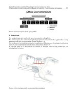
2. Overview of Bionic Cockroach Robots
A cockroach has an effective formation of six legs that accomplish complex movements
regardless of terrain conditions, as shown in Fig. 1. In rapid movement, the front and hind
legs of one side and middle leg of the other side forms a group. As a result, three points
distribution ensures excellent movement stability (Bai et al, 2000).
Fig. 1. Cockroach with six legs spreading out.
Biologists at the University of California at Berkeley have experimented on cockroach’s
adjustment to external disturbances. A very small cannon was fixed to a cockroach. A lateral
thrust with a duration of 10 milliseconds is exerted to the cockroach using recoil of cannon.
Bionic Limb Mechanism and Multi-Sensing Control for Cockroach Robots 87
It was found that this cockroach had adjusted its body balance well before taking the next
new step. It turns out that a cockroach has control balance ability that far exceeds high speed
computer control. So far, researchers struggle to find a satisfactory scientific explanation
about cockroach's such natural ability. Many multidisciplinary difficult issues involved in
the bionics study leads to wild science fascination, and bionic robotics has become an
emerging research subject that deserves in-depth exploration.
In the past bionicst had attempted to develop new fashioned vehicles to achieve agile
motion on rough terrains by studying cockroach locomotion. At the same time, biologists
were intrigued by neural network of cockroach's nervous system which works very
effectively despite its simple structure. In September 2004, The National Science Foundation
(NSF) announced a $5 million, five-year grant to the University of California, Berkeley. The
grant funds biologists, engineers and mathematicians from universities across the country to
try to understand the mechanical and neurological basis of locomotion. This signifies an
important effort in search of in-depth understanding of cockroach locomotion and its
intelligence.
Owing to the special features of cockroach, in recent years robotics academics have devoted
intensive research effort to the development of cockroach robot. Based on the development
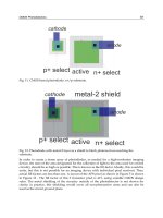
in the past decades, cockroach robots can be roughly categorised into three types. The first
type is “Robot” series, shown in Fig. 2.
Robot I Robot II
Robot III Robot IV
Fig. 2. Robot series of cockroach robots
In this series, the contour design, developed by Case Western Reserve University, has
features of bionic mechanism. Its first generation prototype Robot I is made of six legs of
Mobile Robots - State of the Art in Land, Sea, Air, and Collaborative Missions88
two degrees of freedom (DOF) and driven by Direct Current (DC) motors. It has a bionic
neural network controller. In the second generation prototype Robot II, each leg has 3 DOF.
The robot adopts a distributed control system to achieve coordinated motion of legs and
insect gait. Robot's physical height and orientation are taken charge by a central controller.
In the third generation prototype Robot III, the number of degrees of freedom is distributed
among the six legs unequally. There are a total of 24 DOF, with each of two front legs having
5-DOF, middle leg 4-DOF, and hind leg 3-DOF. Furthermore, pneumatic drives are
employed to obtain a larger explosive force. Such design makes front leg most agile, and the
leg has guiding and sensor function. Middle leg is agile enough to hold up and turn the
robot. Hind leg is least agile, and is provided with a strong propulsive force. (Quinn &
Ritzmann, 1998). The fourth generation prototype Robot IV is based on Robot III, and uses
artificial muscle to approach biologic bionics (Quinn et al, 2003).
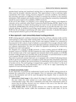
The second type of cockroach robots is represented by Whegs that is also developed by Case
Western Reserve University. The Whegs series of cockroach robots is shown in Fig. 3. The
contour design does not follow cockroach’s bionic mechanism. Instead it takes advantage of
both wheel type movement and leg type movement, then abstracts features of cockroach
movement to carry out mechanism design and function simulation (Schroer et al, 2004;
Quinn et al, 2004). Whegs robot is thus based on abstract biology theory (Allen et al, 2003).
In Whegs I, each leg has only one rotational DOF for wheel type movement. It is built with a
tri-spoke structure which allows for movement on rugged road. Whegs II can bend its body
to have better movement agility than Whegs I. Whegs III's structure has the feature of micro
motion and it has only four tri-spokes instead of six. The terminal of its tri-spoke has barbs
which facilitate wall climbing and moving on rugged road. Whegs IV is similar to Whegs II,
but it does not have flexible joint as in Whegs II. Its main improvement is that its tri-spoke
structure has flexibility and compliance, which benefits transversal motion.
Whegs I Whegs II
Whegs III Whegs IV
Fig. 3. Whegs series of cockroach robots
The third type of cockroach robots is RHex, developed by University of Michigan, UC
Berkeley and McGill University. Fig. 4 shows the prototypes developed through different
Bionic Limb Mechanism and Multi-Sensing Control for Cockroach Robots 89
stages of development. RHex is similar to Whegs in that 6-DOF bionic cockroach movement
is achieved based on abstract biology theory (Sarandli et al, 2000). The first generation
prototype Rhex 0.0 was developed in 1999. Then Rhex 0.1 and RHex 0.2 were improvements
on RHex 0.0. The improvement of RHex 0.1 is mainly the mechanism, resulting in a 10%
weight reduction. Rhex 0.2 incorporates tactile sensors to detect surrounding environment
(Moore et al, 2002; Komsuglu et al, 2001). In recent years, controller with gait adaptive
algorithm further enhances function of RHex (Weingarten, 2004).
RHex 0.1 RHex
Fig. 4. RHex series cockroach robot
Case Western Reserve University has further studied cockroach's mechanical structure, and
developed MechaRoach. The robot’s walking and wall climbing functions are built
according to the mode of cockroach's bionic motion (Wei et al, 2004). Fig. 5(b) compares the
leg structure of MechaRoach with a biologic cockroach in different scale factors. Different
from Robot series mechanism bionics, MechaRoach has only one initiative joint in each leg,
and it realizes mechanism bionics through crank rocker (Boggess, 2004). Such motion
function is not as versatile as those in the previous three types of cockroach robots.
(a) MechaRoach (b) Comparison of legs structure
Fig. 5. MechaRoach cockroach robot
Currently the research focus of cockroach robot is mainly on motion agility and smoothness
control. As far as leg mechanism is concerned, bionics research mostly deals with simulation
of cockroach leg structure topology that treats hip joint, knee joint and ankle joint as serial
mechanism. Latest human bionics analysis manifests that human shoulder joint movement
depends on muscular cable-driven to drive joints. Such cable drive is an inter-coupled
parallel mechanism linking shoulder, elbow and wrist.
Mobile Robots - State of the Art in Land, Sea, Air, and Collaborative Missions90
Fig. 6. Sketch of human arm drive
It is found from the structural analysis of cockroach leg that Cockroach motion control is
accomplished by a parallel structure. What impact does a parallel structure have on
cockroach's motion state? Does it help cockroach's stability of motion, load capacity and skip
ability? Does it cause adverse impact on velocity of movement? Discovering these answers
may provide new clues for humans to explore the secret of cockroach motion ability. In this
regard, developing parallel mechanism to emulate cockroach leg has become an important
premise for cockroach motion control.
Conventionally robot links and joints are rigid. But biologic limbs and joints are flexible.
Cockroach leg's flexibility provides spontaneous regulation of movement stability with little
computation in the brain. Hence, constructing cockroach legs with flexible materials to
emulate the bionic functions is indeed a significant step towards bionic legs. So far, there
have been reports about using insulation elastomer man-made muscle driver (Kornblush et
al, 2002). Although flexible material brings benefits to motion stability, it faces some
practical difficulties in motion control.
Cockroach has superior movement adaptability to differtent terrain conditions. Such
mobility is attributable to two bionics aspects: i) cockroach body and legs distribution of
structure, and ii) fast sensor information processing capacity and virtual intelligent control.
In the latter, touch and vision sensing plays an important role in realizing the intelligent
motion control, and hence requires in-depth research. In addition, sensor information
processing empowered by real-time computation and multi-sensor information fusion
allows a cockroach robot to perceive its operational environment responsively and
accurately. These two aspects of sensing and information processing are challenges that
must be overcome to mimic bionic operations of a cockroach.
Although robotic vision has been widely used in a controlled environment, how to make it
adaptable to varying and unknown environments remains to be a challenge. Human visual
system is highly robust, and removes redundant information and extracts useful
information that is related to current visual behavior from profuse visual information. As an
illustration, once fixing their point of attention to an object, eyes follow the moving object so
that the object is imaged in the central fovea (sharp image) all the time. When the object
exceeds the physiologic limit that eyeball can turn, human will resort to head, even body's
turn to follow the object and obtain a clear image as far as possible.
When humans observe a scene, eyes often focus on some characteristic points of the scene.
Fourier spectrums of these characteristic points contain many high frequency components
and amounts of information. If we can control eyes and make eyes fix on the goal of interest,