Mobile Robots book 2011 Part 3 potx
Bạn đang xem bản rút gọn của tài liệu. Xem và tải ngay bản đầy đủ của tài liệu tại đây (6.5 MB, 25 trang )
A Field Robot with Rotated-claw Wheels 41
retracted inside the wheel body (Now the rotated-claw wheel is the same as conventional
circular wheel). It shows that the acceleration varies from -0.13g to 0.13g. Compare Figure 13
with Figure 14, we can see that stability of the rotated-claw wheel under the condition of
retracted claws is similar to that of conventional circular wheel.
Fig. 12. Plumb direction acceleration curve of Rabbit when the rotated-claw wheels make
clockwise rotation on bituminous macadam ground
Fig. 13. Plumb direction acceleration curve of Rabbit when the rotated-claw wheels make
anticlockwise rotation on bituminous macadam ground
Fig. 14. Plumb direction acceleration curve of Rabbit when the rotated-claw wheels rotate
with retracted claws on bituminous macadam ground
It is obvious that the motion stability under anticlockwise rotation is more stable than that
under clockwise rotation. The reason is that the claw can swing into the wheel body under
anticlockwise rotation while the hexagon effect causes the bumpiness under clockwise
rotation. So the Rabbit should be commanded to move in a backward mode (i.e., all the
wheels rotate in anticlockwise direction) on flat hard ground.
Mobile Robots - State of the Art in Land, Sea, Air, and Collaborative Missions42
4.2 Performance of climbing obstacles
4.2.1 Dry soil terrain
In order to test Rabbit’s motion performance on dry soil terrain with multi-obstacle, we did
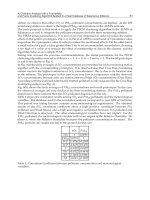
another experiment as shown in Figure 15. Figure 16 shows the acceleration curve of Rabbit
in plumb direction that denotes the acceleration varying from -0.125g to 0.125g. Figure 17
gives the acceleration curve of Rabbit in plumb direction on dry soil when the wheels rotate
in clockwise direction. It shows that the acceleration varies from -0.10g to 0.10g. Figure 18
gives the acceleration curve of Rabbit in plumb direction on dry soil when the Rabbit moves
under the condition of retracted claws, which shows the acceleration varies from -0.10g to
0.10g. Compare Figure 17 with Figure 18, we can see that stability of the wheel is as good as
conventional circular wheel under the condition of retracted claws.
It is obvious that the backward mode is smoother than forward mode (i.e., all the wheels
rotate in clockwise direction) when Rabbit operates on dry soil. But the two results are
approximative. The reason is that the claw can sink into soil and the obstacle-climbing
capability is enhanced. So Rabbit should move in a forward mode when operates on dry soil
terrain with multi-obstacle. The highest obstacle on dry soil terrain that the robot can climb
over is 13cm. The experiments also show that Rabbit can step over the clod or stone whose
dimension is equivalent to the diameter of the wheel.
Fig. 15. Rabbit moves on dry soil terrain
Fig.16. Plumb direction acceleration curve of Rabbit while the robot moves forward on dry
soil terrain
A Field Robot with Rotated-claw Wheels 43
Fig. 17. Plumb direction acceleration curve of Rabbit while the robot moves backward on
dry soil terrain
Fig. 18. Plumb direction acceleration curve of Rabbit while wheels rotates under the
condition of retracting claws on dry soil terrain
4.2.2 Step terrain
When the robot moves on steps terrain, Rabbit should move in a forward mode (i.e., all the
wheels rotate in clockwise direction), because the claw can catch step in front of the wheel
and help the robot to climb over it easily in the forward mode. Table 1 shows the
experimental results in different step height.
Step height/cm 2.2 3.9 6.3 8.1 9.0
Result Success Success Success Success Fail
Table 1. Experimental results on different height step
It is obvious that the rotated-claw wheel can climb over the 8.1cm step that is almost 1.35
times of wheel’s radius as shown in Figure 19. This verifies that the rotated-claw wheel can
improve the obstacle-climbing capacity.
Fig. 19. Climbing step in a forward mode
Mobile Robots - State of the Art in Land, Sea, Air, and Collaborative Missions44
4.2.3 Slope terrain
In order to test Rabbit’s motion performance on slope terrain, we did other experiments as
shown in Figure 20, in which the Rabbit climbs over slope terrain in a forward mode.
Fig. 20. Rabbit climbs over slope terrain in a forward mode
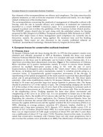
Figure 21 and Figure 22 show the angle curve when Rabbit climbs slope terrain in forward
mode and backward mode respectively. We can see that Rabbit can climb a slope up to 40°
in the forward mode, in contrast, Rabbit is able to climb a slope just up to 31° in backward
mode.
Fig. 21. Angle curve when Rabbit climbs slope terrain in forward mode
Fig. 22. Angle curve when Rabbit climbs slope terrain in backward mode
Comparing Figure 21 and Figure 22, the rotated-claw wheel increases the climbing slop
angle up to 9 degree. The reason is that the claw can sink into soil in motion, which
enhances physical attraction between the wheel and ground. So Rabbit should move in a
forward mode when it moves on slope terrain.
A Field Robot with Rotated-claw Wheels 45
4.2.4 Lunar soil simulation
In order to adapt to the utilization in planetary, we did experiments on simulated terrain of
lunar soil whose material is pozzuolana. The lunar soil is loaded in a trough which has
dimensions of 300cm×80cm×60cm as shown in Figure 23. Void ratio (It is defined as the
ratio of the volume of all the pores in a material to the volume of all the grain) of the lunar
soil is approximately from 0.8 to 1.0, and density of the grain is 2.77g/cm3.
Fig. 23. Trough for lunar soil simulation
We tested Rabbit’s motion performance on rough terrain and multi-obstacle terrain made up
of lunar soil as shown in Figure 24 and Figure 25. The result shows that Rabbit can move
freely on simulated lunar soil.
Fig. 24. Experiment on rough terrain
Mobile Robots - State of the Art in Land, Sea, Air, and Collaborative Missions46
Fig. 25. Experiment on multi-obstacle terrain
In addition, we tested Rabbit’s horizontal pulling capacity on simulated lunar soil in both
forward and backward modes (Figure 26). The experimental results show that Rabbit can
generate maximum pulling forces of 26.5N in forward mode, and 25.1N in backward mode.
Fig. 26. Rabbit’s horizontal pull testing
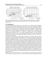
5. Performance comparison
According to the available data from literature, we compare the performance of Rabbit with
MFEX and Spirit robots. MFEX (Microrover Flight Experiment) was a small rover designed
by JPL (Jet Propulsion Laboratory) in 1990s. It was launched to Mars in December 1996 [9].
Spirit is one of the latest Mars rovers designed by JPL. It landed on Mars on January 4, 2004
[10], and finished exploration mission with flying colors in the following years (and still
alive). Table 2 lists the data comparison among Rabbit, MFEX, and Spirit. From the table, we
can see that maximum slope the Rabbit can climb is larger than that of the other two rovers
although Rabbit only equipped with 4 rotated-claw wheels (2 wheels less than the other
rovers). In addition, Rabbit can climb over step which is higher than the radius of wheel.
Robot name Rabbit MFEX Spirit
Mass 10.5Kg 9Kg 176.5Kg
Dimensions 57 cm×43 cm×30.9cm 63 cm×48 cm×28cm 140 cm×120 cm×150cm
Chassis type
Body mounted to
rocker through a
differential
Body mounted to
rocker through a
differential
Body mounted to
rocker through a
differential
A Field Robot with Rotated-claw Wheels 47
Suspension system Springless suspension Springless suspension
Rocker-bogie
suspension
Locomotion system
4 wheels (four
steerable)
6 wheels (outer four
steerable)
6 wheels (outer four
steerable)
Maximum speed 0.153m/s 0.02m/s 0.046m/s
Operational range 1Km 10m 1Km
Layout of wheels
Claw-wheel with
120 mm diameter
60 mm width
wheels with
130 mm diameter
60 mm width
250 mm diameter
Motion control
processors
One 2407A DSP One Intel 80C85
Max. step height
13cm
(Can climb over the
step whose height is
1.35 times higher than
the radius of the
wheel)
Less than 6.5cm Less than 12.5cm
Maximum slope
40 ° in forward mode,
31 ° in back mode (in
soft soil)
32 ° (dry sand)
17 ° (lunar soil
simulant)
16 ° at least
30 ° in the nature of the
Mars soil and terrain
Table 2. Performance comparison of Rabbit, MFEX, and Spirit
6. Conclusion
In this paper, we introduce a field robot using the rotated-claw wheel that has strong
capacity of climbing obstacles. The experimental results demonstrate that Rabbit can move
in different terrain smoothly and climb over step of 8.1cm and slop of 40°. The Rabbit can
adopt different moving modes on different terrains.
(1) Rabbit should move in backward mode on flat hard ground.
(2) Rabbit should move in forward mode on rough, slop, and step terrains.
Because the rotated-claw wheel overcomes the disadvantages of conventional mobile
robot wheels, it provides a better solution for field and planetary robots.
7. Acknowledgment
We thank Wen Li, Gang Sun, and Peng Sun of Beihang University for their valuable help in
the experiments of lunar soil simulation.
8. References
Cuilan Li; Peisun Ma; Xueguan Gao & Zhikui Cao. (2005). A new six-wheel lunar robot for
uneven surface. Drive System Technique, Vol. 19, No. 1, (Mar. 2005) page
numbers(9-13), 1006-8244 (in Chinese)
Alessio Salemo; Svetlana Ostrovskaya & Jorge Angeles. (2002). The Development of
Quasiholonomic Wheeled Robots, Proceedings of the 2002 IEEE international
Conference on Robotics and Automation, Vol.4 , pp. 3514 – 3520, Washington, DC,
May. 2002.
Mobile Robots - State of the Art in Land, Sea, Air, and Collaborative Missions48
Randel A. Lindemann; Donald B. Bickler; Briand. Harrington; Gary M. Ortiz & Christopher
J. Voorhees. (2006). Mars exploration rover mobility development. Robotics &
Automation Magazine, IEEE, Vol. 13, No. 2, (Jun. 2006) page numbers (19-26), 1070-
9932.
Takashi Kubota; Yoji Kuroda; Yasuharu Kunii & Ichiro Nakatani. (2003). Small, light-weight
rover Micro5 for lunar exploration. Acta Astronautica, Vol. 52, No. 2-6, (Jan Mar.
2003) page numbers (447-453), 0094-5765.
Fanghu Liu; Jianping Chen; Peisun Ma & Zhikui Cao. (2002). RESEARCH STATUS AND
DEVELOPMENT TREND TOWARDS PLANETARY EXPLORATION ROBOTS.
Robot, Vol. 24, No. 3, (May. 2002) page numbers (268-275), 1002-0446. (in Chinese)
Zongquan Deng; Haibo Gao; Ming Hu & Shaochun Wang. (2003). Design of lunar rover
with planetary wheel for surmount obstacle. Journal of Harbin Institute of Technology,
Vol. 35, No. 2, (Feb. 2003) page numbers (203-213), 0367-6234. (in Chinese)
Zongquan Deng; Haibo Gao; Shaochun Wang & Ming Hu. (2004). Analysis of climbing
obstacle capability of lunar rover with planetary wheel. Journal of Beijing University
of Aeronautics and Astronautics, Vol. 30, No. 13, (Mar. 2004) page numbers (197-201),
1001-5965. (in Chinese)
Ronggang Yue; Shaoping Wang; Zongxia Jiao & Rongjie Kang. (2007). Design and
performance simulation of a new type wheel with claws. Journal of Beijing
University of Aeronautics and Astronautics, Vol. 33, No. 12, (Dec. 2007) page numbers
(1408-1411), 1001-5965. (in Chinese)
K. Schilling & C. Jungius. Mobile robots for planetary exploration. (1996). Control
Engineering Practice, Vol. 4, No. 4, (Apr. 1996) page numbers (513–524), 0967-0661.
(in Chinese)
Glenn Reeves & Tracy Neilson. (2005). The Mars Rover Spirit FLASH Anomaly. Aerospace
Conference, 2005 IEEE, pp. 4186-4199, Mar. 2005.
3
Mobile Wheeled Robot with Step Climbing
Capabilities
Gary Boucher, Luz Maria Sanchez
Louisiana State University, Department of Chemistry-Physics
Shreveport LA, USA
1. Introduction
The field of robotics continues to advance towards the ultimate goal of achieving fully
autonomous machines to supplement and/or expand human-performed tasks. These tasks
range from robotic manipulators that replace the repetitious and less precise movements of
humans in factories and special operations to complex tasks which are too difficult or
dangerous for humans. Thus an important and ever-evolving area is that of mobile robots.
Extensive research has been done in the area of stair-climbing for mobile robotics platforms.
Humanoid, wheeled, and tracked robots have all been made to climb stairs, however in
most of these cases robots where designed for two dimensional operations and then later
utilized or modified for stair climbing. (Herbert, 2008) Although strides have been made
into exotic forms of legged robots, the conventional methods, such as wheels or tracks still
form the basis for robotic locomotion.
The wheeled mobile systems are useful for practical application compared with the legged
systems because of the simplicity of the mechanisms and control systems and efficiency in
energy consumption (Masayoshi Wada 2006). To better understand the problems faced by
mobile ground based robots one must understand the expected terrain that the machine
must negotiate. This can range from un-level ground to rocky and irregular terrain and in
some cases man-made obstacles such as steps or stairs must be climbed. Each of these
applications has unique challenges and solutions.
In 2003, Louisiana State University-Shreveport took on the task to create an alternate
approach to a rugged terrain robot capable of traversing not only rough terrain, but also
man-made obstacles, such as steps and stairs, with the intent to meet the requirement to
ascend and descend between levels in a building as in the case of security robots performing
their tasks. The project further addressed the issue of observation capabilities to handle
obstacles in the robot’s path.
In conjunction with our Computer Science CSC 410 course in robotics, the LSUS Department
of Chemistry-Physics took up the challenge to develop a robotic design that would meet
these requirements. The criteria that factored into the initial concept phase of the project
were the following: First the robot must be robust, capable of extended service in rugged
environments and carry its own power source. Secondly, the robot must also have versatile
vision systems which can relay the video information back to the operator via radio signals
Mobile Robots - State of the Art in Land, Sea, Air, and Collaborative Missions50
or a fibre optic link. Thirdly, the device should have the ability to climb steps and stairs for
changing floors in a building. The challenge was then handed to the students
A robot using more than four wheels could compete with some tracked devices if the
wheels are driven simultaneously. One approach considered to meet this requirement was
through the use of a hydraulic motor on each wheel. This would allow all wheels to derive
their rotation from one single power source. A central hydraulic pump generating a
constant flow of fluid could provide the source to power the device. This concept was first
patented by Joseph Joy in 1946 (Joy, 1946). Joy described a 16 wheel automobile capable of
being driven by 8 hydraulic motors powered by a single engine and hydraulic pump.
Such a scheme for driving a robot would require two hydraulic pumps and two sets of
motors, one set for the left and one for the right side of the robot. The differential drive
would then allow turning much the same way as tank treads. The motors could be in series
on each side and therefore produce the same rotation for the volume of fluid pumped.
Hydraulic pumps and motors were ruled out in the LSUS robot due to cost and the shear
bulk of two hydraulic systems with proportional rate of flow control.
The concept of wheel sets that can rotate is also not new. As far back as 1932 Raphael
Porcello patented their use in numerous mobile devices from baby carriages to landing gear
for airplanes (Porcello, 1932). Although not driven, these wheel sets demonstrated the
versatility of allowing wheels to be grouped together and have their individual axels fixed
at a certain common radius from the axes of wheel set rotation.
The LSUS design consensus centered on using sets of two wheels that used parallel
individual axels each offset a given radius from the wheel set axis of rotation. In this way,
the wheels could revolve and also be powered from a source of angular speed and torque.
The wheels sets could also revolve in any direction independent of the rotation of the
wheels. This design seemed to satisfy the primary requirements for the robot for both
rough terrain and stair climbing.
2. Related Work
In 1991 King et al patented a method of stair climbing using a robot with rotating wheel sets
(King et al, 1991). This device used two sets of two wheels each for stepping and used a
larger front wheel to ride up and over oncoming steps. This larger wheel was forced by the
rotating rear wheel sets. This novel approach used counter rotation between the rear wheel
sets and the individual wheels in the sets. Thus, if properly geared, each wheel set would
“step” motionless on each stair step without rotating relative to the stairs. This requires the
proper ratio of wheel set speed and rotational speed for the tires.
The early work by King et al was followed by several unique approaches to rotating wheel
sets for stair climbing robots. Andrew Poulter set forth the concept of a robotic all-terrain
device that consisted of two elliptical halves or “clam shells” that supported the drive
mechanism for two wheels (Poulter, 2006). These clam shells were articulated as connected
together with a common shaft. In this way, the robot could almost continuously have all
four wheels in touch with the surface. Although not intended for stair climbing this device
demonstrated articulated wheel sets.
Poulter also used a long boom situated between the two clam shells that could be rotated to
right the vehicle should it topple over or need to raise the forward or rear wheel sets. This
Mobile Wheeled Robot with Step Climbing Capabilities 51
device also incorporated the concept of having no front or rear, handling either direction
desired as forward.
In 1998 Yasuhiko Eguchi from Heyagawa, Japan was issued a patent on a system of eight
wheels driven in sets of two wheels each (Eguchi, 1998). This system could both rotate
wheel sets and drive the wheels individually and separately. This vehicle had its individual
wheel drive and wheel set drive linked using gears. As the wheel sets were driven, the
gears would transfer torque to the individual wheels. Having the power transferred in this
way caused the wheel sets to rotate opposite to the wheels, much the same as King et al.
The LSUS robot design paralleled the Eguchi concept set forth in his 1998 patent. As far as
the authors are concerned, the LSUS design is the first prototype of its kind that applies the
Eguchi concept and combines stair climbing with rough terrain negotiation capabilities. The
LSUS adaptation of this wheel set concept for robotics limited the rotation of the wheel sets
to approximately 35 degrees in either direction from level using pneumatic cylinders affixed
to each of the wheel sets. The type of pneumatic control valves allowed a step up or down
of the wheel sets and also a “neutral” position where the air valves allow full and free
motion as will be discussed later in this chapter. Also, the use of chain drive rather than
gears was incorporated in the LSUS robot. This less expensive alternative to gears requires
lower maintenance and is easily replaced should failure occur. Other works that apply the
Eguchi concept for stair climbing is that of Minoru et al, 1995 although with Figure 1 shows
WHEELMA (Wheeled Hybrid Electronically Engineered Linear Motion Apparatus), the
LSUS designed robot that uses the Eguchi concept.
Fig. 1. Wheelma Robot based on Eguchi system
Mobile Robots - State of the Art in Land, Sea, Air, and Collaborative Missions52
Extreme examples of wheeled robots use multiple wheel drive that is articulated not in a
rotary manner but in a vertical manner. A vertically wheel articulated system is seen in a
design by the Intelligent Robotics Research Centre in Clayton Victoria Australia (Jarvis,
1997). This robot, the size of a small car, uses six wheels that can move vertically to
negotiate rough terrain. This robot was inspired by a Russian model of a Marsokhod Mars
Rover M96. This robot was been located at the Intelligent Robotics Research Centre at
Monash University since 1997.
Another unique example of articulated wheeled robots is the Octopus developed by the
Swiss Federal Institute of Technology Zurich (Lauria et al, 2002). This wheeled design uses
tactile sensing in each wheel to identify and negotiate obstacles. This robot’s
instrumentation can identify the height of obstacles and the system can decide how to
handle the obstacle such as total avoidance or decide a strategy to overcome the obstacle.
This eight-wheeled robot is small and can be configured to a variety of wheel
configurations.
3. WHEELMA
A priority of the LSUS design was for it to be articulated so as to conform to un-level terrain
as needed and continue to drive the robot in forward and reverse directions. Articulation
requires a method of suspension with a certain amount of slack for the wheels to adjust to
varying contours as they roll over terrain. Articulation combined with all-wheel drive has
been used to handle rough terrain negotiation.
Fig. 2. Wheelma Resting on Eight Wheels
Mobile Wheeled Robot with Step Climbing Capabilities 53
WHEELMA uses soft rubber inflatable wheels. All eight wheels of the robot use economical
10-inch tires and hubs that rotate around a unique hub design attached to a rigid frame.
Figure 2 shows WHEELMA with both wheel sets level as would be the case typically on a
flat floored surface. Four internal motors effectively drive the wheels sets in both forward
and reverse directions through appropriate speed reduction. The wheel-set rotation around
a central axel delivers the articulation needed to conform to terrain contour. Figure 3(a) and
3(b) show the side and top profile of the wheel sets used on WHEELMA.
a)
b)
Fig. 3.(a) Side View of Wheel Set (b) Top View of Wheel Set
Mobile Robots - State of the Art in Land, Sea, Air, and Collaborative Missions54
This design further allows fulfillment of the above stated design criterion with the use of a
simple left-right differential control system, similar to the classic arcade game “Tank.” Each
control device or lever controls one side of the robot. The left control drives the two left
wheel sets, while the right control drives the right side wheel sets. This allows forward and
reverse motion and also rotation around an axis central to the robot in a fashion similar to a
tracked vehicle.
Each wheel set has two wheel axels that are attached to a cross bar. Figure 3(b) shows the
crossbar. The 1.25-inch axel that passes through two ball bearings (not shown) held in place
by the robot’s frame allows full articulation of the wheel sets. Inside each of these 1.25-inch
axels is set of two needle bearings that support a second 0.5-inch axel used for driving the
two wheels. Thus, an axel inside an axel enables rotation and horizontal translation for the
wheel-sets. To allow for the tank-like operation of the robot, all wheel sets are allowed to
“float” at times creating a contour following approach similar to a treaded vehicle. The
wheel-sets also must encompass a control mode where they can both be locked or driven.
With each wheel set in either of these two modes, it must be driven through the central
drive shaft for locomotion of the robot. The initial approach utilized in WHEELMA used
electric clutches that allowed floating operation where the terrain requires such and locked
rotation where needed for confronting obstacles. The clutches would be activated to thus be
driven by a high torque source to rotate each wheel-set. This approach could deliver stair
climbing capabilities.
Full rotational capabilities for each wheel set would demand a method of monitoring the
position of each wheel-set. This task could be accomplished by means of an optical encoder.
The optical encoder would digitally measure the angle of rotation for each wheel set shaft.
As the shaft moves, digital pulses would be counted and at any given time the counter
could be read to determine the position of the encoder and thus the position of the wheel-
sets for this application.
This method of sensing would require an index mark where the electronics used for
counting rotation pulses could find the level position and zero the counters that measured
angular displacement. Otherwise, the encoder and digital circuit would not know when the
sets were level. The clutch based system posed one daunting problem, in case of a power
failure the clutches would disengage. If this occurred while the robot was climbing stairs
the clutches would in turn release the wheel-sets causing a catastrophic loss of control. An
alternate approach to the electric clutches was devised.
The new approach would limit the wheel set movement to approximately 35 degrees
clockwise and counterclockwise. Although agility would be compromised, this approach
would allow upward rotation for oncoming obstacles such as curbs and steps as well as
rotation in the opposite direction for possible clearing of the robot from stuck positions.
While continuous rotation may have been more beneficial to certain climbing operations the
simpler approach was found to be more adequate for most operations.
A method to lower and raise each set of wheels was the next step in the design. The chosen
approach replaces the clutches and drive mechanisms with four 2-inch diameter bore
pneumatic cylinders each with its own air control valve operated electrically. This system
solves two issues. It provides the wheel sets rotation and also afforded a method of
achieving the “float” condition, which allows the wheel-set’s unhampered movement as the
robot negotiates terrain.
Mobile Wheeled Robot with Step Climbing Capabilities 55
The float condition is achieved with the use of pneumatic control valves that have an off or
neutral position which allows for the exhausting of both ports of the double acting cylinders
to the outside air. Thus, when the wheel-sets rotate in one direction outside air is drawn
into one double acting cylinder on one end and exhausted from the other. The use of
exhaust filters addressed the resulting drawback of dirty air entering the system that could
cause a buildup of debris in the air valves and cylinders.
Electronic control for each wheel-set is initiated by the ground based control unit and once
this control information reaches the robot, power Darlington transistors control the current
to actuate the pneumatic control valves. This separate control over each wheel-set was
found to have great utility in ways not initially conceived.
This independent wheel-set control further facilitates the turning of the robot on surfaces
that afforded a high coefficient of friction between the robot wheels and the surface. This
was first noted on concrete where the coefficient of friction can be as high as 1. Turning
with all eight wheels in the floating position requires a great deal of wheel torque due to the
extended front and back wheels having to slide laterally to some extent due to the general
nature of all differentially operated locomotion systems.
Since the vehicle can lift the outer ends of its tracks, or outer wheels in the case of
WHEELMA, the device can turn on the inner portions of the tracks or the four inner wheels.
This fact proved invaluable for turning with lower levels of power especially when the robot
had been working and the batteries were supplying lower voltage and the electronics and
motors were reaching higher temperatures all of which reduce the drive torque.
Raising the outer wheels places the same weight loading totally on the inner wheels
maintaining approximately the same amount of friction between the surface and drive
system. Much of the turning friction is reduced by the shortened moment arms of the inner
wheels which allow for much lower resistance when turning since the resulting wheel drag
will be decreased. Effectively shortening the length of the robot allows for far less lateral or
non-rotational component yielding a greater turning ability.
The control portion of WHEELMA consists of a custom built base station which provides
switches for defining options on the robot along with the standard two levers for the
differential driving of the device in forward and reverse directions much the same as a tank.
Figure 5 shows the base station along with associated switches, receiver controls, and TV for
monitoring returning video from the robot.
Mobile Robots - State of the Art in Land, Sea, Air, and Collaborative Missions56
Fig. 4. Wheelma Resting on Inner Wheels
Fig. 5. Controls Station
Mobile Wheeled Robot with Step Climbing Capabilities 57
4. Vision System and Directional Orientation
Many robotic designs rely on either physically turning the robot around 180 degrees to exit
tight situations or else attempt to back out of restrictive spaces the same way they were
entered. Many robots have the ability to reverse their viewing direction either by rotation of
the camera or by using a secondary camera mounted to look aft.
It is also difficult to convey to an observer the lack of depth perception that occurs while
using only one robotic camera at a time. Although two cameras could afford a stereo view
of the operating area to the operator wearing a head-mounted viewing device, the difficulty
in transmitting two simultaneous video signals precludes this practice for more
applications. Such transmissions are often plagued by the need for excess transmission
bandwidth for transmission or inter-modulation between two closely spaced video
transmitters operating at nearly the same carrier frequency.
Using one camera for forward and one for reverse makes driving the robot easier in close
quarters as the operator can always be looking in the direction of travel. This approach can,
in some cases, eliminate having to perform a 180 degree turn by simply switching cameras
and backing out of a given situation. Reversing the view however does not in itself reverse
the control action necessary to drive the robot. This fact makes the operation extremely
disorienting to the operator. Also the drive characteristics of the robot may change for
certain robots used in the reverse mode of travel.
Because WHEELMA is basically symmetrical with no difference in handling characteristics
in forward or reverse, the ability to reverse the robot’s direction of control was incorporated.
The video circuit has provisions for up to eight cameras multiplexed through a specially
designed video multiplexer controlled by the base station. This multiplexer feeds a single
video output from one camera at any given time to the video transmitter on the robot. This
allows for easy installation of two cameras, one at each end of the robot. Figure 6 shows the
video multiplexer.
This multiplexer board uses two DG540DN video multiplexers which are under the control
of the robot logic. This video multiplexer has the feature of using two analog CMOS
switches in series to pass the video signal. When the channel is not selected the switches
both go to the open mode and a third switch grounds the connection between the two. This
lowers crosstalk to a minimum. Although there are eight possible connections to this
multiplexer, only two are used for WHEELMA’s cameras. Refer to Figure 1 and 2 for a view
of the cameras used. These cameras in the figures are in small square enclosures. Each
looks toward its respective end of the robot.
Mobile Robots - State of the Art in Land, Sea, Air, and Collaborative Missions58
Fig. 6. Video Multiplexer
Fig. 7. DPDT Relay
Using a reversing strategy allows the operator to literally switch ends with the robot with
the change of a single toggle switch at the base station. This toggle will switch the cameras,
the left and right controllers, and even the lighting on the robot. In this way if WHEELMA
enters a room and the remote operator desires to exit the room, one flip of a switch causes
the view to change along with all necessary controls and lighting to simply drive out. Thus,
WHEELMA has no front-back orientation and relies solely on the remote operator’s
manipulation of the direction switch.
Figure 7 shows the simple strategy for accomplishing a total reversal. A DPDT relay is
shown that is driven by an SPST reversing switch. Lighting control is not shown, but can be
added with using the microprocessor’s logic located in the base station. Note that power is
DC voltage and is supplied to two potentiometers connected to the left and right drive
control levers (tank controls). When the relay is activated the polarity of the signal going to
the two pots is reversed thus changing the directional nature of the controls Secondarily the
Mobile Wheeled Robot with Step Climbing Capabilities 59
left-right input from the pots are also switched to compensate for the left-right reversal
effect. One switch can thus control a total reversal of control operation.
It should not be construed that the robot cannot reverse and back out of a tight location
maintaining the same front-back orientation that carried the device into the room. The robot
can also switch cameras and back out without reversal. However, using this system is
seamless in operation and solves many problems encountered with some robots.
When setting up such a reversing control system, once should endeavor to place the zero
thrust position in the exact vertical center position of the levers. Thus, when the left and
right control levers are centered there is no thrust to the robot wheels. This is extremely
important when doing a reversal as any residual thrust at the time of reversal will become
an opposite thrust upon reversal. Several times WHEELMA operators have become
disoriented through a combination of slight forward or reverse thrust set by the levers at the
time of reversal.
It would be good design practice to either not allow reversal with thrust applied or to have a
centering method to be assured that no residual thrust is present in the control lever settings
when a reversal is undertaken. Allowing a spring loaded return to center for the thrust
levers along with an indicator for denoting zero thrust could be used to prevent this effect.
5. Control Link
A simple system using the 1.25-meter amateur radio band was used to transmit all of the
control signals from the base station to WHEELMA. This band of frequencies available to
all amateur radio operators for sending ASCII packets was used in this and other previous
robotic designs. (CGS Network)
The motor control information begins at the two-lever input for the tank-like control of the
robot. These two levers are attached to two high quality potentiometers that divide the
applied 5-volt potential. With each lever in the center position (vertical) the voltage is
measured as 2.5 volts. As the levers are moved forward and backward the voltages rise and
fall above and below this 2.5-volt center value.
The voltages are conditioned via an operational amplifier interface before being presented
to a Motorola MC68HC711 microcontroller where the 8-bit A to D converters sample the
voltage levels. Each voltage level is then converted into a 2’s compliment signed number
that is transmitted to the robot’s receiver. A continuous stream of these sampled lever
voltages are sent using ASCII transmission techniques. Each complete motor control sample
is sent as one line of ASCII text followed with Return and Line Feed characters.
Each text string transmitted contains a starting character. A colon (:) was chosen to begin
each string. Following the colon two ASCII bytes are transmitted representing the 2’s
compliment signed motor control sample position of the left lever for the left motor sets.
Then the right motor set sample is sent using another two ASCII characters. At this point in
the stream a simple checksum is transmitted followed by a Return and Line Feed. These
two control characters in ASCII have provided a good way of showing all control
information using a simple computer terminal for debugging purposes.
This stream of serial information at 2400 baud is sent to a modulator where it is converted to
a standard FSK audio signal. This signal is then transferred to an amateur FM modulated
transmitter operating on the 1.25-meter band. This 1-watt unit is the legal limit for amateur
Mobile Robots - State of the Art in Land, Sea, Air, and Collaborative Missions60
band transmissions for radio control purposes as authorized by the FCC. An Omni-
directional whip antenna radiates the signal and has a range of over one mile line of sight.
Reception is done with a 1.25-meter crystal controlled receiver feeding a demodulator. The
resulting 2400 baud serial stream is then sent to a second MC68HC711 microcontroller
through the Serial Communications Interface (SCI) where the values are parsed and the
checksum calculated and compared against the embedded checksum. If the checksum and
framing characters match what is expected, the string is passed to a motor controller circuit
via two parallel cables, one for each channel (Left and right).
A duty-cycle type motor control is utilized. This is implemented in WHEELMA using a
specially designed duty-cycle board that takes parallel information in from the
microcontrollers and converts it to controlled rectangular waveforms that drive the motor
controllers. The motors are controlled using power MOSFET circuits, one for each of the
four motors that drive the four wheel sets.
5. Voice System
To complete the work started by our computer science group that initiated the design of
WHEELMA, it was decided to give the robot a voice. For this capability, the RC Systems
DoubleTalk© RC8650 integrated circuit chip set was used. This set comes complete on a
small module called the V-Stamp and is interfaceable to a standard microcontroller [8]. For
this we chose the same Motorola MC68HC711 microcontroller used for other functions and
interfaced it with the V-Stamp using the SCI port on the microcontroller.
Figure 8 shows the voice system consisting of two circuit boards (PCBs). The top board
shows a standard microcontroller board connected to a board housing the V-Stamp. The V-
Stamp board has a Maxim RS-232 driver IC for connection of the device to both the outside
programming computer and also the microcontroller.
The V-Stamp uses a 3.3 volt power supply and has a 0 to 3.3V serial connection that is
relatively easy to connect to any standard microcontroller. The V-Stamp operates in several
modes. First, you can operate this device in the text-to-speech mode where the
microcontroller can simply send text to the device and it will speak it with a number of
different voices that are software selectable. Secondarily, you can record up to 33 minutes of
sound into the RC86L60F4I version of the V-Stamp and play it back on defined boundaries.
The user can use Indexes or Tags which allow the user to utilize either ASCII text labels or
serial numbers for each word or phrase recorded.
In designing the voice system provisions were made to connect an RS-232 cable directly to
the V-Stamp for entering both, the recorded words and messages as well as the tag
information. Software is provided by RC Systems to upload converted .wav type files for
the unit. The process is straightforward and can be mastered in short order.
Provisions were made to send tags for the V-Stamp via the same serial connection from the
base unit. This technique worked well, but requires a separate computer to handle the voice
tags. It was found that voice is extremely difficult to coordinate with robot motions for one
single operator. This additional unit for generation of voice proved valuable during
demonstrations of WHEELMA at locations such as schools and science museums.
Mobile Wheeled Robot with Step Climbing Capabilities 61
6. Future Work
One preferred embodiment of a WHEELMA-type robot would be to return to the 360 degree
wheel set rotation concept of Eguchi but replace the two-wheel sets with three-wheel sets.
The three wheel sets would rotate into position easier in the process of climbing stairs and
should have extremely good functionality in the negotiation of rough terrain. This should
prove highly effective as the wheels sets can rotate for propulsion as well as being driven in
the conventional manner. Similar devices have been developed for carrying heavy loads up
stairs using a three-wheel drive mechanism.
7. References
Sam D. Herbert, Andrew Drenner, and Nikolaos Papanikolopoulos “Loper: A
Quadruped-Hybrid Stair Climbing Robot” 2008 IEEE International Conference on Robotics
and Automation Pasadena, CA, USA, May 19-23, 2008
Masayoshi Wada “Studies on 4WD Mobile Robots Climbing Up a Step” Proceedings of the
2006 IEEE International Conference on Robotics and Biomimetics December 17 - 20,
2006, Kunming, China
Joseph Joy. “Automotive Vehicle” Patent 2393324 Application September 18,1982, Serial No.
458,886 I1 Claims. (a.18 0-17)
Raphael Porcello “Wheeled Device” Patent 1887427 April 6, 1932
Edward G. King, Baltimore; H. Shackelord, Jr., Finksburg; Leo M. Kahl, Baltimore, all of Md.
Patent 4993912 February 19,1991.
Andrew R. Poulter 80128 United States “Rugged Terrain Robot”Patent (10) Patent NO.: US
7,011,171-BI Poulter (45) Mar. 14,2006
Yasuhiko Eguchi “Stairway Ascending/Descending Vehicle Having an Arm Member with a
Torque Transmitting Configuration” Patent 5833248 Nov 10,1998.
Ray A. Jarvis, “Autonomous Navigation of a Martian Rover in Very Rough Terrain” Proc.
International Symposum on Experimental Robotics, March 26-28 1999, Sydney
University, pp.225-234
Lauria, Piguet and Siegwart, R “Octopus – An Autonomous Wheeled Climbing Robot”
Proceedings of the Fifth International Conference on Climbing and Walking
Robots, 2002.
CSG Network (2008). /> :accessed Aug 2008
Mobile Robots - State of the Art in Land, Sea, Air, and Collaborative Missions62
4
Cable-Climbing Robots for
Power Transmission Lines Inspection
Mostafa Nayyerloo, XiaoQi Chen, Wenhui Wang, and J Geoffrey Chase
Mechanical Engineering Department, University of Canterbury
Private Bag 4800, Christchurch 8140, New Zealand
1. Introduction
Power transmission line inspection is of utmost importance for power companies towards
having sustainable electricity supply to vast number of customers in major industries as
well as households in a city. Inspection provides valuable data from status of the line, thus
helps line engineers to plan for necessary repair or replacement works before any major
damages which may result in outage.
Constant energy supply to the customers requires performing all the inspection tasks
without de-energizing the line, so live line inspection methods are of the most interest to
power companies. These companies perform patrol inspection mainly using helicopters
equipped with infrared and corona cameras to detect observable physical damages as well
as some internal deterioration to the line and line equipment. However, aerial inspection is
costly and always there is a risk of contact with live lines and loss of life. Moreover, there are
some critical specifications of the line such as internal corrosion of steel reinforced
aluminium conductors that should be inspected precisely from close distances to the line
that are not accessible by a mobile platform such as a helicopter or even an unmanned aerial
vehicle (UAV). Hence, power companies have endeavored to make especial cable-climbing
robots to accomplish inspection tasks from close distances to the hot line.
Thanks to technological advances, utilizing robots as reliable substitutes for human beings
in hazardous environments such as live lines has become possible. For many tasks requiring
high precision over a long period of time, robots even do their job better than human
operators. However, power companies have mainly focused on automating inspection tasks
more willingly than making autonomous systems to perform repair works on the live line
due to the fact that repair works are often complex to be accomplished by a robot.
In the past two decades, researchers have endeavored to make fully autonomous and
intelligent cable-climbing robots equipped with necessary sensors for hot line inspection,
aiming at making a cable-climbing mechanism with obstacle avoidance capability to pass
the line equipment and the tower. Also some research has been done to devise a durable
power supply method for the hot line inspection robots to make them sufficiently durable to
perform inspection over long distances of live lines without interruptions for recharging the
power source. Inspection data quality enhancement has been another challenging issue in
this field due to the fact that swinging of the inspection robot in windy climates and even
Mobile Robots - State of the Art in Land, Sea, Air, and Collaborative Missions64
sometimes during the navigation makes the captured images of the line, as the main
inspection data for line status evaluation, blurry. These undesirable vibrations also make
some problems in the robot’s navigation, which mainly relies on a vision system, in most of
the proposed designs.
The robot’s mechanical mechanism as main part of the robot design may significantly affect
other issues in the whole design process such as energy consumption and inspection data
quality. Hence, this chapter aims to review some of the main efforts made over the past 20
years in cable-climbing mechanism design for power lines inspection to provide a basis for
future designs and developments in this field.
The chapter has organized as follows. Section two of the chapter briefly reviews different
kinds of faults, which may occur in power lines, and origins of these faults. In the third
section, which is the main part of this chapter, the focus will be on reviewing different types
of mechanisms proposed for navigation and obstacle avoidance on power lines, advantages
and disadvantages of each proposed mechanism over others, and adaptability of these
mechanisms to power line environment. We then conclude the chapter in the last section.
2. Problems of deterioration in transmission lines and their symptoms
Transmission lines are exposed to variety of factors, such as corrosion and wind induced
vibrations, which cause different problems and limit life time of the lines. Damage to the
transmission lines can be categorized into two main groups: damage to the insulators and
damage to the conductors.
2.1 Damage to the insulators
The insulators are affected by impact, weathering, cyclic mechanical and thermal loading,
electro-thermal causes, flexure and torsion, ionic motion, cement growth, and corrosion
(Aggarwal et al., 2000). Temperature difference between hot sunny days and freezing cold
nights as well as the heat generated by fault current arcs cause thermal cycling, which
produce micro-cracks and allows water to penetrate into material. The amount of imposed
stress depends on relative expansibility of dielectric, metal fittings, and the cement used to
fix the metal fittings of the line to the dielectric.
Cement growth, which is mainly caused by delayed hydration of periclase (MgO) as well as
sulphate related expansion, generates radial cracks in the porcelain insulators’ shell and
makes them faulty (Aggarwal et al., 2000). Contaminants in the atmosphere, such as sea or
road salts, can attack both Portland cement itself, or if penetrate into metal parts, can
corrode galvanizing surface. Ionic motion caused by electric field makes this situation
worse.
2.2 Damage to the conductors
The steel reinforced aluminium conductors (ACSR) are one of the most popular conductor
types. The most important phenomenon that degrades such conductors is corrosion of
aluminium strands. Pollutants and moisture, in the form of aqueous solutions containing
chloride ions, ingress into the interface between the steel and the aluminium strands and
attack galvanizing protection of the steel. Corrosion of the galvanizing coat exposes steel
and aluminium to each other and leads to galvanic corrosion between iron and aluminium.
Cable-Climbing Robots for Power Transmission Lines Inspection 65
As an anode, aluminium corrodes rapidly and white powder aluminium hydroxide is
produced. Loss of aluminium strands decreases current carrying capacity and mechanical
strength of the line (Cormon Ltd, 1998; Aggarwal et al., 2000).
In addition to corrosion, wind induced vibrations can make severe mechanical damage to
the conductors due to generating cyclic mechanical load. The wind flow creates vortices
downstream when it passes the line. These vortices produce fluctuating lift and drag forces
causing aeolian vibrations with frequencies from 10-30 Hz and amplitudes of the order of
diameter of the conductor. In bundled conductors, the wind also induces sub-conductor
oscillations, which can cause fretting of the aluminium strands near the clamps. The fretting
reduces the fatigue strength of the line and speeds up the failure process.
2.3 Symptoms of the transmission line damage and detection methods
Damage to the line can be detected through investigation of their symptoms. Most of the
line problems produce unusual partial discharges. Whenever the electric field intensity on
the line surface exceeds the breakdown strength of air, electrons in the air around the
conductor ionize the gas molecules and partial discharges, namely corona effects, occur.
High frequency partial discharges produce radio noise in ultra-high frequency range, as
well as audible noise in ultra-sonic range. In addition to noise, discharges send a current to
the line. This current can also be used to detect faults. Depending on the weather, age of the
line, problem conditions, and other factors, the level of discharge can also be different.
Abnormal temperature is another symptom, which can be used to identify defects on the
transmission lines.
Based on aforementioned major symptoms, following techniques are mainly used for
detecting faults in the transmission lines (Aggarwal et al., 2000):
1. Ultrasonic detection
2. Measurement of corona pulse current inconsistency
3. Partial discharge detector
4. Infrared inspection of overhead transmission lines
5. Radio noise detection system
6. Solar-blind power line inspection system (through detecting UV)
7. Corona current monitor for high voltage power lines
8. Fiber optic application to transmission line inspection
9. Audible noise meters
10. Field testing of insulators
3. Cable-Climbing mechanisms for power line inspection
3.1 The design environment
Power lines are a dangerous environment with intensive electric and magnetic fields. Power
lines are also a complex environment, and difficult for robots to navigate. The simplest
power lines have one conductor per phase hung on insulator strings, which can be either
suspension or strain insulators. Besides insulators, there are other obstacles on the
conductors, such as dampers, aircraft warning lights, and clamps. In bundle power lines,