Mobile Robots book 2011 Part 2 ppsx
Bạn đang xem bản rút gọn của tài liệu. Xem và tải ngay bản đầy đủ của tài liệu tại đây (2.15 MB, 25 trang )
Mobile Robots - State of the Art in Land, Sea, Air, and Collaborative Missions16
systems found in nature to the study and design of engineering systems and modern
technology. The exceptional natural abilities in many animals and insects have drawn much
attention from biorobotists. A common approach is to build animal-like features into robots,
and such robots are called biomimentic robots or simply biorobots.
It is debateable whether biologically inspired robotics should be simply emulation of some
general feature like legs or wings of an animal, or a more considered approach in which
specific structural or functional elements of particular animals is emulated in hardware or
software (Delcomyn, 2007). It is difficult to draw a line between the two, although the latter
may rely on biological aspect more.
The intensive research effort in searching for hardware and software solutions to emulate
specific features of a real animal would expose their efficiency and deficiency, and improve
our understanding of those animal features and engineering capabilities and limitations.
Whether a design solution comes from engineering or a biological perspective, it is generally
agreed that certain degree of fusion and integration between engineering and biology takes
place. Despite minute differences in interpretation and emphasis, bionics, biorobotics,
biomimetics, or biologically inspired robotics is emerging as a discipline in its own right. It
has witnessed an explosion of research interests and efforts in the past few decades
worldwide. Researchers working in this field rightfully claim their own identity –
biorobotists, or bionicists. It is fitting to recognise that engineers apply biological principles
to construct robots, and biorobotics in turn can advance biologists’ knowledge and
understanding of those same biological principles
Rapidly growing interests in biorobotics were confirmed by the statistics shown in
(Delcomyn, 2007). There are more than 1.5 million hits one obtained by conducting a Google
search on the phrase “walking robot”. In terms of research literature included in the ISI Web
of Knowledge database, the number of papers on mobile robotic machines with biological
inspiration or variants as a key phrase has increased from an average of 9.2 papers per year
between 2000 and 2004, to 16 in 2005 (an increase of over 70%), and 30 in 2006 (another
increment of more than 85%). Though not large, this is nevertheless a field that is attracting
much attention.
Biorobotics research has covered many types of animals to be emulated - fish and eel
underwater; dog, cockroach, gecko on land; and black flies, wasps, bumblebees and other
flying insects in air. These robots are built to swim, walk, climb a wall or a cable, or fly.
Wall climbing robots have been considered to replace human beings to perform dangerous
operations on vertical surfaces like cleaning high-rise buildings, inspecting bridges and
structures, or carrying out welding on a tank. The locomotion of a wall climbing robot has
become a key research, which is achieved through some kind of attachment mechanism.
Generally speaking, three main types of attachment mechanisms are used: suction, magnetic
and dry adhesion mechanisms. The suction method creates vacuum inside cups through
vacuum a pump, the cups are pressed against the wall or ceiling so that adhesion force is
generated between the cups and the surface. This effect is dependent on a smooth
impermeable surface to create enough force to hold the robot.
A wall-climbing robot with a single suction cup has been studied in (Zhao et al., 2004). It
consists of three parts: a vacuum pump, a sealing mechanism with an air spring and
regulating springs, and a driving mechanism. Two application examples were considered:
i) ultrasonic inspection of cylindrical stainless steel nuclear storage tanks, and ii) cleaning
high-rise buildings.
Mobiles Robots – Past Present and Future 17
Fig. 14. A wall-climbing robot with a single suction cup
Magnetic adhesion has been implemented in wall climbing robots for specific applications
such as nuclear facilities or oil and gas tanks inspection (Shen, 2005). In specific cases where
the surface allows, magnetic attachment can be highly desirable for its inherent reliability.
Recently, researchers have developed and applied synthetic fibrillar adhesives to emulate
bio-inspired dry adhesion found in Gecko’s foot. An example is Waalbot using synthetic dry
adhesives developed by Carnegie Mellon University, shown in Fig. 15. Fibres with spatulae
were attached to the feet of the robot, and dry adhesion is achieved between the robot feet
and the surface.
Also based on the dry adhesion principles is a bioinspired robot “Stickybot” (Kim et al.,
2008). It is claimed that the robot climbs smooth vertical surfaces such as glass (shown in
Fig. 16), plastic, and ceramic tile at 4 cm/s. The undersides of Stickybot's toes are covered
with arrays of small, angled polymer stalks. In emulating the directional adhesive structures
used by geckos, they readily adhere when pulled tangentially from the tips of the toes
toward the ankles; when pulled in the opposite direction, they release.
(a) CAD model (b) Fibres with spatulae to achieve dry adhesion
Fig. 15. Tri-leg Waalbot (
Mobile Robots - State of the Art in Land, Sea, Air, and Collaborative Missions18
Fig. 16. Stickbot
Existing wall climbing robots are often limited to selected surfaces. Magnetic adhesion only
works on ferromagnetic metals. Suction pads may encounter problems on the surface with
high permeability. A crack in a wall would cause unreliable functioning of the attachment
mechanisms, and cause the robot to fall off the wall. Dry adhesion methods are very
sensitive to contaminants on wall surface.
For this reasons, a wall climbing robot independent of wall materials and surface conditions
is desirable. The University of Canterbury has develop a novel wall climbing robot which
offer reliable adhesion, manoeuvrability, high payload/weight ratio, and adaptability on a
variety of wall materials and surface conditions (Wagner et al, 2008). Their approach is
based on the Bernoulli Effect which has been applied in lifting device. It is believe that for
the first time the Bernoulli pads have been successfully developed as a reliable attachment
for wall climbing robots, as shown in Fig. 17.
Fig. 17. An innovative wall climbing robot based on Bernoulli Effect.
Mobiles Robots – Past Present and Future 19
As a standard Bernoulli device only offers a small attraction force, special attachment
mechanisms have to be designed to enhance effectiveness of mechanical force generation.
The mechanisms are designed to create the force without any contact to the surface. They
literally float on an air cushion close to the wall. The contact between the robot and the wall
lies in wheels with tires made of a high friction material which avoids sliding. The non-
contact mechanisms provide a continuous and relatively constant suction force as the robot
manoeuvres. The locomotion through the motorised wheels ensures smooth motion of the
robot, which is paramount for continuous 3D curvature surface operation.
The advantage of the novel approach is that the adhesion force is largely independent of the
type of materials and surface conditions. High attraction forces can be achieved on a broad
range of surface materials with varying roughness. The experimental results show that the
robot weighing 234 grams can carry an additional weight of 12 N, with the force/weight
ratio being as high as 5. The device accommodates wall permeability to air to a certain
degree, which means that gaps and cracks, which would pose a hazard to conventional
suction methods, can be tolerated by the novel device. Furthermore, the robot is easy to
setup using a standard pressure supply readily available industry wide.
5.5 State-of-art reported in this book
This book reports current states of some challenging research projects in mobile robotics
ranging from land, humanoid, underwater, aerial robots, to rehabilitation. The book also
covers some generic technological issues such as optimal sensor-motion scheduling, mobile
data collector, augmented virtual presence, and indoor localization techniques. Some of the
research works are directly related to demanding task and collaborative missions.
Chapter 2 introduces a field robot using the rotated-claw wheel that has strong capacity of
climbing obstacles. The experimental results demonstrate that Rabbit can move in different
terrain smoothly and climb over step of 8.1cm and slop of 40°. The Rabbit can adopt
different moving modes on different terrains. Because the rotated-claw wheel overcomes the
disadvantages of conventional mobile robot wheels, it provides a better solution for field
and planetary robots.
Chapter 3 presents a mobile wheeled robot with step climbing capabilities using parallel
individual axels. Each axel offset a given radius from the wheel set axis of rotation. In this
way, the wheels could revolve and also be powered from a source of angular speed and
torque. The wheel sets could also revolve in any direction independent of the rotation of the
wheels. This design seemed to satisfy the primary requirements for the robot for both rough
terrain and stair climbing.
Chapter 4 reviews some of the main efforts made over the past 20 years in the field of cable-
climbing mechanism design to provide a basis for future developments in this field. History
of the research in this field shows that due to the huge benefit of early detection of likely
damage to the line, even the cable-climbing robots capable of only climbing on part of the
line between two obstacles are in use, and further researches in this field will definitely
benefit the power companies to efficiently manage their assets. In addition, based on the
reviewed works, a flying-climbing platform which is a commercially available UAV
modified with a cable-climbing mechanism would enormously benefit the line inspection
quality and the design universality.
Chapter 5 proposes a multi-sensing fusion system to mimic the powerful sensing and
navigation abilities of a cockroach. It consists of binocular vision system based on infrared
Mobile Robots - State of the Art in Land, Sea, Air, and Collaborative Missions20
imaging, and tactile sensors using fibre optic sensors and position sensitive detectors. The
paper further proposes a distributed multi-CAN bus-mastering system based on FPGA
(Field Programmable Gate Array) and ARM (Advanced RISC Machine) microprocessor. The
system architecture provides stage treatment for control information and real-time servo
control. The control system consists of there core modules: (1) node part of CAN bus servo
drive; (2) distributed multi-CAN bus-mastering system composed by FPGA; (3) software
system based on ARM and RTAI.
Chapter 6 highlights some characteristics observed from human abilities in performing both
knowledge-centric activities and skill-centric activities. Then, the observations related to a
human being’s body, brain and mind guide the design of a humanoid robot’s body, brain
and mind. After the discussions of some important considerations of design, the results
obtained during the process of designing the LOCH humanoid robot are shown. It is hoped
that these results will be inspiring to others.
Chapter 7 reports an AUV prototype that had been developed recently at the University of
Canterbury. The AUV was specially designed and prototyped for shallow water tasks, such
as inspecting and cleaning sea chests of ships. It features low cost and wide potential use for
normal shallow water tasks with a working depth up to 20 m, and a forward/backward
speed up to 1.4 m/s. Each part of the AUV is deliberately chosen based on a comparison of
readily available low cost options when possible. The prototype has a complete set of
components including vehicle hull, propulsion, depth control, sensors and electronics,
batteries, and communications. The total cost for a one-off prototype is less than US $10,000.
With these elements, a full range of horizontal, vertical and rotational control of the AUV is
possible including computer vision sensing.
Chapter 8 establishes an approach to solve the full 3D SLAM problem, applied to an
underwater environment. First, a general approach to the 3D SLAM problem was presented,
which included the models in 3D case, data association and estimation algorithm. For an
underwater mobile robot, a new measurement system was designed for large area’s
globally-consistent SLAM: buoys for long-range estimation, and camera for short-range
estimation and map building. Globally-consistent results could be obtained by a
complementary sensor fusion mechanism.
Chapter 9 addresses flight dynamics modelling and method of model validation using on-
board instrumentation system. It was found that the aerodynamics coefficients determined
by software packages do not accurately represent the actual values. The experimental drag
coefficients are higher than those predicted by the software model and this has a large affect
on the accuracy of the flight dynamic model. The validation process involves in-flight
measure of all parameters as well as wind speed detected by in-house build air-speed
sensor. The sensor hardware allowed the collection of flight data which was used to assess
the accuracy of the flight dynamics model. The presented validation process and hardware
makes a step towards completing an accurate flight simulation system for auto-pilot
development and preliminary design of UAVs.
Chapter 10 describes a numerical procedure for optimal sensor-motion scheduling of
diffusion systems for parameter estimation. The state of the art problem formulation was
presented so as to understand the contribution of the work. The problem was formulated as
an optimization problem using the concept of the Fisher information matrix. The work
further introduces the optimal actuation framework for parameter identification in
distributed parameter systems. The problem was reformulated into an optimal control one.
Mobiles Robots – Past Present and Future 21
It solved parameter identification problem in an interlaced manner successfully, and
successfully obtained the optimal solutions of all the introduced methods for illustrative
examples. It is believed that this work has for the first time laid the rigorous foundation for
real-time estimation for a class of cyber-physical systems (CPS).
Chapter 11 presents some heuristics for constructing the mobile collector collection route.
The algorithm’s performances are shown and their impact on the data collection operation is
presented. There are many directions in which this work may be pursued further. Statistical
measures are required to measure the buffer filling rate and thus the sensor can send its
collection request before its buffer is full, which gives an extra advantage for the mobile
collector. Applying multiple mobile collectors can enhance the performance. Control
schemes for coordinating multiple collectors need to be designed efficiently to maximize the
performance.
Chapter 12 discusses the development of the AR-HRC system from concept and background
through the design of the necessary set of interfaces required to enhance human-robot
interaction. It has shown that the AR-HRC system does enable natural and effective
communication to take place. The use of AR affords the integration of a multi-modal
interface combining speech and gesture interaction, as well as providing the means for
enhanced situational awareness. The AR-HRC system gives the user the feeling of working
in a collaborative human-robot team rather than the feeling of the robot being a tool, as a
typical teleoperation interface provides. Therefore, the development of the AR-HRC system
brings closer the day when humans and robots can truly interact in a collaborative manner.
Chapter 13 details a set of classifications of indoor localization techniques. The
classifications presented in this chapter provide a compact form of overview on WSN-based
indoor localizations. The chapter further introduces server-based and range-based
localization systems that can be used for the indoor service robot. Specifically, it presents
UWB, Wi-Fi, ZigBee, and CSS-based localization systems. Since the methods introduced in
this chapter are RSSI-based method, the system is very simple and the implementation cost
is much cheaper than TOA and TDOA-based methods, such as Ubisense systems and CSS
systems.
Chapter 14 proposes a wearable soft parallel robot for ankle joint rehabilitation after
carefully studying the complexities of human ankle joint and its motions. The proposed
device is an improvement over existing robots in terms of simplicity, rigidity and payload
performance. The proposed device is very light in weight (total weight is less than 2 Kg
excluding the weight of support mechanism) and is inexpensive. The kinematic and
workspace study is carried out and the performance indices to evaluate the robot design are
discussed in detail. It attempts to use an algorithm that maximizes a fitness function using
weighted formula approach and at the same time obtain Pareto optimal solutions.
6. Challenges ahead
Despite rapid development of robotics technologies in the past decades, there still exist
many technical issues and challenges ahead in realising the full potential of mobile robots.
These challenges include standardization, software, hardware and control. In face of ever
increasing aging population and human augmented functions, service robots will have
significant impact on the society as well as individuals.
Mobile Robots - State of the Art in Land, Sea, Air, and Collaborative Missions22
6.1 Standards and architecture
In the last century, the manufacturing industry has benefited enormously from the rapid
advancement and maturity of computer numerical controlled (CNC) machines. Mechanical
parts are automatically produced from a computer model. CNC machines have become a
common tool widely accepted by the manufacturers, large or small. The same story cannot
be said of robots. Even for a simple task, different robots will have different ways of
programming and execution. The lack of standards in robot programming has become a
serious limiting factor in promoting robots in the industry. There is a need of a combined
effort from the industry, research community and professional bodies to standardise robot
programming language. This will be a significant step forward using robots as a common
versatile tool that can be easily deployed, mastered and re-programmed.
6.2 Intuitive learning and control
As researchers aspire to create more mobile robots for health care, domestic work, or
automating tasks that too dangerous for human beings, the intuitiveness of robots in almost
non-existent at present. The industry still feels much more comfortable about hiring a new
worker who understands instructions, does a job effectively, and can be easily retrained
than employing a mobile robot who is not humane in terms of learning. A human operator
learns how to correctly carry out a job through observation and iterative learning by
practicing. These processes are simple and intuitive to a human being, but it is still
impractical for a mobile robot, indeed any types of robots.
An illustrative example would be polishing of 3D high-pressure turbine (HTP) vanes (Chen
2000a). The manual operation is depicted in Fig. 18. The procedure of the operation is as
follows.
Manipulate the part correctly in relation to the tool head, with two-arm coordination.
Exert correct force (up to 15 kg) and compliance between the part and the tool through
wrists, and control the force interaction based on process knowledge.
Adapt to part-to-part variations and observe the amount of material removed through
visual observation and force feedback.
Check the final dimension with gages.
Repeating step 1 to 5 until the final dimension is achieved. It takes about 10 minutes to
finish one piece.
Mobiles Robots – Past Present and Future 23
contact
wheel
sandy belt
convex
concave
buttress
Fig. 18. Manual polishing of aero engine turbine vanes
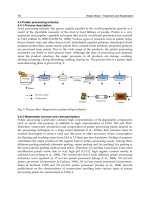
A robotic system was developed to automate the operation depicted in Fig. 19. The system
(Chen, 2000b) has a self-compliant mechanism that grips the part as an operator does with
two hands.
In its appearance, the robot does look like an operator in manipulating the part to achieve
desired contact states between the workpiece and the polishing tool, remove the right
amount of materials through force feedback control. It shortens the cycle time from 10
minutes for manual polishing to an average of 5.75 minutes, resulting in an improvement of
42.5% (Chen, 200b). Such an improvement mainly comes from two advantages that the robot
has over a human operator. Firstly the robot can exert a large force constantly while the
operator is unable to exert a large force for a long period. Secondly the robot is more
deterministic in planning the polishing paths after obtaining the part measurement (which is
part of 5.73 minutes cycle time), hence removes the iterations of inspect-then-polish in
manual operation and optimises and reduces the number of polishing passes.
Fig. 19. Robot grips the part with a compliant robot end-effector grips part.
Mobile Robots - State of the Art in Land, Sea, Air, and Collaborative Missions24
However this system’s force regulation during the polishing is still based on simple robot
positioning control. To increase or decrease the contact force which is detected by a spring
mechanism mounted inside the polishing tool, the robot moves the part in or out in
reference to the polishing tool. For a robot to be more adaptable to contact tasks, and
intrinsically safe, combined force and visual servoing is highly desired as if the operator
exerts a muscular force based on his/her tactile and force sensing intuitively.
As mobile robots make inroad into service and healthcare sectors where physical
interactions between robots and human beings take place, controlling robot movement,
particularly the movement of motivational parts (legs, feet, arms, fingers), intuitively based
force servoing is paramount. From engineering point of view, such intuitive control coupled
with flexible and compliant manipulator will enable a robot to execute a contact task, e.g.
help a patient lay down or use toilet, more efficiently and safely.
Another important aspect of intuitiveness lies in the way to learn skills and re-apply the
skills. Certainly, with the skills learnt, the operator can easily handle other types of parts,
and the skills are reusable. If a robot can emulate human intuitiveness, it should be able to
take simple instructions, observe the manual operation, practice under supervision, and
eventually master the skills to polish a 3D surface. Like a human operator, the robot can take
the skills learnt and be readily transferrable to another product line. There is still a long way
for robots to gain such intuitiveness.
6.3 Software designs
Software designs rely on a software platform to achieve desired cognition and intelligence.
Practical Robot Software Platforms. Various robot software platforms are already available
(e.g. Evolution Robotics). These systems can provide a cost-effective way of producing and
operating home-security robots, and will continue to increase in functionalities.
Robot Cognition and Artificial Intelligence. Advances robots with cognitive abilities,
artificial intelligence and associated technologies are vital for the development of intelligent,
autonomous robots for domestic applications.
In the future, mobile robots will require increased flexibility and robustness to the
uncertainties of the environment. Their predicted increased presence in daily life means that
they will have more tasks to perform and that these tasks will be diverse. An envisioned
approach to fulfil these requirements is to engineer the robots so that some of the processes,
inherent to the multiple functions to be performed, can be adapted based on contextual
knowledge. In other words, information from the robot’s surroundings gathered by multiple
sensors could be used to help the robot to achieve its tasks and even determine future tasks.
We can imagine a household robot deciding to clean the room when it “feels” that the room
is dirty.
Robotics is not the only field of research where contextual knowledge plays an important
role. In the literature, five specific tasks stand out as important for future research:
Behaviour, Navigation, Localization and Mapping, Perception.
Decision making based on contextual knowledge can easily be foreseen as useful in robotic
scenarios, the common scenario being to adapt the robot's behaviour to different situations
which the robot may encounter in operation. This is usually dealt with via plan selection,
hierarchical approaches to planning and meta-rules.
In the context of motion planning, the goal would be to find general solutions that can easily
be adapted in case of a change of context. Typically, however, to obtain effective
Mobiles Robots – Past Present and Future 25
implementations, specific algorithms and optimal solutions for specific cases are required.
The use of contextual knowledge can provide the necessary information to modify a general
technique so as to solve the problem at hand. In many cases, the navigation process is
included into a more complex process (for example exploration of the environment) where
the robot needs to find a target to reach and meet that target. It can easily be envisioned that
contextual knowledge can help set priorities when the robot has different missions to fulfil.
Contextual knowledge can also be useful for a robot to map its environment in an abstract
manner. Introducing language-based information (for example objects names, colors or
shapes) in addition to precise information about the environment can help the decision
making process as well as provide improved human-robot interactions. Contextual
knowledge may be used for selecting routines. The use of contextual knowledge can be
enlarged, for example, to decide when the robot can halt the mapping process and switch to
another function.
The use of contextual knowledge has a long tradition in Vision, both from a cognitive
perspective, and from an engineering perspective. Indeed, also robot perception can benefit
significantly from contextual knowledge. Moreover, it is through the sensing capabilities of
the robot that environmental knowledge can be acquired. In robot perception, normally,
iterative knowledge processing occurs: a top-down analysis, in which the contribution given
by the environmental and mission related knowledge helps the perception of features and
objects in the scene; a bottom-up analysis, in which scene understanding increases the
environmental knowledge
6.4 Hardware technologies
Affordable robots will continue to be built using fairly conventional hardware—off-the-shelf
electronic components, batteries, motors, sensors, and actuators. Materials and designs for
statue and motivational parts of the robots have not changed fundamentally, which has
been a significant limiting factor in advancing robotics technology and robot performances.
Table 2 compares the lifting capacity and lifting-to-weight ratio. For a typical articulated
industrial robot weighing 359 Kg, the lifting-to-weight ratio is about 0.03. The well-known
Honda humanoid robot lifts 1 Kg with two hands while a person of a similar body mass can
lift 20 Kg. Weighting lifting athletes can have lifting-to-weight capacity as high as 2.4. In this
regards, the robot construction is very inefficient compared to human build. Novel materials
and actuators are a key to building lighter robots for higher handling capacity.
Self weight
(Kg)
Lifting capacity
(Kg)
Lifting-to-weight
ratio
ABB IRB 2000 350 10 ~0.03
Honda Asimo 52 1 (for two hands) ~0.02
2008 Olympic Women 53
Kg Weightlifting Gold
53 126 (clean & jerk) ~2.4
A person having similar
weight to Asimo
52 ~ 20 ~0.4
Table 2. Robot versus human: lifting capacity
Mobile Robots - State of the Art in Land, Sea, Air, and Collaborative Missions26
Table 3 compares the motion range of robot wrist and human wrist. Generally speaking,
robots have better positioning repeatability and consistency than human beings. But human
beings accomplish precision tasks through powerful perception and intelligence.
Human Robot
Positioning repeatability ~ mm
~ Pm
Consistency Fair good
Wrist movement (roll, pitch,
yaw)
±90
o
, ± 40
o
, ± 20
o
±200
o
, ±120
o
, ±200
o
(ABB
IRB 2000)
Finger flexibility Dexterous (14 dof) Primitive
Mobility Excellent Poor
Dynamics & compliance Excellent Poor
Process knowledge Excellent Primitive
Observatory control Excellent Primitive
Table 3. Robot versus human: manoeuvrability and Intelligence
Robots generally have larger range of wrist movement. As illustrated in Table 3, the
industrial robot ABB IRB200 has ±200
o
, ±120
o
, and ±200
o
movement for roll, pitch and yaw
respectively, as opposed to ±90
o
, ± 40
o
, and ± 20
o
for human wrists. However the robot’s
superiority does not translate to better dexterity. In fact a human operator is much more
dexterous in manipulating objects as in the case of polishing 3D surface. This arises from: 1)
natural coordination of two hands, and more importantly our fingers, a total of 14 degrees
of freedom, are separately actuated. In the case of Asimo, five fingers are driven by the same
motor, which can only achieve limited handling dexterity and coordination.
As robots will interact more and more with human, they will need improved mobility and
movement capabilities. To achieve human-like movements, robots will have to become
much more complex than they are today. The development of these enhanced robots
represents an excellent challenge to researchers. However, increasing the complexity of
robots’ hardware and structure should not be done by neglecting reliability of those same
robots. To avoid these problems, the simplification of robots mechatronics will be necessary.
Although everyone working on robots acknowledges that, in reality, the design of the
mechanical structure greatly affects the performance and controllability, general
investigations of the relationship between a robot’s mechanical structures and its
controllability and reliability have been relatively scarce. This is a fundamental omission in
the field of robotics. The research direction would be to find a unified method to create
suitable mechanics for autonomous mobile robots that provide good dynamic performance,
as well as simplicity and reliability.
6.5 Service robots – a disruptive technology in decades to come
Fig. 20 shows the technology road map of autonomous systems (SRI, 2008). Mobile robots
are evolving from unmanned, remote controlled, semi-autonomous, to full autonomous
systems. In this evolution, mobile robots require greater mobility, and higher intelligence.
Mobiles Robots – Past Present and Future 27
Fig. 20. Technology Roadmap: Service Robotics (SRI, 2008)
The highly integrated systems comprising machines, sensors, computers, and software that
have action and reasoning capabilities may relieve human from working in hazardous
operations such as welding, plant dismantlement, to operate cutting tools from a safe
distance. Robots could offer human-machine interfaces as easy to operate as the current
personal computer. Fig. 21 shows a human augmented robotics welding system. It allows
the operator to carry out welding remotely.
As the elderly population increases, there are greater and more pressing societal needs of
health care and personal assistance at the society and family level. As more people live to
the oldest ages, there may also be more who face chronic, limiting illnesses or conditions,
such as arthritis, diabetes, osteoporosis, and senile dementia. According to OECD statistics
(EURON, 2004), one third to one-half of health spending is for elderly people. Elderly
people with varying limiting conditions become dependent on others for help in performing
the activities of daily living. These needs call for much faster advancement of service robots
that can assist elderly people to perform everyday activities such as bathing, getting around
inside the home, and preparing meals.
Mobile Robots - State of the Art in Land, Sea, Air, and Collaborative Missions28
Fig. 21. Human augmented welding robot ( />99/robot_story.htm)
Fig. 22. Health spending quantities (Source: OECD)
According to the IFR (International Federation of Robotics), a service robot is a robot which
operates semi or fully autonomously to perform services useful to the well being of humans
and equipment, excluding manufacturing operations. Apart from caring for elderly people,
service robots will expend into many aspects of the society. A robot nanny may look after
children, providing more interactive learning environment (Figure 23.).
Mobiles Robots – Past Present and Future 29
Fig. 23. Robot nannies look after children (blog.bioethics.net.)
Robots may replace nurses by performing jobs like dispensing drugs, taking temperatures
and cleaning up wards (Figure 24.). The humanoid will make caring for patients cheaper
and safer.
Fig. 24. A robot nurse carries a patient (bp2.blogger.com)
In developing the National Intelligence Council's Global Trends 2025, SRI Consulting
Business Intelligence (SRIC-BI) was commission to identify six potentially disruptive civil
technologies that could emerge in the coming fifteen years. The six disruptive technologies
were identified through a process carried out by technology analysts from SRIC-BI's
headquarters in Menlo Park, California, and its European office in Croydon, England. The
full finds are published in the recent conference report (SRI, 2008). From 102 potentially
disruptive technologies, the following six disruptive technologies have been identified:
Mobile Robots - State of the Art in Land, Sea, Air, and Collaborative Missions30
Biogerontechnology
Energy Storage Materials
Biofuels and Bio-Based Chemicals
Clean Coal Technologies
Service Robotics
The Internet of Things.
Apart from military applications, the report noted the significant impact of service reports
on elder-care applications. It is envisioned that the development of human-augmentation
technologies will allow robots to work alongside humans in looking after and rehabilitating
people. What is interesting is that some of technologies have dual uses. As opposed to
human beings who convert food to energy, robots rely on external power supply. Energy
storage, which is also identified as a disruptive technology, has high relevance to service
robots as well.
7. Conclusions
Humankind has dreamt of robots being faithful slaves to carry various mundane or
intelligent operations since the ancient times. Although there is no universally accepted
definition for “robot”, the key elements of a “robot” lie in “its ability to perform functions”
and “its ability to move”. To possess the two basic abilities, a robot requires intellect,
actuation, mobility (statue and motivational), sensors, and communication. There is
correspondence between robots and human in terms of these functional blocks. Robotics
and robot intelligence researchers benefit from understanding of biological systems in
developing biologically inspired robots that can emulate the naturally gifted abilities of
these subjects.
Mobile robots, as opposed to fix based industrial robots, have huge potential to impact the
society. The market for mobile robots is increasing. As such, there has been an explosion of
research activities in mobile robots since the emergence of Shakey and Stanford Cart in
1970s. The field has witnessed a variety of attempts to develop mobile robots for critical
missions, being on land, underwater or in the air. The applications range from military, to
civil and service. Great progress has been achieved in design, perception and control. In
terms of bio robots, many techniques have been developed to equip robots with efficient
mobility and locomotion. Nevertheless, because of technological limitations, these systems
mostly are still confined to laboratory exploitations. The deficiencies in current robotics
technology have been key limiting factors in wider acceptance and adoption of mobile
robots. Further research and development efforts are required to tackle many challenges and
close the gap between proof-of-concept and actualisation.
Wide applications of robots require standardisation and rationalisation of programming
languages, system architecture, mechanical/electrical/control interfaces for plug-and-play.
The key issues are connectivity, modularity, portability and interchangeability.
The existing robots have limited intuitive learning ability. They have no or little ability to
“grow”, a natural gift in human. Once programmed to perform one function, robots have
little self adaptation to a new function or a variation of the same function. A breakthrough
in the theories of intuitive learning and observatory control would make the robots more
human-like intellectually, not just physically. This is tied to the ability for a robot to gain
contextual knowledge from interacting with environments. Information from the robot’s
Mobiles Robots – Past Present and Future 31
surroundings gathered by multiple sensors could be used to help the robot to achieve its
tasks and even determine future tasks. Furthermore robots grow intellectually so to operate
in new environments.
At present, robots are still far more inferior to biological systems in terms of dexterity,
coordination, lifting capacity, etc. Hardware technology, such as novel materials, actuation,
and mechanical design holds the key to enhance the robot capabilities.
As the society is aging, there are pressing needs for service robots to help elderly people
gain greater independence for activities encountered in daily life. In addition to military
applications and exploitations, service robots will fulfil different roles in the society, being
robot security guard, robot nannies, robot tour guide, robot nurse, etc. In decades to come,
they may well emerge as a disruptive technology to impact the society greatly.
8. Acknowledgement
The authors wish to thank Mr. John Fleming for express ordering of newest reference books,
and Christophe Tricaud and Mervin Chandrapal for their assistance in preparing this
chapter.
9. References
Bekey G.; Ambrose R.; Kumar V.; Lavery D.; Sanderson A.; Wilcox B.; Yuh J. & Zheng Y.
(2008). Robotics: State of the Art and Future Challenges, Imperial College Press, ISBN
978-1-84816-006-4.
Calisia D.; Iocchi L.; Nardia D.; Scalzoa C. M. & Ziparoa V. A. (2008). Context-based design
of robotic systems, Robotics and Autonomous Systems, Vol. 56, No. 11, (November
2008), pp. 992-1003
Chao, H.; Cao, Y. & Chen Y. Q. (2007). Autopilots for Small Fixed-Wing Unmanned Air
Vehicles: A Survey. Proceedings of International Conference on Mechatronics and
Automation, 2007, pp.3144-3149, 5-8 Aug. 2007
Chen, X.Q., Gong, Z.M., Huang, H., Ge S.Z., and Zhou L.B. (2000a) “Process Development
and Approach for 3D Profile Grinding and Polishing” in Advanced Automation
Techniques in Adaptive Material Processing, Eds: X.Q. Chen, R. Devanathan &
A.M. Fong, ISBN 981-02-4902-0, World Scientific, Singapore, pp. 19-54.
Chen, X.Q., Gong, Z.M., Huang, H., Ge S.Z., and Zhou L.B. (2002b) “Adaptive Robotic
System for 3D Profile Grinding and Polishing” in Advanced Automation Techniques in
Adaptive Material Processing, Book edited by: Chen, X.Q., Devanathan R., and Fong,
A.M., ISBN 981-02-4902-0, World Scientific, Singapore, pp. 55-90.
Department of Defense (2007). Unmanned systems soadmap, 2007-2032,
/>
Delcomyn F. (2007) “Biologically Inspired Robots”, Bioinspiration and Robotics: Walking and
Climbing Robots, Book edited by: Maki K. Habib, ISBN 978-3-902613-15-8, I-Tech,
Vienna, Austria, EU, September 2007, pp. 279 – 300.
Ecole Polytechnique Federale de Lausanne (2008). Course on mobile robots,
/>
EURON, European Robotics Research Network (2004), EURON Research Roadmaps, 23 April
2004.
Mobile Robots - State of the Art in Land, Sea, Air, and Collaborative Missions32
Floreano D.; Godjevac J.; Martinoli A.; Mondada F. & Nicoud J. D. (1998). Design, Control,
and Applications of Autonomous Mobile Robots, Advances in Intelligent Autonomous
Agents, Boston : Kluwer Academic Publishers, 1998
Laumond, J. P. (1999). Robot Motion Planning and Control. />
book.html
Li, Z. & Canny, J. F. (1993). Nonholonomic Motion Planning, The Springer International Series
in Engineering and Computer Science, Vol. 192, ISBN: 978-0-7923-9275-0
Liu S. C.; Tan D. L.; & Liu G. J. (2007). Formation Control of Mobile Robots with Active
Obstacle Avoidance, Acta Automatica Sinica, Vol. 33, No. 5, (May 2007), pp. 529-
535,
Kara, D. (2006). Global trends in the consumer robotics market, http://
www.roboticstrends.com/
Kaikkonen J.; Mikelainen T. & Hakala H. (1991). Advanced Design Methods and Tools for
Mobile Robot Development, In Proceedings of IEEE/RSJ International Workshop on
Intelligent, Robots and Systems lROS '91. Nov. 3-5, 1991
Kim, S., Spenko, M., Trujillo, S., Heyneman, B., Santos, D., Cutkosky, M.R. (2008) “Smooth
Vertical Surface Climbing With Directional Adhesion”, IEEE Transactions on
Robotics, Volume: 24, Issue: 1, pp. 65-74
Nassiraei A. & Ishiia K. (2007). Concept of Intelligent Mechanical Design for Autonomous
Mobile Robots, Journal of Bionic Engineering, Vol. 4, No. 4, December 2007, pp. 217-
226
Ohio State University, College of Engineering (1923) "Pilotless Plane", Ohio State Engineer,
vol. 6, no. 3 (April, 1923), page 19.
Patnaik, S. (2007). Robot Cognition and Navigation – An Experiment with Mobile Robots,
Springer, ISBN: 978-3-540-23446-3, Berlin Heidelberg New York.
Shen, W., Gu, J., and Shen, Y. (2005) “Proposed wall climbing robot with permanent
magnetic tracks for inspecting oil tanks,” in Proc. IEEE Int. Conf. Mechatronics and
Automation, Niagara Falls, Canada, July 2005, pp. 2072-2077.
SRI Consulting Business Intelligence, under the auspices of the National Intelligence
Council (2008), Disruptive Civil Technologies - Six Technologies with Potential Impacts
on US Interests out to 2025, Conference Report CR 2008-07, April 2008.
Wagner, M., Chen, X.Q., Wang, W.H. and Chase J.G. (2008), “A novel wall climbing device
based on Bernoulli effect”, Proc 2008 IEEE/ASME International Conference on
Mechatronic and Embedded Systems and Applications (MESA08), ISBN: 978-1-
4244-2368-2, Beijing, China, October 12-15, pp. 210-215.
WinterGreen Research, Inc. (2007), />
Zhao, Y., Fu, Z., Cao, Q., and Wang, Y. (2004) “Development and applications of wall-
climbing robots with a single suction cup”, Robotica, Cambridge University Press,
Volume 22, pp. 643–648.
2
A Field Robot with Rotated-claw Wheels
Ronggang Yue, Jizhong Xiao
2
*, Kai Li, Jun Du, Shaoping Wang
1
Beihang University
China
2
City University of New York
United States of American
1. Introduction
With the development of space science and technology, some countries have launched
unmanned planetary exploration programs. Because planet surfaces are rough and
formidable, planetary exploration rovers were used as a versatile and safe alternative to
manned space missions to explore the planets. In recent years, many types of planetary
rovers were developed including tracked type, legged type, and wheeled type, etc. (Li et al.,
2005). Because wheeled rovers are well suited to provide smooth motion and offer a high
payload capacity, they become the most popular and the mainstream in current rovers
(Salemo et al., 2002).
In order to deal with the rough terrains of planetary surfaces, researchers put most of the
efforts in designing new structure of rover body, but give less attention to new Types of
wheels. Currently, three main classes of wheels are used in planetary rovers as follows:
(1) Representations are the wheels of Mars exploration rover Spirit (Lindemann et al.,
2006) developed by JPL and Japanese rover Micro5 (Takashi et al., 2003). This type of wheel
has a circular shape with a lot of transverse striae spaced evenly around the wheel to
increase the friction between ground and the wheel. The wheels are commonly used in most
of the rovers that can move smoothly and turn around agilely. But its fatal disadvantage is
that it can not scale the step whose height is larger than the radius of the wheel, also it can
not cross the ditch whose width is larger than the diameter of the wheel.
(2) Flexible flake wheel. The representation is the wheel of Mars rover made by Toshiba in
Japan (Liu et al., 2002). This kind of wheel is circular too, but the difference is that there are
lots of flexible flake spaced evenly around the wheel. Compared with the first type wheel,
this wheel increases buffering, and it can traverse over the step whose height is larger than
the radius of the wheel. However, it can not cross the ditch whose width is larger than the
diameter of the wheel.
(3) Multiple planetary wheel. A representative example is the wheel of Lunar rover
developed by Harbin Institute of Technology (HIT) in China. The lunar rover uses planetary
wheel which consists of three small circular wheels (Deng et al., 2003; Deng et al., 2004).
When the lunar rover moves on flat terrain, only two small wheels touch ground. Once it
encounters a big obstacle or step, the three small wheels revolve around the public center of
the wheels to traverse over the obstacle. This type of wheel overcomes the shortcomings of
Mobile Robots - State of the Art in Land, Sea, Air, and Collaborative Missions34
conventional circular wheels, and can climb over the step that is higher than diameter of the
small wheel. However, this type of wheel makes the robot hard to make turns.
In this paper, we introduce a field robot (named as Rabbit) using the rotated-claw wheel
have demonstrated the superiority over the conventional wheels. The analysis and testing
results show that the innovative rotated-claw wheel can move steadily, turn around agilely,
and climb the step whose height is larger than the radius of the wheel which has
demonstrated.
2. Design of the Rabbit
The basic requirements for an excellent field robot are motion stability, and strong capability
of climbing obstacles or slopes. We designed a field robot prototype named as Rabbit whose
motion is based on 4 rotated-claw wheels attached by "bogie levers" to the chassis. Figure 1
shows its electrical diagram and Figure 2 shows the picture of the robot whose weight is
10.5Kg and outline dimension is 57cm×43cm×31cm. The body of Rabbit is mounted to the
rocker through a differential mechanism. Rabbit is driven by 8 DC brushed motors that are
controlled by a DSP controller. Each motor drives a series of stages of gearing that result in
the final torque-speed relationship of the actuator. The total gear reduction rate for each
actuator is 246:1. An encoder on each motor is utilized for sensing the rotation speed and
determining steering angle. Under average load conditions, the wheel rotates at 24.4 rounds
per minute, which results in a nominal vehicle speed of 15.3 cm/s with the 12 cm diameter
wheels. In order to study the motion performance, an accelerator and an inclinometer are
installed in the robot prototype.
Fig. 1. Schematic of Rabbit’s electrical diagram
A Field Robot with Rotated-claw Wheels 35
Fig. 2. The field robot prototype named as Rabbit
Due to the rotated-claw wheel is an innovative design. We would like to introduce principle
and design of the wheel in detail.
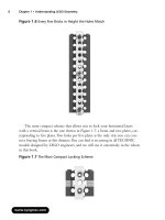
3. Design of rotated-claw wheel
3.1 Principle of the rotated-claw wheel
The schematic diagram of the rotated-claw wheel is shown in Figure 3. In order to ensure
the motion stability, turning flexibility, and obstacle-climbing capability, the wheel is
designed as traditional circular structure with six sets of claw mechanism evenly installed
around the wheel’s outer skirt. Each set of claw mechanism consists of claw, claw axle, gag
lever post and draught spring. Each claw can swing round its axle. The claw is in open state
under the effect of draught spring and gap lever post when it doesn’t touch the ground, and
the claw swings into the wheel body under the effect of rover’s weight when it touches the
ground, which improves bumpy motion caused by hexagon effect.
Fig. 3. Schematic diagram of the rotated-claw wheel
3.2 Motion stability analysis
As shown in figure 3, the claw can swing into the wheel body smoothly when the wheel
rotates in anticlockwise direction, and the hexagonal effect of the wheel gives little influence
on the stability of the rover. However, when the wheel rotates in clockwise rotation, the
claw may disturb the stability of the wheel and cause the rover jounce. Therefore, we must
analyze the stress of the wheel and select design parameters carefully to avoid this problem
in the case of clockwise rotation.
Mobile Robots - State of the Art in Land, Sea, Air, and Collaborative Missions36
When design the wheel, we first determine the claw dimensions and the distance between
each claw axle and wheel’s center, then adjust the position of gag lever post. Figure 4 shows
the process of a claw touching the ground when the wheel rotates in clockwise direction on
flat terrain. There are two cases about angle DŽ in Figure 4. One is the case when angle DŽ is
larger than 90°, the other is the case when angle DŽ is less than 90°. We will discuss the two
cases respectively.
(a)First critical state (b) Moving forward (c) Second critical state
Fig. 4. Rotation in clockwise direction on flat terrain of rotated-claw wheel
3.2.1 When angle Ȗ is larger than 90°
Figure 5(a) shows the critical state when a claw tip touches the ground while the wheel
leaving the ground. At this time instance only point A supports the wheel, i.e., only point A
gets supporting force from the ground. Taking the claw touching the ground as an object,
we can get the stress analysis shown in Figure 5(b), in which the wheel and the claw are
expressed in dashed lines and the claw is simplified as line segments AOB and the draught
spring is simplified as line BC.
Stress analysis in Figure 5(b) shows that the claw satisfies the following equation:
31211
coscossin lNFlflNl
E
D
D
(1)
where, N is the acting force of ground to wheel at point A; N
1
is the acting force of gag lever
post to claw; l
1
is the length of line OA; l
2
is the length of line OB; l
3
is the level distance of
force N
1
; ǂ is the angle between line OA and plumb line; ǃ is the angle between line OB and
the line perpendicular to line BC; f is the friction between point A and ground; F is the pre-
setting pulling force of spring BC.
(a) Motion state (b) Stress analysis
Fig. 5. Stress analysis when angle DŽ is larger than 90°
A Field Robot with Rotated-claw Wheels 37
Because it is in a balance state, the claw cannot swing around point O should angle DŽ is
larger than 90°, and thus the claw cannot swing into the wheel body. Now we get the first
condition ensuring the claw swing into the wheel body smoothly is that angle DŽ must be less
than 90°. We can adjust numerical values of l
1
, l
2
, l
3
, ǂ, ǃ to make DŽ be less than 90°.
3.2.2 When angle Ȗ is less than 90°
There are two critical states as illustrated in Figure 4(a) and Figure 4(c).
(1) First critical state
Figure 6 shows the First critical state-when the wheel is on the point of leaving the ground,
in which a claw tip touches the ground, and its weight acts on point A. At this time instance,
only point A supports the wheel. Taking the claw touching the ground as an object, we can
get the stress analysis shown in Figure 6(b), in which the wheel and the claw are expressed
in dashed lines, the claw is simplified as line segments AOB and the draught spring is
simplified as line BC.
(a) Motion state (b) Stress analysis
Fig. 6. Stress analysis at the first critical state
In Figure 6, the claw touching the ground must swing around the point O clockwise if the
wheel is to rotate clockwise smoothly. In order to satisfy this requirement, every claw must
satisfy the following equations:
°
°
¯
°
°
®
'
|
!
Nf
xkF
GN
fllFNl
P
DED
minmin
12min1
coscossin
(2)
where, N is the acting force of ground to wheel at point A; l1 is the length of line OA; l
2
is the
length of line OB; ǂ is the angle between line OA and plumb line; ǃ is the angle between line
OB and the line perpendicular to line BC; F
min
is the pre-setting pulling force of spring BC; f
is the friction between point A and ground; G is the gravity force acting on the single wheel
from the rover that is approximate to N; k is the elastic coefficient of spring BC;
△
x
min
is the
extension of spring BC;
μ
is the coefficient of sliding friction between point A and ground.
Mobile Robots - State of the Art in Land, Sea, Air, and Collaborative Missions38
Then we can get the following inequation:
D
P
E
D
coscossin
12min1
GllxkGl '!
(3)
Inequation (3) is the first criterion that makes the claw swing into the wheel body freely and
ensures the wheel rotate clockwise smoothly.
(2) Second critical state
The second critical state is shown in Figure 7(b), when the excircle of the claw is tangent to
the road surface, in which its weight acts on point A and the other part of the wheel doesn’t
touch the ground.
(a) Motion state (b) Stress analysis
Fig. 7. Stress analysis at the second critical state
In Figure 7, the claw must be inside of the profile of the wheel body if the wheel is to rotate
clockwise smoothly. Every claw must satisfy the following equations:
°
¯
°
®
'
|
maxmax
'
1
'
2max
sincos
xkF
GN
NllF
DE
(4)
where, F
max
is the pulling force of spring BC; l
1
is the length of line OA; l
2
is the length of line
OB; ǂ’ is the angle between line OA and plumb line; ǃ’ is the angle between line OB and the
line perpendicular to line BC; N is the acting force of ground to wheel at point A; G is the
gravity force of the single wheel; k is the elastic coefficient of spring BC;
△
x
max
is the
extension of spring BC.
Then we can get the following inequation:
'
1
'
2max
sincos
DE
Gllxk '
(5)
Inequation (5) is the second criterion that makes the claw swing into the wheel body freely
and ensures the wheel rotate clockwise smoothly.
In summary, when designing the rotated-claw wheel, the distance between point O and the
center of the wheel should be chosen appropriately. When the claw touches the ground, the
angle DŽ should be less than 90° as shown in Figure 5(a). At the same time, appropriate
numerical values of G, l
1
, l
2
, ǂ, ǃ, ǂ‘, ǃ’,
△
x
min
,
△
x
max
should be chosen to satisfy inequations
(3) and (5). These criteria ensure the wheel rotate in clockwise direction steadily and reduce
jounce (Yue et al., 2007).
A Field Robot with Rotated-claw Wheels 39
3.3 Obstacle-climbing analysis
Conventional circular wheels cannot scale the step whose height is larger than the radius of
the wheel. In Figure 8, the step height is H
1
, and the radius of the conventional circular
wheel is R. If the wheel wants to traverse over the step, H
1
must be less than R. The rotated-
claw wheel overcomes this shortcoming. In Figure 9, the step height is H
2
, and the radius of
the rotated-claw wheel is still R. However, due to the existence of the claw, wheel can scale
the step whose height is larger than the radius of the wheel by h, and h can be designed
larger than zero by choosing suitable numerical values of l
1
, l
2
, ǂ, ǃ, and distance between
point O and wheel’s center. From the analysis, we can claim with confidence that the
obstacle-climbing capability of the rotated-claw wheel is improved in comparison with the
conventional circular wheels. Real experimental results will verify the performance.
Fig. 8. Sketch drawing of circular wheel climbing a step
Fig. 9. Sketch drawing of rotated-claw wheel climbing a step
3.4 Structure design of rotated- claw wheel
Based on the criteria mentioned above, this paper designed the three-dimensional model of
the rotated-claw wheel shown in Figure 10 that includes a steering mechanism and the
obstacle-climbing mechanism (rotated-claw). In order to enhance the friction between the
wheel and ground, grooves are constructed around the wheel in even space. The deigned
diameter of the wheel is 120 mm and its width is 60 mm. Dimensions of the claw is shown in
Figure 11, which make DŽ be less than 90°.
Mobile Robots - State of the Art in Land, Sea, Air, and Collaborative Missions40
Fig. 10. Three-dimensional model of the rotated-claw wheel
Fig. 11. Dimensions of the claw
4. Performance test of Rabbit
In order to test environmental adaptability of Rabbit, the experiments are conducted on
various terrain, including surfaces of bituminous macadam, dry soil, step, slope, and
simulated lunar soil. All of the data were collected when Rabbit moves at full speed
4.1 Motion stability performance
The motion stability analysis reveals that the six claws may cause a little jounce when the
rotated-claw wheel rotates in clockwise direction, while smooth motion is guaranteed in
anticlockwise rotation. We conducted experiments to evaluate the motion stability
performance by commanding the Rabbit robot move on flat ground of bituminous
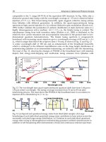
macadam. Figure 12 shows the acceleration curve of Rabbit in plumb direction when the
rotated-claw wheels rotate in clockwise direction. The acceleration varies from -0.39g to
0.46g. Figure 13 gives the acceleration curve of Rabbit in plumb direction when the wheels
make anticlockwise rotation, it shows that the acceleration changes from -0.13g to 0.16g.
Figure 14 gives the acceleration curve in plumb direction when Rabbit rotates with the claws