Mobile Robots - Moving Intelligence Part 3 pps
Bạn đang xem bản rút gọn của tài liệu. Xem và tải ngay bản đầy đủ của tài liệu tại đây (525.94 KB, 40 trang )
Combined Torque and Velocity Control of a Redundant Robot System 71
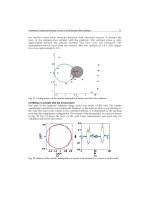
the smaller circles show obstacles detected with ultrasonic sensors. F denotes the
force of the obstacle that collides with the platform. The collision place is only
approximate because the obstacle position and force were not measured. The
manipulator moved away from the obstacle after the collision in 0.8 s. The impact
force was approximately 4 N.
Fig. 21. Configuration of the mobile manipulator before and after the collision.
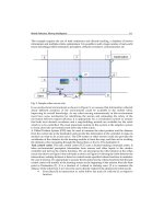
5.6 Motion in contact with the environment
One part of the trajectory reference (large circle) was inside of the wall. The mobile
manipulator end-effector was tracking the trajectory to the wall and than it was pressing to
the wall. The force of the contact is not controlled directly. It is dependent on the tracking
error and the manipulator configuration. The motion of the manipulator in contact is shown
in Fig. 22. Fig. 23 shows the force on the wall. Force measurement was used only for
validation and not for the control.
Fig. 22. Motion of the mobile manipulator in space with obstacles in contact with the wall.