Mechanical Engineer''''s Reference Book 2011 Part 9 pptx
Bạn đang xem bản rút gọn của tài liệu. Xem và tải ngay bản đầy đủ của tài liệu tại đây (2.73 MB, 70 trang )
Lubricants
(oils
and
greases)
9/11
Engine type
Oil
qualily
Conditionis
API
US
Military
test
procsdurci
CCMC
specilicalions
Addilive
Ireatment
level
-
Gasoline
I
Diesel
High
Low
1
Low
Hiah
Severe
High
Low
Nil
1
Law
High
I
SHPD
=
Super High
Pnrlormance
Diesel
PQ
=
Passenger
(Car)
Diesel
Figure
9.6
Approximate relationship between classifications
and
test procedures
pressure pumps have been developed. Additionally, systems
have to provide incrseased power densities, more accurate
response, better reliability and increased safety. Their use in
numerically controlled machine tools and other advanced
control systems creates the need
for
enhanced filtration. Full
Bow filters as fine as
1-10
pm
retention capability are now to
be found in many hydraulic systems.
With the trend toward higher pressures in hydraulic systems
the loads on unbalanced pump and motor components become
greater and this, coupled with the need
for
closer fits to
contain the higher pressures, can introduce acute lubrication
problems. Pumps,
one
of
the main centres of wear, can be
made smaller if they can
run
at higher speeds
or
higher
pressures, but this is only possible with adequate lubrication.
For this reason, a fluid with good lubrication properties is used
so
that ‘hydraulics’ is now almost synonymous with ‘oil
hydraulics’ in genera1 industrial applications. Mineral oils are
inexpensive and readily obtainable while their viscosity can be
matched
to
a particular job.
The hydraulic oil must provide adequate lubrication in the
diverse operating conditions associated with the components
of
the various systems.
It
must function over an extended
temperature range and sometimes under boundary conditions.
It
will be expected to provide a long, trouble-free service life;
its chemical stability must therefore be high. Its wear-resisting
properties
must
be capable
of
handling the high loads in
hydraulic pumps. Additionally, the oil must protect metal
surfaces
from
corrosion and it must both resist emulsification
and rapidly release entrained air that, on circulation, would
produce foam.
Mineral oil alone,
no
matter how high its quality, cannot
adequately carry out all the duties outlined above and hence
the majority of hydraulic oils have their natural properties
enhanced by the incorporation of
four
different types
of
additives. These are: an anti-oxidant, an anti-wear agent, a
foam-inhibitor and an anti-corrosion additive.
For
machines in
which accurate control is paramount, or where the range
of
operating temperatures is wide
-
or both
-
oils
will be formu-
lated to include a
VI
improving additive as well.
9.2.6.1 Viscosity
Probably the most important single property of a hydraulic oil
is its viscosity. The most suitable viscosity for a hydraulic
system is determined by the needs of the pump and the circuit;
too low a viscosity induces back-leakage and lowers the
pumping efficiency, while too high a viscosity can cause
overheating, pump starvation and possibly cavitation.
9.2.6.2 Viscosity
Index
It
is desirable that a fluid’s viscosity stays within the pump
manufacturer’s stipulated viscosity limits, in order
to
accom-
modate the normal variations
of
operating temperature. An
oil’s viscosity falls as temperature rises; certain oils, however,
are less sensitive than others to changes of temperatures. and
these are said to have a higher VI. Hydraulic
oils
are formu-
lated from base oils
of
inherently high
VI,
to minimize changes
of
viscosity in the period from start-up to steady running and
while circulating between the cold and hot parts of a system.
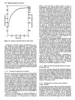
3.5-
3.0-
/
arise; a high figure indicates a high level
of
compatibility. This
system has been superseded by the more accurate Seal Com-
patibility Index
(SCI),
in
which the percentage volume swell
of
a ‘standard‘ nitrile rubber is determined after an immersion
test in hot oil.
PRESSURE,
ATMOSPHERES
ABS
Figure
9.6
9.2.6.3
Effects
of
pressure
Pressure has the effect of increasing an oil’s viscosity. While in
many industrial systems the working pressures are not high
enough to cause problems in this respect, the trend towards
higher pressures in equipment is requiring the effect to be
accommodated at the design stage. Reactions to pressure are
much the same as reactions to temperature,
in
that an oil
of
high
VI
is less affected than one
of
low
VI.
A
typical hydraulic
oil’s viscosity
is
doubled when its pressure is raised from
atmospheric to
35
000
kPa (Figure
9.6).
9.2.6.4 Air in the
oil
In
a system that is poorly designed or badly operated, air may
become entrained in the oil and thus cause spongy and noisy
operation. The reservoir provides an opportunity for air to be
released from the oil instead
of
accumulating within the
hydraulic system. Air comes to the surface as bubbles, and if
the resultant foam were to become excessive it could escape
through vents and cause
loss
of
oil. In hydraulic oils, foaming
is
minimized by the incorporation
of
foam-breaking additives.
The type and dosage of such agents must be carefully selected,
because although they promote the collapse of surface foam
they may tend to retard the rate
of
air release from the body
of
the oil.
9.2.6.5 Oxidation stability
Hydraulic
oils
need to be
of
the highest oxidation stability,
particularly for high-temperature operations, because oxida-
tion causes sludges and lacquer formation.
In
hydraylic oils, a
high level
of
oxidation stability is ensured by the use
of
base
oils of excellent quality, augmented by a very effective combi-
nation of oxidation inhibitors.
A
very approximate guide to an oil’s compatibility with
rubbers commonly used
for
seals and hoses is given by the
Aniline Point, which indicates the degree
of
swelling likely to
9.2.6.6 Fire-resistant fluids
Where fire is a hazard, or could be extremely damaging,
fire-resistant hydraulic fluids are needed. They are referred
to
as ‘fire resistant’ (FR)
so
that users should be under
no
illusions about their properties. FR fluids do not extinguish
fires: they resist combustion or prevent the spread
of
flame.
They are not necessarily fireproof, since any fluid will even-
tually decompose if its temperature rises high enough. Nor are
they high-temperature fluids, since in some instances their
operating temperatures are lower than those of mineral oils.
FR fluids are clearly essential in such applications as electric
welding plants, furnace-door actuators, mining machinery,
diecasters, forging plant, plastics machinery and theatrical
equipment. When leakage occurs in the pressurized parts
of
a
hydraulic system the fluid usually escapes in the form of a
high-pressure spray.
In
the case of mineral oils this spray
would catch fire if it were to reach a source of ignition, or
would set up a rapid spread
of
existing flame. FR fluids are
therefore formulated
to
resist the creation of flame from a
source
of
ignition, and
to
prevent the spread of an existing
fire.
Four main factors enter into the selection
of
a fire-resistant
fluid:
1.
The required degree
of
fire-resistance
2.
Operational behaviour in hydraulic systems (lubrication
performance, temperature range and seal compatibility, for
example)
3.
Consideration
of
hygiene (toxicological, dermatological
and respiratory effects)
4.
cost
9.2.6.1 Types
of
fluid
The fluids available cover a range of chemical constituents,
physical characteristics and costs,
so
the user is able to choose
the medium that offers the best compromise for operational
satisfaction, fire-resistance and cost effectiveness. Four basic
types
of
fluid are available and are shown in Table
9.4.
In
a fully synthetic FR fluid the fire resistance is due to the
chemical nature
of
the fluid; in the others it is afforded by the
Table
9.4
CETOP
classifications
of
fire-resistant hydraulic fluids
Class Description
HF-A Oil-in-water emulsions containing a maximum
of
20%
combustible material. These usually
contain
95%
water
Water-in-oil emulsions containing a maximum
of
60%
combustible material. These usually
contain
40-45%
water
Water-glycol
solutions.
These usually contain at
least
35%
water
Water-free fluids. These usually refer to fluids
containing phosphate esters, other organic
esters or synthesized hydrocarbon fluids
HF-B
HF-C
HF-D
CETOP: ComitC European
des
Transmissions Oleohydrauliques et
Pneumatiques.
Lubricants
(oils
and greases)
9/13
equipment. Condensation corrosion effect
on
ferrous metais,
fluid-mixing equipment needed, control
of
microbial infection
together with overall maintaining and control of fluid dilution
and the disposal
of
waste fluid must also be considered.
Provided such attention is paid to these design and operating
features, the cost reductions have proved very beneficial
to
the
overall plant cost effectiveness.
presence of water. The other main distinction between the two
groups is that the fully synthetic fluids are generally better
lubricants and are available for use at operating temperatures
up
to
150"C,
but are less likely to be compatible with the
conventional sealing materials and paints than are water-based
products.
When a water-based fluid makes contact with a flame or aaa
hot surface its water component evaporates and forms a steam
blanket which displaces oxygen from around the hot area, and
this obviates the risk
of
fire. Water-based products all contain
at least 35% water. Because water can be lost by evaporation,
they should not be subjected
to
operating temperatures above
about 60°C. Table
9.5
shows a comparison
of
oil and
FR
fluids.
9.2.6.8
High water-based hydraulic fluids
For a number
of
years
HF-A
oil-in-water emulsions have been
used as a fire-resistant hydraulic medium for pit props.
Concern over maintenance
costs
and operational life has
created interest in a better anti-wear type Buid. Micro-
emulsions are known to give better wear protection than the
normal oil-in-water emulsions. At the same time the car
industi-y, in attempts to reduce Costs especially from leakages
on production machinery, has evaluated the potential for
using HWBHF
in
hydraulic systems.
As
a result, in many parts
of
industry, not only those where fire-resistant hydraulic fluids
are needed, there
is
a increasing interest in the use of
HWBHIF.
Such fluids, often referred to as
5/95
fluid (that being the
ratio
of
oil to water), have essentially the same properties as
water with the exception
of
the corrosion characteristics and
the boundary lubrication properties which are improved by
the
oil
and other additives. The advantages
of
this type
of
fluid
are fire resistance, lower fluid cost, no warm-up time, lower
power consumption and operating temperatures, reduced
spoilage of coolant, less dependence
on
oil together with
reduced transport, storage, handling and disposal costs, and
environmental benefits.
In considering these benefits the the user should not over-
look
the constraints in using such fluids. They can be summa-
rized as limited wear and corrosion protection (especially with
certain metals), increased leakage due to its low viscosity,
limited operating temperature range and the need for addi-
tional mixing and in-service monitoring faciiities.
Because systems are normally
not
designed for use with this
type
of
fluid, certain aspects should be reviewed with the
equipment and fluid suppliers before a decision
to
use such
tluids can be taken. These are compatibility with filters, seals.
gaskets, hoses, paints and any non-ferrous metals used in the
Table 9.5
Comparison
of
oil
and
FR
fluids
Fire resistance
Relative
density
Viscosity Index
Vapour
pressure
Special seals
Special paints
RdSt
protection
Mineral
011
Poor
0.87
High
Low
NO
NO
Very good
Water-in-oil
emulsion
Fair
0.94
High
High
Partly
No
Good
Water-
giycol
Excellent
1.08
High
High
Partly
Yes
Fair
Phosphate
ester
Good
1.14
Low
Low
Yes
Yes
Fair
9.2.6.9
Care
of
hydraulic
oils
and
systems
Modern additive-treated oik are
so
stable that deposits and
sludge formation
in
norma! conditions have been almost
eliminated. Consequentiy, the service life of the oils which is
affected by oxidation, thermal degradation and moisture is
extended.
Solid impurities must be continuously removed because
hydraulic systems are self-contaminating due to wear
of
hoses,
seals and metal parts. Efforts should be made to exclude all
solid contaminants from the system altogether. Dirt
is
intro-
duced with air, the amount of airborne impurities varying with
the environment. The air breather must filter to at least the
same degree as the oil filters.
It is impossible to generalize about types
of
filter to be used.
Selection depends
on
the system, the rate
of
contamination
build-up and the space available. However, a common ar-
rangement is to have a full-flow filter unit before the pump
with a bypass filter at some other convenient part
of
the
system. Many industrial systems working below 13 500 kPa
can tolerate particles in the order of 25-50 pm with
no
serious
effects
on
either valves
or
pumps.
Provided that the system is initially clean and fitted with
efficient air filters, metal edge-strainers
of
0.127 mm spacing
appear
to
be adequate, although clearances
of
vane pumps
may be below 0.025 mm.
It
should be remembered that an
excessive pressure drop, due to a clogged full-flow fine filter,
can do more harm
to
pumps by cavitation than dirty
oil.
If
flushing is used to clean a new system or after overhaul it
should be done with the hydraulic oil itself
or
one
of
lighter
viscosity and the same quality.
As
the flushing charge cir-
culates it should pass through an edge-type paper filter of large
capacity.
It
is generally preferable
to
use a special pump rather
than the hydraulic pump system, and the temperature of the oil
should be maintained at about 40°C without local overheating.
9.2.7
Machine
tools
Lubricants are the lifeblood of a machine tool. Without
adequate lubrication, spindles would seize, slides could not
slide and gears would rapidly distintegrate. However, the
reduction
of
bearing friction, vital though it
is,
is by no means
the only purpose of machine-tool lubrication. Many machines
are operated by hydraulic power, and one oil may be required
to
serve as both lubricant and hydraulic fluid. The lubricant
must be
of
correct viscosity for its application, must protect
bearings, gears and other moving parts against corrosion, and,
where appropriate, must remove heat
to
preserve working
accuracies and aligments.
It
may additionally serve
to
seal the
bearings against moisture and contaminating particles.
In
some machine tools the lubricant also serves the function of a
cutting
oil,
or
perhaps needs
to
be compatible with tlhe cutting
oil.
In
other tools an important property of the lubricant
is
its
ability to separate rapidly and completely from the cutting
fluid. Compatibility with the metals, plastics, sealing elements
and tube connections used in the machine construction
is
an
important consideration.
In machine-tool operations,
as
in
all others, the wisest
course for the user
is
to
employ reputable lubricants in the
manner recommended by the machine-tool manufacturer and
9/14
Tribology
the oil company suppying the product. This policy simplifies
the selection and application
of
machine-tool lubricants. The
user can rest assured that all the considerations outlined above
have been taken into account by both authorities.
The important factors from the point of view of lubrication
are the type of component and the conditions under which it
operates, rather than the type
of
machine into which it is
incorporated. This explains the essential similarity of lubricat-
ing systems in widely differing machines.
9.2.7.1 Bearings
As
in almost every type
of
machine, bearings play an impor-
tant role in the efficient functioning of machine tools.
9.2.7.2 Roller bearings
There is friction even in the most highly finished ball or roller
bearing. This is due to the slight deformation under load of
both the raceway and the rolling components, the presence of
the restraining cage, and the ‘slip’ caused by trying
to
make
parts of different diameter rotate at the same speed. In
machine tools the majority of rolling bearings are grease-
packed for life, or for very long periods, but other means of
lubrication are also used (the bearings may be connected to a
centralized pressure-oil-feed system for instance). In other
cases, oil-mist lubrication may be employed both for spindle
bearings and for quill movement.
In
headstocks and gear-
boxes, ball and roller bearings may be lubricated by splash or
oil jets.
9.2.7.3 Plain journal bearings
Plain bearings are often preferred for relatively low-speed
spindles operating under fairly constant loads, and for the
spindles of high-speed grinding wheels. These bearings ride
on
a dynamic ‘wedge’
of
lubricating oil. Precision plain bearings
are generally operated with very low clearances and therefore
require low-viscosity oil to control the rise
of
temperature.
Efficient lubrication is vital if the oil temperature is to be kept
within reasonable limits, and some form of automatic circula-
tion system is almost always employed.
9.2.7.4 Multi-wedge bearings
The main drawback
of
the traditional plain bearing is its
reliance on a single hydrodynamic wedge
of
oil, which under
certain conditions tends to be unstable. Multi-wedge bearings
make use of a number of fixed or rocking pads, spaced at
intervals around the journal to create a series
of
opposed oil
wedges. These produce strong radial, stabilizing forces that
hold the spindle centrally within the bearing. With the best of
these, developed especially for machine tools, deviation
of
the
spindle under maximum load can be held within a few
millionths
of
a centimetre.
9.2.7.5 Hydrostatic bearings
To avoid the instabilities
of
wedge-shaped oils films, a lubri-
cating film can be maintained by the application
of
pressurized
oil (or, occasionally, air) to the bearing. The hydrostatic
bearing maintains a continuous film
of
oil even at zero speed,
and induces a strong stabilizing force towards the centre which
counteracts any displacement
of
the shaft or spindle. Disad-
vantages include the power required to pressurize the oil and
the necessary increase in the size
of
the filter and circulatory
system.
9.2.7.6 Slideways
Spindles may be the most difficult machine-tool components
to design, but slideways are frequently the most troublesome
to lubricate. In a slideway the wedge-type of film lubrication
cannot form since, to achieve this, the slideway would need to
be tilted.
9.2.7.7 Plain slideways
Plain slideways are preferred in the majority of applications.
Only a thin film of lubricant is present,
so
its properties
-
especially its viscosity, adhesion and extreme-pressure charac-
teristics
-
are of vital importance. If lubrication breaks down
intermittently, a condition
is
created known a ‘stick-slip’ which
affects surface finish, causes vibration and chatter and makes
close limits difficult to hold. Special adhesive additives are
incorporated into the lubricant to provide good bonding
of
the
oil film to the sliding surfaces which helps
to
overcome the
problems of table and slideway lubrication.
On
long traverses,
oil may be fed through grooves in the underside
of
the
slideway.
9.2.7.8 Hydrostatic slideways
The use of hydrostatic slideways
-
in which pressurized oil or
air is employed
-
completely eliminates stick-slip and reduces
friction to very low values; but there are disadvantages in the
form of higher costs and greater complication.
9.2.7.9 Ball and roller slideways
These are expensive but, in precision applications, they offer
the low friction and lack of play that are characteristic of the
more
usual
rolling journal bearings. Lubrication is usually
effected by grease or an adhesive oil.
9.2.7.10 Leadscrews and nuts
The lubrication of leadscrews is similar in essence
to
that of
slideways, but in some instances may. be more critical. This is
especially
so
when pre-load is applied to eliminate play and
improve machining accuracy, since it also tends to squeeze out
the lubricant. Leadscrews and slideways often utilize the same
lubricants.
If
the screw is to operate under high unit stresses
-
due to pre-load or actual working loads
-
an extreme-pressure
oil should be used.
9.2.7.11 Recirculating-ball leadscrews
This type was developed to avoid stick-up in heavily loaded
leadscrews. It employs a screw and nut of special form, with
bearing balls running between them. When the balls
run
off
one end of the nut they return through an external channel to
the other end. Such bearings are usually grease-packed for
life.
9.2.7.12 Gears
The meshing teeth of spur, bevel, helical and similar involute
gears are separated by a relatively thick hydrodynamic wedge
of lubricating oil, provided that the rotational speed is high
enough and the load light enough
so
as not to squeeze out the
lubricant. With high loads or at low speeds, wear takes place
if
the oil is not able to maintain a lubricating film under extreme
conditions.
Machine-tool gears can be lubricated by oil-spray, mist,
splash or cascade. Sealed oil baths are commonly used, or the
gears may be lubricated by part of a larger circulatory system.
Lubricants
(ails
and
greases)
9/15
filter, suitable sprays, jets or other distribution devices, and
return piping. The most recent designs tend to eiiminate wick
feeds and siphon lubrication.
Although filtration is sometimes omitted with non-critical
ball and roller bearings, it is essential for
most
gears and for
precision bearings
of
every kind. Magnetic and gauze filters
are often used together. To prevent wear
of
highly finished
bearings surfaces the lubricant must contain
no
particle as
large as the bearing clearance.
Circulatory systems are generally interlocked electrically or
mechanically with the machine drive,
so
that the machine
cannot be started until oil
is
flowing
to
the gears and main
bearings. Interlocks also ensure that lubrication is maintained
as long as the machine is running.
Oil
sight-glasses
at
key
points in the system permit visual observations
of
oil flow.
9.2.7.13 Hydraulics
The use
of
hydraulic systems for the setting, operation and
control of machine tools has increased significantly. Hydraulic
mechanisms being interlinked with electronic controls andor
feedbacks control systems. In machine tools, hydraulic
systems have the advantage
of
providing stepless and vibra-
tionless transfer of power. They are particularly suitable for
the linear movement of tables and slideways, to which a
hydraulic piston may be directly coupled.
One
of
the most important features
for
hydraulic oil is a
viscosit y/temperature relationship that gives the best compro-
mise
of
low viscosity (for easy cold starting) and minimum
loss
of
viscosity at high temperatures (to avoid back-leakage and
pumping losses). A high degree
of
oxidation stability is
required to withstand high temperatures and aeration in
hydraulic systems. An oil needs excellent anti-wear character-
istics to combat the effects of high rubbing speeds and loads
that occur in hydraulic pumps, especially in those
of
the vane
type.
In
the reservoir. the oil must release entrained air readily
withoul causing excessive foaming, which can lead
to
oil
starvation.
9.2.7.14 Tramp
oil
‘Tramp
oil’
is caused when neat slideway, gear, hydraulic and
spindle lubricants leak into wster-based cutting fluids and can
cause problems such as:
Machine deposits
@
Reduced bacterial resistance
of
cutting fluids and subse-
quent reduction in the fluid life
Reduced surface finish quality
of
work pieces
Corrosion
of
machine surfaces
All
these problems directly affect production efficiency. Re-
cent developments have led to the introduction of synthetic
Lubricants that are fully compatible with all types
of
water-
based cutting fluids.
so
helping the user
to
achieve maximum
machine output.
9.2.7.15 Lubrication and lubricants
The components
of
a hydraulic system are continuously lubri-
cated by the hydraulic fluid, which must,
of
course, be suitable
for this purpose. Many ball and roller bearings are grease-
packed for iife,
or
need attention at lengthy intervals. Most
lubrication points, however, need regular replenishment if the
machine is to function satisfactorily. This is particularly true of
parts suujected to high temperatures.
With the large machines, the number of lubricating points
or the quantities
of
lubricants involved make any manual
lubrication system impracticable
or
completely uneconomic.
Consequently, automatic lubrication systems are often
employed.
Automatic lubrication systems may be divided broadly into
two types: circulatory and ‘one-shot’ total-loss. These cover,
respectively, those components using relatively large amounts
of
oil. which can be cooled, purified and recirculated, and
those in which oil or grease is used once only and then lost.
Both arrangements may be used for different parts
of
the same
machine
or
installatiox.
9.2.7.16 Circulatory lubrication
sysiems
The circulatory systems used in association with machine tools
are generally conventional in nature, although occasionally
their exceptional size creates special problems. The normal
installation comprises a storage tank or reservoir, a pump and
9.2.7.17 Loss-lubrication systems
There are many kinds
of
loss-lubrication systems. Most types
of
linear bearings are necessarily lubricated by this means. An
increasingly popular method
of
lubrication is by automatic
or
manually operated one-shot lubricators. With these devices a
metered quantity
of
oil or grease is delivered
to
any number of
points from a single reservoir. The operation may be carried
out
manually, using a hand-pump,
or
automatically, by means
of
an electric or hydraulic pump. Mechanical pumps are
usually controlled by an electric timer, feeding lubricant at
preset intervals, or are linked to a constantly moving part
of
the machine.
On some machines both hand-operated and electrically
timed one-shot systems may be in use, the manual system
being reserved
for
those components needing infrequent at-
tention (once a day, for example) while the automatic systems
feeds those parts that require lubrication at relatively brief
intervals.
9.2.7.18
Manual
lubrication
Many thousands
of
smaller or older machines are lubricated
by hand, and even the largest need regular refills or topping
up
to lubricant reservoirs. In some shops the operator may be
fully responsible for the lubrication of his own machine, but it
is
nearly always safer and more economical
to
make one
individual responsible for all lubrication.
9.2.7.19 Rationalizing lubricants
To
meet the requirements
of
each
of
the various components
of a machine the manufacturer may need to recommend a
number
of
lubricating oils and greases. It follow5 that, where
there are many machines
of
varying origins,
a
large number
of
lubricants may seem
to
be needed. However, the needs
of
different machines are rarely
so
different that slight modifica-
tion cannot be made to the specified lubricant schedule.
ilt
is
this approach which forms the basis for
BS
5063,
from which
the data in Table
9.6
have been extracted. This classification
implies no quality evaluation
of
lubricants, but merely gives
information as to the categories of lubricants likely
to
be
suitable for particular applicatiocs.
A survey
of
the lubrication requirements, usually carried
out
by the lubricant supplier, can often be the means
of
significantly reducing the number of oils and greases in a
workshop or factory. The efficiency
of
lubrication may well be
increased, and the economies effected are likely to be substan-
tial.
Table
9.6
Classification
of
lubricants
Class Type
of
lubricant
Viscosity Typical application Detailed application
grade no.
(BS
4231)
Remarks
~ ~
AN Refined mineral oils
68
CB
Highly refined mineral oils 32
(straight
or
inhibited) with 68
good anti-oxidation
performance
CC
Highly rcfined mineral oils
150
with improvcd loading-carrying 320
ability
FX
Heavily rcfined mineral oils
10
with superior anti-corrosion 22
anti-oxidation performance
G
Mineral oils with improved
lubricity and tackiness
performance, and which
prevent stick-slip
68
220
General lubrication Total-loss lubrication
Enclosed gears
~
general lubrication
Pressure and bath lubrication
of enclosed gears and allied
bearings
of
headstocks, fced
boxes, carriages, etc. when
loads are moderate; gears can
be
of
any typc, other than
worm and hypoid
Heavily loaded gears
and worm gears
Spindles
Slideways
Pressure and bath lubrication
of
encloscd gears of any type,
other than hypoid gears, and
allied bearings when loads are
high, provided that operating
temperature is not abovc
70°C
Prcssure and bath lubrication
of
plain
or
rolling bearings
rotating at high speed
Lubrication
of
all typcs
of
machine tool plain-bearing
slideways; particularly
required at low traverse
speeds to prevent a
discontinuous or intermittent
sliding of the table (stick-slip)
May be rcplaced by
CB
68
CB
32 and
CB
68
may be used
for flood-lubricated mechanically
controlled clutches;
CB
32
and
CB
68
may
be
replaced by
HM
32 and
HM
68
May also be used for manual
or
centralized lubrication
of
lcad and feed screws
May also be used for applications
requiring particularly low-viscosity oils,
such as fine mechanisms, hydraulic
or
hydro-pneumatic mechanisms
elcctro-magnetic clutches, air line
lubricators and hydrostatic bearings
May
also
be used for the lubrication
of
all sliding parts
-
lead and feed screws,
cams, ratchets and lightly loaded worm
gears with intermittent scrvice; if
a
lower viscosity
is
required
HG
32 may
be used.
MM Highly refined mineral
oils
32
with superior anti-corrosion,
68
anti-oxidation, and anti-wear
perf9rmr;iKc
Hydraulic systems Operation
of
general hydraulic
systems
May also be used for the lubrication
of
plain or rolling bearings and all types
of
gears, normally loaded worm and
hypoid gears excepted,
HM 3X
and
HM
68
may replace CB
32
and CB
68,
respectively
HG
Refined mineral
oils
of
HM
32
type with anti-stick-slip
properties
Combined hydraulic and
slideways systems
Specific application
for
machines with combined
hydraulic and plain bearings,
and lubrication systems where
discontinuous or intermittent
sliding (stick-slip) at low speed
is
to
he prevented
May also he used
for
the lubrication
of
slideways, when an oil
of
this viscosity
is required
Class Type
of
lubricant Consistency Typical application Detaikd
upplicntion
number
XM
Premium quality multi-purpose
1
Plain and rolling bearings
XM
1:
Centralized systems
greases with superior anti-oxidation
2
and anti-corrosion properties
3
and general greasing
of
miscellaneous parts
XM
2:
Dispensed by cup or hand gun
or
in centralized systems
XM
3:
Normally used in prcpacked applications such as electric motor
bearings
Nofe: It is essential that lubricants are compatible with the materials used
in
the construction
of
machine
tools,
and particularly with sealing devices.
The grease
X
is sub-divided into consistency numbers, in accordance with the system proposed by the National Lubricating Grease Institute
(NLGI)
of
the
USA.
These consistency numbers are related
to
the worked penetration
ranges
of
the greases as follows:
Consistency
number
Worked
penetration
range
1
310-340
2
265-295
3
22&250
Worked penetration is determined by the cone-penetration method described in BS
5296.
9/18
Tribology
9.2.8
Compressors
Compressors fall into two basic categories: positive-
displacement types, in which air is compressed by the
'squashing' effect of moving components; and dynamic
(turbo)-compressors,
in
which the high velocity of the moving
air is converted into pressure.
In
some compressors the oil
lubricates only the bearings, and does not come into contact
with the air; in some it serves an important cooling function; in
some it is in intimate contact with the oxidizing influence
of
hot air and with moisture condensed from the air. Clearly,
there is
no
such thing as a typical all-purpose compressor oil:
each type subjects the lubricant to a particular set of condi-
tions. In some cases a good engme oil or a turbine-quality oil is
suitable, but in others the lubricant must be special com-
pressor oil (Figure
9.7).
9.2.8.1
Quality and safety
Over the years the progressive improvements in compressor
lubricants have kept pace with developments in compressor
technology, and modern oils make an impressive contribution
to the performance and longevity of industrial compressors.
More recently a high proportion of research has been directed
towards greater safety, most notably in respect
of
fires and
explosions within compressors. For a long time the causes
of
such accidents were a matter of surmise, but
it
was noticed
that the trouble was almost invariably associated with high
delivery temperatures and heavy carbon deposits in delivery
pipes. Ignition is now thought to be caused by an exothermic
(heat-releasing) oxidation reaction with the carbon deposit,
which creates temperatures higher than the spontaneous igni-
tion temperature of the absorbed
oil.
Experience indicates that such deposits are considerably
reduced by careful selection
of
base oils and antioxidation
additives.
Nevertheless, the use of a top-class oil is
no
coMpRmwp
n
ONEROTOR
WOROTORS
n
n
Figure
9.7
Compressor
types
guarantee against trouble if maintenance is neglected. For
complete safety, both the oil and the compressor system must
enjoy high standards of care.
9.2.8.2
Specifications
The recommendations of the International Standards Organi-
zation (ISO) covering mineral-oil lubricants for reciprocating
compressors are set out in
IS0
DP
6521,
under the ISO-L-
DAA and ISO-L-DAB classifications. These cover applica-
tions wherever air-discharge temperatures are, respectively,
below and above 160°C For mineral-oil lubricants used in
oil-flooded rotary-screw compressors the classifications
ISO-
L-DAG and DAH cover applications where temperatures are,
respectively, below 100°C and in the 100-110°C range. For
more severe applications, where synthetic lubricants might be
used, the ISO-L-DAC and DAJ specifications cover both
reciprocating and oil-flooded rotary-screw requirements.
For the general performance of compressor oils there is
DIN
51506.
This specification defines several levels of perfor-
mance,
of
which the most severe
-
carrying the code letters
VD-L
-
relates to oils for use at air-discharge temperatures of
The stringent requirements covering oxidation stability are
defined by the test method DIN
51352,
Part
2,
known as the
Pneurop Oxidation Test (POT). This test simulates the oxidiz-
ing effects of high temperature, intimate exposure to air, and
the presence
of
iron oxide which acts as catalyst
-
all factors
highly conducive to the chemical breakdown of oil, and the
consequent formation of deposits that can lead to fire and
explosion.
Rotary-screw compressor mineral
oils
oxidation resistance
is assessed in a modified Pneurop oxidation test using iron
naphthenate catalyst at
120°C
for
1000
h. This is known
as
the
rotary-compressor oxidation test (ROCOT).
up to 220°C.
9.2.8.3
Oil characteristics
Reciprocating compressors
In piston-type compressors the
oil serves three functions in addition
to
the main one of
lubricating the bearings and cylinders. It helps to
seal the fine
clearances around piston rings, piston rods and valves, and
thus minimizes blow-by of air (which reduces efficiency and
can cause overheating). It contributes to cooling by dissipating
heat to the walls
of
the crankcase and it prevents corrosion
that would otherwise be caused by moisture condensing from
the compressed air.
In small single-acting compressors the oil to bearings and
cylinders is splash-fed by flingers, dippers or rings, but the
larger and more complex machines have force-feed lubrication
systems, some of them augmented by splash-feed. The cyl-
inders
of
a double-acting compressor cannot be splash-
lubricated, of course, because they are not open to the
crankcase. Two lubricating systems are therefore necessary
-
one for the bearings and cross-head slides and one feeding oil
directly into the cylinders.
In
some cases the same oil is used
for both purposes, but the feed to the cylinders has to be
carefully controlled, because under-lubrication leads to rapid
wear and over-lubrication leads to a build-up of carbon
deposits in cylinders and
on
valves. The number and position
of cylinder-lubrication points varies according to the size and
type of the compressor. Small cylinders may have a single
point in the cylinder head, near the inlet valve; larger ones
may have two or more.
In
each case the oil is spread by the
sliding
of
the piston and the turbulence of the air.
In
the piston-type compressor the very thin oil film has to
lubricate the cylinder while it is exposed to the heat of the
Lubricants
(oils
and
greases)
9/49
lubricants in general. However. the close association between
refrigerant and lubricant does impose certain additional de-
mands on the oil. Oil is unavoidably carried into the circuit
with refrigerant discharging from the compressor.
In
many
installations provision is made for removal
of
this oil.
However, several refrigerants, including most
of
the halogen
refrigerants, are miscible with
oil
and it is difficult to separate
the oil which enters the system which therefore circulates with
the refrigerant.
In
either case the behaviour
of
the oil
in
cold
parts
of
the systems is importan?: and suitable lubricants have
to have low pour point and low wax-forming characteristics.
Effects of contamination
The conditions imposed on oils by
compressors
-
particularly by the piston type
-
are remark-
ably similar to those imposed by internal combustion engines.
One major difference is,
of
course, that
in
a compressor no
fuel or products of combustion are present
to
find their way
into the oil. Other contaminants are broadly similar. Among
these are moisture, airborne dirt, carbon and the products
of
the oil’s oxidation. Unless steps are taken to combat them, all
these pollutants have the effect of shortening the life of both
the
oil
and the compressor, and may even lead to fires and
expiosions.
Oxidation
High temperature and exposure to hot air are two
influences that favour the oxidation and carbonization
of
mineral oil. In a compressor, the oil presents a large surface
area to hot air because it is churned and sprayed in a fine mist,
so
the oxidizing influences are very strong
-
especially in the
high temperatures of the compressor chamber. The degree of
oxidation is dependent mainly
on
temperature and the ability
of
the oil
to
resist,
so
the problem can be minimized by the
correct selection of lubricant and by controlling operating
factors.
In
oxidizing, an oil becomes thicker and it deposits carbon
and gummy, resinous substances. These accumulate in the
piston-ring grooves
of
reciprocating compressors and in the
slots of vane-type units, and as a result they restrict free
movement
of
components and allow air leakages
to
develop.
The deposits also settle in and around the vaives
of
piston-type
compressors, and prevent proper sealing.
When leakage develops, the output
of
compressed air is
reduced, and overheating occurs due to the recompression
of
hot air and the inefficient operation
of
the compressor. This
leads to abnormally high discharge temperatures. Higher
temperature leads to increased oxidation and hence incieased
formation of deposits,
so
adequate cooling
of
compressors
is
very important.
Airborne dirt
In the context of industrial compressors, dust is
a major consideration. Such compressors have a very high
throughput of air, and even in apparently ‘ciean’ atmospheres,
the quantity of airborne dirt is sufficient to cause trouble if the
compressor is not fitted with an air-intake filter. Many of the
airborne particles in an industrial atmosphere are abrasive,
and they cause accelerated rates of wear in any compressor
with sliding components in the compressor chamber. The dirt
passes into the oil, where it may accumulate and contribute
very seriously to the carbon deposits in valves and outlet
pipes. Another consideration is that dirt in an oil
is
likely to
act as a catalyst,
thus
encouraging oxidation.
Moisture
Condensation occurs in all compressors, and the
effects are most prominent where cooling takes place
-
in
intercoolers and air-receivers, which therefore have to be
drained at frequent intervals. Normally the amount
of
mois-
ture present in a compression chamber
is
not
sufficient to
affect lubrication, but relatively large quantities can have
a
compressed air. Such conditions are highly conducive to
oxidation in poor-quality oils: and may result in the formation
of gummy deposits that settle in and around the piston-ring
grooves and cause the
rings
to stick, thereby allowing blow-by
to
develop.
Rotary compressors
-
vane type
The lubrication system of
vane-type compressors varies according to the size and output
of
the unit. Compressors in the small and ‘portable’ group
have neither external cooling nor intercooling, because to
effect all the necessary cooling the oil is injected copiously into
the incoming air stream or directly into the compressor
chamber. This method is known as flood lubrication, and the
oil
is
uisually cooled before being recirculated. The oil is
carried out of the compression chamber by the air,
so
it has to
be separated from the air; the receiver contains baffles that
‘knock lout’ the droplets of oil, and they fall to the bottom of
the receiver. Condensed water is subsequently separated from
the oil in a strainer before the oil goes back into circulation.
Vane-type pumps
of
higher-output are water-jacketed and
intercooled: the lubricant has virtually
no
cooling function
so
it is employed in far sma!ler quantities.
In
some units the oil is
fed
only
to the bearings, and the cormal leakage lubricates the
vanes and the casing.
In
others, it
is
fed through drillings in the
rotor
and perhaps directly into the casing. This,
of
course, is a
total-loss lubrication technique, because the oil passes out
with the discharged air.
As
in reciprocating units, the oil has to lubricate while being
subjected to the adverse influence of high temperature. The
vanes impose severe demands on the oil’s lubricating powers.
At
their tips, for example, high rubbing speeds are combined
with heavy end-pressure against the casing.
Each time a vane
is
in the extended position (once per
revolution) a severe bending load is being applied between it
and the side
of
its
slot.
The oil must continue to lubricate
between them, to allow the vane to slide freely. It must also
resist formation of sticky deposits and varnish, which lead to
restricte’d movement
olf
the vanes and hence
to
blow-by and, in
severe c,ases, to broken vanes.
Rotary compressors
-
screw type
The lubrication require-
ments for single-screw type compressors are not severe, but in
oil-flooded rotary units the oxidizing conditions are extremely
severe because fine droplets of oil are mixed intimately with
hot compressed air.
In
some screw-type air compressors the
rotors are gear driven and do not make contact. In others, one
rotor drives the other. The heaviest contact loads occur where
power is transmitted from the female to the male rotor: here
the lubricant encounters physical conditions similar to those
between mating gear teeth. This arduous combination of
circumstances places a great demand on the chemical stability,
and !ubricating power, of the
oil.
Other
types
Of
the remaining designs, only the liquid-piston
type delivers pressures
of
the same order as those just men-
tioned. The lobe, centrifugal and axial-flow types, are more
accurately termed ‘blowers‘, since they deliver air in large
volumes at lower pressures.
In
all four cases only the ‘external’
parts
-
bearings, gears
or
both
-
require lubrication. There-
fore the
oil
is not called upon to withstand the severe service
experienced in reciprocating and vane-type compressors.
Where the compressor is coupled
to
a steam or gas turbine a
common circulating oil system
is
employed. High standards
of
system cleanliness are necessary to avoid deposit formation in
the compressor bearings.
Refrigerafion compressors
The functions of a refrigerator
compressor lubricant are the same as those
of
compressor
9/20
Tribology
serious effect
on
the lubrication
of
a compressor. Very wet
conditions are likely to occur when the atmosphere is excess-
ively humid, or compression pressures are high, or the com-
pressor is being overcooled.
During periods when the compressor is standing idle the
moisture condenses
on
cylinders walls and casings, and if the
oil does not provide adequate protection this leads to rusting.
Rust may not be serious at first sight, and it is quickly removed
by wiping action when the compressor is started, but the rust
particles act as abrasives, and if they enter the crankcase oil
they may have a catalytic effect and promote oxidation. In
single-acting piston-type compressors, the crankcase oil is
contaminated by the moisture.
9.2.9
Turbines
9.2.9.1 Steam
Although the properties required of a steam-turbine lubricant
are not extreme it is the very long periods of continuous
operation that creates the need for high-grade oils to be used.
The lubricating oil has to provide adequate and reliable
lubrication, act as a coolant, protect against corrosion, as a
hydraulic medium when used in governor and control systems,
and if used in a geared turbine provide satisfactory lubrication
of the gearing. The lubricant will therefore need the following
characteristics.
Viscosity
For a directly coupled turbine for power generation
a typical viscosity would be in the range of 32-46 cSt at 40°C.
Geared units require a higher viscosity to withstand tooth
loadings typically within the range of 68-100 cSt at 40°C.
Oxidation resistance
The careful blending
of
turbine oils,
using components which, by selective refining, have a reduced
tendency to oxidize, produces the required long-term stability.
The high temperatures and pressures of modern designs add to
these demands, which are combatted by the incorporation of
suitable anti-oxidant additives.
Demulsibility
The ability of the lubricant to separate readily
and completely from water, in either a centrifuge or a settling
tank, is important in a turbine lubricant. Otherwise the
retained water will react with products
of
oxidation and
particle contaminants to form stable emulsions. These will
increase the viscosity of the oil and form sludges which can
result in a failure. Careful and selective refining ensures a
good demulsibility characteristic. Inadequate storage and
handling can seriously reduce this property.
Corrosion resistance
Although the equipment is designed to
keep the water content at a minimum level, it is virtually
impossible to eliminate it entirely. The problem of rusting is
therefore overcome by using corrosion inhibitors in the lubri-
cant formulation.
Foaming resistance
Turbine oils must be resistant to foam-
ing, since oil-foam reduces the rate of heat transfer from the
bearings, promotes oxidation by greatly extending the area
of
contact between air and oil.
It
is also an unsatisfactory
medium for the hydraulic governor controls. Careful refining
is the primary means
of
achieving good resistance to foaming.
Use
of
an anti-foam additive may seem desirable but this
should be approached with caution.
If
it is used in quantities
higher than the optimum it can in fact assist air entrainment in
the oil by retarding the release of air bubbles.
9.2.9.2 Gas
The lubricants generally specified for conventional gas tur-
bines invariably fall within the same classification as those
used for steam turbines and are often categorized
as
‘turbine
oils’. In those cases where an aircraft type gas turbine has been
adapted for industrial use the lubricant is vitally important to
their correct operation. Specifications have been rigidly laid
down after the most exhaustive tests, and it would be unwise,
even foolhardy, to depart from the manufacturers’ recommen-
dations. No economic gain would result from the use of
cheaper, but less efficient, lubricants.
9.2.9.3 Performance standards
In the
UK
there is BS 489:1983. In Europe there is DIN 51515
together with manufacturers’ standards such as those set by
Brown Boverie and Alsthom Atlantique. In the
USA
there
are the ASTM standards and the well-known General Electric
requirements.
The total useful life
of
a turbine oil is its most important
characteristic. ASTM method D943
(IP
157) measures the life
indirectly by assessing the useful life of the oxidation inhibitor
contained in the formulation and is often referred to as the
TOST ‘life’ of the oil. Rust prevention is generally assessed by
the ASTM D665 (IP 135) method.
There are many other specifications designed by equipment
builders, military and professional societies, as well as users.
Care always needs to be taken when purchasing turbine oil to
specification. The cheapest oil, albeit conforming to the
specification, may not necessarily be the best within that
specification for the particular purpose. For instance, the
additive package is rarely (if ever) defined,
so
that unexpected
reactions can occur between oils which could affect overall
performance.
9.2.10
Transformers and
switchgear
The main requirement for a power-transmission equipment oil
is that it should have good dielectric properties. Oil used in
transformers acts as a coolant for the windings; as an insulant
to prevent arcing between parts
of
the transformer circuits;
and prevents the ionization
of
minute bubbles
of
air and gas in
the wire insulation by absorbing them and filling the voids
between cable and wrapping. In switchgear and circuit
breakers it has the added function
of
quenching sparks from
any arc formed during equipment operation. Oils for use in
power transmission equipment should have the following
properties; high electric strength, low viscosity, high chemical
stability and low carbon-forming characteristics under the
conditions
of
electric arc.
9.2.10.1 Performance standards
The efficiency
of
transformer oils as dielectrics is measured by
‘electric strength’ tests. These give an indication
of
the voltage
at which, under the test conditions, the oil will break down.
Various national standards exist that all measure the same
basic property
of
the oil. In the
UK
it is BS 148:
1984.
There is
an international specification, IEC 296/1982, which may be
quoted by equipment manufacturers in their oil recommenda-
tions.
9.2.10.2 Testing
How frequently the oil condition should be tested depends
on
operating and atmospheric conditions; after the commission-
ing sample, further samples should be taken at three months
Lubricants
(oils
and
greases)
9/21
multi-purpose grease that may replace two
or
three different
types previously thought necessary to cover a particular field
of
application. Nevertheless, there are unique differences in
behaviour between greases made with different metal soaps,
and these differences are still important in many industrial
uses, for technical and economic reasons.
Calcium-soap greases
The line-soap (calcium) greases have
been known for many years but are still probably the most
widely used. They have a characteristic smooth texture,
thermal stability, good water resistance and are relatively
inexpensive. The softer grades are easily applied, pump well
and give low starting torque. Their application is limited by
their relatively low drop points, which are around 100°C. This
means that,
in
practice, the highest operating temperature
is
about 50°C.
Nevertheless, they are used widely for the lubrication of
medium-duty rolling and plain bearings, centralized greasing
systems, wheel bearings and general duties. The stiffer varie-
ties are used in the form of blocks
on
the older-type brasses.
Modifications
of
lime-base grease include the graphited varie-
ties and those containing an extreme pressure additive. The
latter are suitable
for
heavily loaded roller bearings such as in
steel-mill applications.
Sodium-soap greases
The soda-soap (sodium) greases were,
for some considerable time, the only high-melting point
greases available to industry. They have drop points in the
region of 150°C and their operating maximum
is
about 80°C.
These greases can be ‘buttery’, fibrous or spongy, are not
particularly resistant
to
moisture and are not suitable
for
use in
wet conditions. Plain bearings are very frequently lubricated
with soda-based greases.
For
rolling-contact bearings, a much smoother texture is
required, and this is obtained by suitable manufacturing
techniques. Modified grades may be used over the same
temperature range as that
of
the unmodified grade and, when
they are correctly formulated, have a good shear resistance
and a slightly better resistance to water than the unmodified
grades.
Lithium-soap greases
These products, unknown before the
Second World War, were developed first as aircraft lubricants.
Since then the field in which they have been used has been
greatly extended and they are now used in industry as multi-
purpose greases. They combine the smooth texture
of
the
calcium-based greases with higher melting points than soda-
soap greases, and are almost wholly manufactured in the
medium and soft ranges. Combined with suitable additives,
they are the first choice for all rolling-contact bearings, as they
operate satisfactorily up
to
a temperature
of
120°C
and at even
higher for intermittent use. Their water resistance
is
satisfac-
tory and they may be applied by all conventional means,
including centralized pressure systems.
Other metal-soap greases
Greases are
also
made from soaps
of strontium, barium and aluminium. Of these, aluminium-
based grease is the most widely used.
It
is insoluble
in
water
and very adhesive to metal. Its widest application is in the
lubrication
of
vehicle chassis. In industry it is used for rolling-
mill applications and for the lubrication of cams and other
equipment subject to violent oscillation and vibration, where
its adhesiveness is an asset.
Non-soap thickened greases
These are generally reserved for
specialist applications, and are in the main more costly than
conventional soap-based greases. The most common
substances used as non-soap thickeners are silicas and clays
and one year after the
unit
is first energized. After this, under
normal conditions, testing should be carried
out
annually. In
unfavourable operating conditions (damp
or
dust-laden at-
mospheres, or where space limitations reduce air circulation
and heat transfer) testing should be carried
out
every six
months.
Testing should include a dielectric strength test to confirm
the oil’s insulation capability and an acidity test, which indi-
cates oil1 oxidation. While acid formation does not usually
develop until the oil has been in service
for
some time, when it
does occur the process can be rapid. If acidity is below
0.5
mg
KOH/g no action would seem necessary. Between 0.5 and
1
mg KOH/g, increased care and testing is essential. Above
1
the oil should be removed and either reconditioned
or
dis-
carded. Before the unit is filled with a fresh charge of oil it
should be flushed. These suggestions are contained in a British
Standards Code
of
Practice.
Sludge observations will show if arcing is causing carbon
deposits which, if allowed to build up will affect heat transfer
and couUd influence the oil insulation. There is also a flash
point
test,
in
which any lowering
of
flash point is an indication
that the oil has been subjected to excessive local heating or
submerged arcing (due
to
overload or an internal electrical
fault).
A
fail in flash point exceeding
16°C
implies a fault, and
the unit should be shut down for investigation
of
the cause.
Lesser drops may be observed in the later stages of oil life. due
to
oxidation effects, but are not usually serious.
A
‘crackle’
test
is
a simple way of detecting moisture in the oil. Where
water
is
present the oil should be centrifuged.
9.2.11
Greases
Grease is a very important and useful lubricant when used
correctly, its main advantage being that it tends to remain
where it
is
applied. It is more likely
to
stay in contact with
rubbing !surfaces than oil, and
is
less affected by the forces
of
gravity, pressure and centrifugal action. Economical and
effective lubrication is the natural result of this property and a
reduction in the overall cost of lubrication. particularly in
all-loss systems, is made possible.
Apart from this, grease has other advantages. It acts both as
a lubricant and as a
seal
and is thus able, at the same time as it
lubricate,s,
to
prevent the entry of contaminants such
as
water
and abrasive dirt. Grease lubrication by eliminating the need
for elaborate oil seals can simplify plant design.
Because a film
of
grease remains where it
is
applied for
much longer than a film of oil. it provides better protection
to
bearing amd other surfaces that are exposed
to
shock loads or
sudden changes
of
direction. A film of grease also helps to
prevent the corrosion of machine parts that are idle for lengthy
periods.
Bearings pre-packed with grease will function
for
extended
periods without attention. Another advantage is the almost
complete elimination
of
drip or splash. which can be a
problem
in
certain applications. Grease is
also
able to operate
effectiveiy over a wider range
of
temperatures than any single
oil.
There are certain disadvantages as well as advantages in
using grease as a lubricant. Greases do not dissipate heat as
weill
as
fluid lubricants, and for low-torque operation tend to
offer more resistance than oil.
9.2.11.1
Types
of
grease
The general method of classifying greases is by reference to
the type
of
soap that is mixed with mineral oil to produce the
grease, although this has rather less practical significance
nowadays than it had in the past. One example
of
this
is
the
9/22
Tribology
prepared in such a way that they form gels with mineral and
synthetic oils. Other materials that have been used are carbon
black, metal oxides and various organic compounds.
The characteristic of these non-soap greases which dis-
tinguishes them from conventional greases is that many of
them have very high melting points; they will remain as
greases up to temperatures in the region of 260°C. For this
reason, the limiting upper usage temperature is determined by
the thermal stability of the mineral oil or synthetic fluid of
which they are composed. Applications such as those found in
cement manufacturing, where high-temperature conditions
have to be met, require a grease suitable for continuous use at,
say,
204°C.
Although it is difficult to generalize, the non-soap
products have,
on
the whole, been found to be somewhat less
effective than the soap-thickened greases as regards lubricat-
ing properties and protection against corrosion, particularly
rusting. Additive treatment can improve non-soap grades in
both these respects, but their unique structures renders them
more susceptible to secondary and unwanted effects than is
the case with the more conventional greases.
Fiffed greases
The crude types
of
axle and mill grease made
in the early days frequently contained large amounts of
chemically inert, inorganic powders. These additions gave
‘body’ to the grease and, possibly, helped to improve the
adherence
of
the lubricating film. Greases are still ‘filled but
in a selective manner with much-improved materials and
under controlled conditions. Two materials often used for this
purpose are graphite and molybdenum disulphide.
Small amounts (approximately
5%)
of filler have little or
no
effect
on
grease structure, but large amounts increase the
consistency. However, the materials mentioned are lubricants
in themselves and are sometimes used as such. Consequently it
is often claimed that when they are incorporated into the
structure of the grease the lubricating properties of the grease
are automatically improved. A difference of opinion exists as
to
the validity
of
this assumption, but it is true that both
molybdenum disulphide and graphite are effective where
shock loading
or
boundary conditions exist, or when the
presence of chemicals would tend
to
remove conventional
greases.
Mixinggreases
The above comments
on
the properties
of
the
various types
of
grease have shown that very real differences
exist. Each one has its own particular type of structure, calls
for individual manufacturing processes and has its own advant-
ages and disadvantages. It is because
of
these distinct differ-
ences that the mixing of greases should never be encouraged.
If greases of different types are mixed indiscriminately there is
a risk that one or other of them will suffer, the resulting blend
being less stable than either
of
the original components and
the blend may even liquefy.
9.2.11.2
Selecting
u
grease
A few brief notes
on
the fundamental factors that influence a
choice of grease may be helpful. The first essential is to be
absolutely clear about the limitations of the different types,
and to compare them with the conditions they are to meet.
Table
9.7
gives the characteristics
of
high-quality greases.
Greases with a mixed base are not shown in the table
because, in general, they are characterized by the predomi-
nant base; for example, a soda-lime grease behaves like a soda
grease. Temperature limits may be modified by the required
length
of
service. Thus, if a soda grease requires to have only a
short life, it could be used at temperatures up
to
120°C.
When the type most suitable for a particular application has
been chosen, the question
of
consistency must be considered.
Table
9.7
Characteristics
of
high-quality greases
Grease Recommended Water Mechanical
(type
of
soap) maximum operating
resistance stability
temperuture
(“C)
Lime
50
Good Good
Soda
80
Poor Good
Lithium 120 Good Good
Aluminium
50
Fair Moderate
The general tendency over the last two decades has been
towards a softer grease than formerly used. Two factors have
probably contributed
to
this trend; the growth
of
automatic
grease dispensing and the use of more viscous oils in grease
making.
In
practice, the range of grease consistency is quite limited.
For most general industrial applications, a
No.
2 consistency
is
satisfactory. Where suitability for pumping is concerned, a
No.
1;
for low temperatures, a
No.
0;
and for water pumps
and similar equipment, a
No.
3.
9.2.11.3
Grease application
In
applying lubricating grease the most important aspect is
how much
to
use. Naturally, the amount varies with the
component being serviced, but some general rules can be laid
down. All manufacturers agree that anti-friction bearings
should never be over-greased. This is particularly true of
high-speed bearings, in which the churning of excess lubricant
leads to overheating. The rise in temperature of a bearing as
the amount
of
grease increases has been recorded. With the
bearing housing one-third full, the temperature was
39°C;
at
two-thirds full the temperature rose to
42°C;
and with a full
charge
of
grease it went up to
58°C.
The general recommendations for grease packing are:
1.
Fully charge the bearing itself with grease ensuring that it is
worked around and between the rolling elements.
2.
Charge the bearing housing one-half to two-thirds full of
grease.
Churning, and its attendant high temperature, may change
the structure of the grease permanently, in which event
softening may result in leakage and stiffening in lubricant
starvation. There is
no
fixed rule for the period between
re-greasings, since this depends
on
the operating conditions.
Most recommendations suggest inspection and possible re-
plenishment every six or twelve months, though the general
tendency as grease quality improves has been to extend this
period. The higher the temperature
of
a machine, the more
frequently
it
must be greased because
of
possible losses of
softened lubricant or changes in its structure.
It is not always incorret to over-grease. With a sleeve
bearing, for instance, gun pressure may be maintained until
old grease exudes from the ends
of
the bearing, and the same
is true
of
spring shackles. For the sake of economy and
cleanliness, however, this should never be overdone.
9.2.12
Corrosion prevention
Most plant has to work under adverse conditions, in all
sorts
of
weather, and subject to contamination by various agents.
However, as long as it is
in
use it can be reasonably sure of
receiving at least a minimum amount of regular maintenance
and attention, and this
will
reduce the likelihood
of
working
Lubricants (oils and
greases)
9/23
long-term protection but are fairly difficult to remove. Oil
protectives give short- to medium-term protection
of
parts not
subjected to handling and are also much used
for
the preserva-
tion of internal working parts; they need not be removed and
can in some instances serve as lubricating
oils.
‘Short term’, ‘medium term’ and ‘long term’ are expressions
that are not rigorously defined but are generally accepted as
meaning of the order of up to
6
months.
12
months and
18
months, respectively, in temperate climates. Where local
conditions are more severe (in hot, humid climates, for
example) the protection periods are less. These protection
periods are related to the preventive film alone, but where
transit
or
storage conditions call for wrapping
or
packaging
then longer protection periods can be obtained.
The distinction between a simple part and a complex
assembly is an important factor in selecting a temporary
protective. The solvent-containing protectives may not be
suited to treating assemblies, because:
1.
Assemblies may contain nonmetallic pzrts (rubber. for
example) that could be attacked by the solvent;
2.
The solvent cannot evaporate from enclosed
or
shielded
spaces and the intended film thickness will not be obtained;
3.
Evaporated solvent could be trapped and could then leach
away the protective film.
Hence the hot-dip compounds.
cx
greases smeared cold, are
better for assemblies with nonmetallic parts masked
if
necess-
ary. Solvent-containing protectives therefore find greater
application in the protection of simple parts or components.
The available means
of
application, the nature
of
any addi-
tional packaging and the economics and scale of the protective
treatment are further factors that influence the choice of type
of temporary corrosion preventive.
parts being attacked by corrosion when plant
is
in service.
However, when plant has to be laid up until required, no
matter how carefully matters have been planned, corrosion is
always
a
serious possibility. Modern machinery, with highly
finished surfaces. is especially susceptible to atmospheric
attack. The surfaces of components also require protection
during transport and storage.
Even today, rusting of industrial plant and material is
accepted by
scme
as an inevitable operating expense. There is
no necessity for this attitude, however, as the petroleum
industry has evolved effective, easily applied temporary pro-
tectives against corrosion, which are well suited to the condi-
tions met in practice.
9.2.12.1 Categories
of
temporary corrosion preventives
Temporary corrosion preventives are products designed for
the short-term protection
of
metal surfaces. They are easily
removabie, if necessary, by petroleum solvents
or
by other
means such as wiping
or
alkaline stripping. Some products for
use in internal machine parts are miscible and compatible with
the eventual service lubricant, and do not, therefore, need to
be removed.
The major categories of temporary corrosion preventives
are:
Soft-film
protectives
Dewatering fluids giving softimedium films
Non-dewatering fluids giving soft films
Mot-dip icompounds
Greases
Hard-film protectives
Oil-type protectives
General-purpose
Engine protectives
The development
of
products in these categories has been
guided by known market demands and many manufacturers
have made use
of
established specifications for temporary
protectivtes.
In
the
UK,
for
example, British Standard
1133,
Section
6
(covering all categories) and British Government
Specificalions
CS
2060C
(PX10
dewatering fluid) are fre-
quently followed.
9.2.12.2 Selection
of
a
corrosion preventive
Temporary corrosion preventives are in some cases required
to give protection against rusting for periods of only a few days
for
inter-process waiting in factories. Where the protected
components are not exposed to the weather, protection can be
given
for
up
to
a year
or
more for stored components in
internal storage conditions.
On
the other hand, components
may require protection for a few days
or
even weeks under the
most adverse weather conditions. Some components may have
to be handled frequently during transit
or
storage. In general,
therefore, the more adverse the conditions of storage, the
longer the protective periods, and the more frequent the
handling, the thicker
or
more durable the protective film must
be.
Because
of
the wide variation
in
conditions of exposure it is
not possible
to
define the length of protection period except in
general terms. Solvent-deposited soft films will give protection
from
a few days
to
months indoors and some weeks outdoors;
a solvent-deposited medium film will give long-term protec-
tion indoors and medium-term protection outdoors. Hot-dip
compounds and cold-applied greases give films that can with-
stand considerable handling and will give medium
to
long
protection. Solvent-deposited hard-film protectives will give
9.2.13
Sprag
lubricants
There are several applications where the lubrication require-
ment is specialized and very small, needing precise applica-
tions where access is limited becsuse
of
equipment design
or
location. In these instances lubricant application by aerosol is
the most suitable method. Extreme-pressure cutting fluid for
reaming and tapping, etc., conveyor and chain lubricant,
anti-seize and weld anti-spatter agents, release agents, elec-
trical component cleaner and degreasants are examples
of
the
ever-widening range
of
products available in aerosol packs.
9.2.14 Degreasants
Often, before any maintenance work starts it is necessary (and
desirable) to remove any oil, grease and dirt
from
the equip-
ment concerned. It may also be necessary to clean replace-
ment components before their installation. Solvents, emul-
sions and chemical solutions are three broad types of degrea-
sants. The method
of
degreasing (direct onto the surface, by
submersion, through degreasing equipment
or
by steam
cleaners), component complexity and the degree
of
contami-
nation will all have
to
be taken into account when selecting the
type
of
product to be used.
9.2.15 Filtration
Some
7045%
of
failures and wear problems in lubricated
machines are caused by oil contamination. Clean oil extends
machine and oil life and gives greater reliability, higher
productivity and lower maintenance cost. Hence some type of
filter is an essential part of virtually all iubrication systems.
Cleaning
of
oil in service may be accomplished quite simply
or
with relatively complex units, depending
on
the application
9/24
Tribology
and the design of the system. Thus for some operations it is
enough to remove particles of ferrous metal from the oil with a
magnetic system. In
a
closed circulatory system, such as that
of
a steam turbine, the nature
of
the solids and other contami-
nants
is
far
more complex, and the treatment has therefore to
be more elaborate.
In
an internal-combustion engine both air
and fuel are filtered as well as crankcase oil.
The efficiency of filtration must be matched to the needs of
the particular application, and this is true both quantitatively
(in relation the anticipated build-up of solids in the filters) and
qualitatively (in relation to the composition of the contami-
nants and their size). Dirt build-up varies considerably, but it
is probably at its maximum with civil engineering equipment.
In
this field, diesel engines in trucks will steadily accumulate
something like
0.3
kg
of
solids in the crankcase oil within a
month.
Particle size is naturally important. It
is
generally assumed
that particles
of
less than
3
pm in diameter
are
relatively
harmless. However, this is
on
the assumption that the
oil
film
is itself
of
this, or
greater,
thickness; in other words, that full
fluid-film hydrodynamic lubrication persists during the whole
working cycle of the machine. This is seldom the case, for
there are either critical areas or critical phases at or during
which mixed or even wholly boundary conditions prevail
-
when, in fact, the oil film
is
less
than
3
pm thick. The tendency
of
modem industrial equipment to operate at higher speeds
and under greater pressures leads to higher wear rates.
Increased pump capacity, as in hydraulic circuits, coupled with
a decreased oil volume means a relatively greater amount of
contamination. All in all, much more is demanded of the filter
today, whatever the application, than at any time in the past.
9.2.15.1
Types
of
filter
The terms ‘filter’ and ‘strainer’ are in common use and many
lubricant systems contain both. The word ‘strainer’ is often
associated with the removal of large particles, and though it is
true that in the majority
of
cases a strainer is in fact employed
to
remove coarse particles, the fundamental difference be-
tween
it
and a filter
is
not one
of
porosity but purely one
of
geometry.
In
a strainer the liquid passes through in a straight
line, but in a filter a far more devious route is followed.
Strainers are usually made from woven wire gauze, like a
sieve, and though today the pre-size can be made very small
indeed
(BSI
300
mesh gauze separates particles
of
roughly
50
pm) they are mainly included
for
the exclusion of large
particles. Filters deal with the removal
of
very much smaller
particles.
Naturally from the above definition there is some unavoid-
able overlapping, and a really fine strainer of, say, stainless
steel ‘cloth’ is regarded as a filter. There are five main types of
filtering units as follows.
Surface
jZms
These are usually constructed
of
woven metal
gauze, paper
or
cloth.
The
paper filter may have the working
surface enlarged by pleating and
the
paper impregnated and
strengthened. As an example, one proprietary pleated model
gives, from an element
11.5
cm long and
8.5
cm in external
diameter, a filtering surface of some
3250
cm2, This type,
sometimes described as a radial-fin unit, has a good through-
put and is easy
to
clean or replace. Filters in this class
generally have porosities from
100
pm down to
10
or, in
extreme cases, even down
to
2pm.
Edgefilters
A typical unit comprises a pack
of
metal or paper
discs with a washer between each, the gauge of the latter
governing the degree
of
filtration. The oil flows from the
outside and is discharged through a central channel. Some
designs can be cleaned without dismantling or interrupting the
flow.
An alternative method
of
manufacturing is
to
employ a coil
of
flat metal ribbon as the element, each turn spaced from the
next by small lateral protuberances. The principle of filtration
is the same. Porosities
of
both types
are
identical and cover a
wide range, usually from
100
pm down to
0.5
pm.
Depth filters (absorption-type filters)
1.
Chemically inactive:
There are made from
a
variety of
materials that include wound yarn, felt, flannel, cotton
waste, wood pump, mineral wool, asbestos and diatoma-
ceous earths. The solid particles are trapped and retained
within the medium. Certain types will remove water, as
well as large and small particles of solids in a range down to
10
pm. Ceramics are sometimes employed for depth filtra-
tion, as also are special sintered metals.
2.
Chemically active:
These filters
are
similar in design to the
non-active depth units but the filtering media used
are
so
chosen that contaminants adhere by chemical attraction.
Thus there is a dual action, mechanical and chemical. The
materials used include various activated clays, Fuller’s
earth, charcoal and chemically treated paper. Their cleans-
ing action is much more thorough than that
of
the purely
mechanical devices, for they are capable
of
removing
matter actually in solution in the oil.
Magnetic and
combined
magnetic fiZters
In
its simplest form
the magnetic filter comprises a non-magnetic outer casing with
an inner permanent magnetic core round which the liquid
flows. Because of the magnetic anisotropy
of
the field the
ferrous particles are continuously diverted to
the
area of
strongest attraction coinciding with the direction
of
flow.
A
more elaborate design of magnetic clarifier has
its
elements
mounted in a rotating disc. The dirty fluid flows through the
chamber in which the disc dips, and ferrous particles adhering
to the magnetized areas are removed by the action of scrapers
and collected in containers. The capacity
of
one such disc has
been given
as
2250
Uh with a range of sludge removal as high
as
30
kgh. Combined units may have the magnet located
within a coil
of
wire that forms the permeable, mechanical
filter.
For its specialized application (cleaning the coolants used
for metal-machining operations such as grinding and honing)
the magnetic filter is easily maintained and cleaned. It has a
high throughput and will remove ferrous particles as small as
1
pm. Some
of
the non-magnetic material is associated with
the ferrous particles suspended in the fluids and this
is
also
removed with them.
The centrifugal filter
This is a specialized design and is, in
effect, a true centrifuge
of
small size that operates
on
the
reaction turbine principle, an oil-circulating pump providing
the necessary power. One advantage claimed
for
this type is
that it operates at a steady flow
rate,
whereas
the
flow rate
through a felt
or
paper element diminishes as the bed
of
dirt is
built up. The centrifugal filter has been successfully applied to
diesel engines where the greater part of the dirt particles are
under
2
pm in diameter.
9.2.16
Centrifuging
The centrifugal separation of solid impurities is adopted either
as an alternative to filtration
or
combined with
it.
For
example, a lubricant circulating system can be cleaned by
having fixed-element filters that arrest larger particles, and a
centrifuge system that removes the finer solids in suspension
together with any water contained
in
the oil.
Lubricants
(oils
and greases)
9/25
The centrifuge is a powerful tool. The magnitude of the
available centrifugal force
-
the product
of
the mass of the
particle and its acceleration
-
is easily appreciated when the
speeds and dimensions
of
a commercial unit are considered.
A
vessel with a diameter of
25.4
cm spinning at
1700
rev/min
gives ani acceleration at the centrifuge wall
of
some
400
g. In
terms
of
settling this means that centrifuging a crude oil for
30
s
is at least equivalent
to
simple gravitational settling over a
24
h period.
The advantage
of
the modern continuous centrifuge is the
rapidity with which it will separate both solids and immiscible
liquids. Another stems from the larger volume of
oil
it can
handle in a given time.
9.2.17
Centralized lubrication
Manual application
of
lubricants ha5 the inherent risk of
failure due to omission. With the increasing complexity of
plant, the costs
of
lost production and
of
manpower to try to
prevent such omissions are becoming unacceptable.
Mechanized methods of pumping oil and grease to bearings
and other components are becoming increasingly utilized.
Some of these systems are fundamentally suited to either oil
or
grease, but others, including all those where continuous
circulation is involved, are suitable only for oil.
Built-in mechanized grease lubrication is nearly always of
the centralized ‘one-shot’ variety, in which a single pump
stroke supplies grease simultaneously to a number
of
bearings.
The amount supplied to each station is regulated by suitable
valves
or
adjustable metering orifices. The pump may be
manually operated
or
connected to a suitable machine compo-
nent, whereby grease
is
fed only when the machine is actually
running and at controlled temperatures. Pneumatic
or
electric
pumps are also used, set in operation at regular intervals by an
automatic timing device.
One-shot metered lubrication is eminently suited to oiling
systems and can be employed either in an ‘all-loss’ arrange-
ment
or
as part of a circulatory system. Sight-glasses
or
other
indicators should be incorporated, since such lubricating
mechanisms are nowadays
so
reliable that a blockage
or
other
failure might not be suspected until too late.
Circulatory systems often use an intermediate header tank,
from which the bearings are supplied by gravity. The complete
system may comprise, in addition and according to the size of
the installation, heat exchangers
or
coolers, filters, strainers,
settling tanks, centrifuges and other purifying equipment.
Oil
mist feeds are used less for plain bearings than for
lubricating some other types of machine parts, but applica-
tions are increasing in number.
A
stream
of
dry compressed
air
is
used both to generate the mist and to carry it to the
bearing. The atomized oil droplets are released from air
suspension at points
of
turbulence around bearings. gears and
other moving components
or
in a special re-classifying fitting
at the eild
of
the supply line. Reclassifiers are generally
employe’d when plain bearings are to be lubricated by oil mist,
but the nnethod is fundamentally unsuited
for
bearings requir-
ing hydrodynamic thick-ffilm lubrication.
Special precautions must be taken with oil-mist feeds
to
ensure that the compressed air, which greatly enhances the
rate
of
heat dissipation, can escape from the housing. If vents
or
other outlets become blocked, the back pressure may stop
the flow
of
lubrican?.
9.2.18
Storage
of
lubricants
It
cannot be emphasized
too
strongly that dirt and correct
lubrication are incompatible. The lubricant manufacturer has
a comprehensive system
of
classification, filtration and inspec-
tion
of
packages which ensures that all oils and greases leaving
his plant are free from liquid and solid contaminants.
It
is
in
his own interests that the user should take the same care to
ensure that the lubricant enters his machinery in as clean a
condition as that in the bulk tank
or
barrel. The entry
of
abrasive dust, water and other undesirable matter into bear-
ings and oilways may result if lubricants are handled care-
lessly.
The conditions in a plant are often far from ideal and usually
storage facilities are limited. This, however, should serve as a
constant reminder
of
the need for continual care, the adoption
of
suitable dispensing equipment, organized storekeeping and
efficient distribution methods. Furthermore, the arrange-
ments on any particular site will be governed by local organi-
zation and facilities. Technical personnel from lubricant
suppliers are available
to
assist and advise plant management
on the best methods for a particular site. The general recom-
mendations given about the care of lubricants consist
of
elementary precautions which are mainly self-evident and yet,
unfortunately, are often ignored.
The modern steel barrel is reasonably weatherproof in its
original condition, but if stored out
of
doors and water is
allowed to collect in the head, there may, in time, be seepage
past the bung due to the breathing of the package. Exposure
may also completely obliterate the grade name and identifica-
tion numbers, as is evidenced by the frequent requests made
to sample and test lubricants
from
full packages that have been
neglected on-site because
no
other method
of
identification is
possible. Unless it is absolutely unavoidable, packages should
never be stored in the open and exposed to all weather. Even
an elementary cover such as a sheet of corrugated iron
or
a
tarpaulin may provide valuable protection.
However rudimentary the oil stores, the first essential is
cleanliness; the second is orderliness. These two essentials will
be easily achieved if maximum possible use
is
made of bulk
storage tanks. In the case of bulk storage
of
soluble
oils
the
need for moderate temperatures
is
vital, and the tanks should
be housed indoors to protect their contents against frost.
There are several other benefits to be derived
from
the use of
tanks, Le. reduction in storage area, handling
of
packages
and, possibly, bulk-buying economics.
All
barrels should be
mounted
on
a stillage frame of suitable height, fitted with taps
and the grade name clearly visible. The exzerior surfaces of
both tanks and barrels should be kept scrupulously clean and
each container provided with its own drip tray or can.
The storage and handling of grease presents more problems
than are encountered with fluid lubricants, as the nature
of
the
material and design of the conventional packages make conta-
mination easier. Lids of grease kegs must be kept completely
free from dust and dirt. and should be replaced immediately
after use. The most common way in which solids enter a grease
package is by the user carelessly placing a lid either on the
ground or on some other unsuitable surface. Fortunately,
there are available today a number
of
simple dispensing units
which can entirely obviate this danger and which can be
adapted to all types of packages.
Wherever manual distribution has to be adopted, containers
should be reserved for the exclusive use
of
specific units and
their operators and, as far as possible,
for
a particular grade.
When not in use they must be stored away from all possible
sources of contamination.
To
promote economy and reduce
waste due to spillage, their shape and proportions must be
suited to the application.
While it is impossible to describe a system
of
storekeeping
and distribution suitable for every site there are certain
essential principles which should be adhered to
if
cleanliness,
order and economy are to be maintained. How these prin-
ciples should be applied
is
for individual managements
to
9/26
Tribology
decide. The keynote, however, should be simplicity. Distribu-
tion should be controlled by a storekeeper familiar with both
grades and needs. While the lubrication schedule for any
particular unit is generally the concern of the operator. the
storekeeper must equally be aware of it and have a compre-
hensive list of the different grades, their applications, quanti-
ties. daily and other periodic needs. On such a basis he will be
able to requisition and store the necessary lubricants in the
most convenient and economic quantities and packages, and
ensure that supplies are used on a ‘first in, first out’ basis.
Care and good housekeeping at every stage from handling,
stacking and storage, right through to dispensing and applica-
tion will:
0
Ensure that the correct product reaches the point of appli-
Help towards maximum efficiency in the use
of
lubricants
0
Avert accidents and fire hazards arising from mishandling;
0
Prevent any adverse effects on people, equipment and the
cation and is free from contamination;
and the equipment in which they are employed;
environment.
9.2.19 Reconditioning
of
oil
Reconditioning is the removal of contaminants and oxidation
products (at least in part) but not previously incorporated
additives. It may also involve the addition
of
new oil and/or
additives to adjust the viscosity andor performance level. This
process is sometimes referred to as ‘laundering’
or
‘reclama-
tion’. The method treats used lubricating oil to render it
suitable for further service, either in the original or a
downgraded application. Two types of treatment are generally
employed.
1.
Filtration to remove contaminants, followed by the addi-
tion of new oil and/or additives to correct performance
level;
2.
A simple filtration process to remove contaminants.
In practice, treatment
(1)
usually involves a contractor collect-
ing a segregated batch of oil, reconditioning and returning it
for re-use. The simple filtration process can be carried out by a
contractor, but is more usually done on-site. Re-refining is the
removal of contaminants and oxidation products and pre-
viously incorporated additives to recover the lube base stock
for new lubricant or other applications.
9.2.20 Planned lubrication and maintenance
management
Having the correct lubricant in each application will only give
the maximum benefit if and when it is applied at the correct
frequency and quantity. With the increasing complexity of
plant this is becoming more vital and,
at
the same time, more
difficult to achieve. The solution to this problem is planned
lubrication maintenance, which, in essence, is having the right
lubricant in the right place at the right time in the right
amount.
Most oil companies offer a planned lubrication maintenance
(PLM) service that will meet these requirements with the
minimum
of
effort
on
the part
of
the customer. These schemes
provide logical routing for the lubrication operative, balanced
work loads and clear instructions to those responsible for
specific tasks associated with lubrication and fault-reporting
facilities. Many schemes are now designed for computer
operation which also accommodate plant and grade changes,
operation costings and manpower planning. It is essential that
any such scheme should be adaptable to individual require-
ments.
There are a few computerized PLM schemes which are
dynamic systems and can be integrated into an overall mainte-
nance management information system. These contain main-
tenance, inventory and purchase order modules and go far
beyond ‘just another work order system’. They provide the
necessary information to control complex maintenance envi-
ronments, thereby improving productivity and reducing op-
erational costs.
9.2.21 Condition monitoring
Condition monitoring is an established technique which has
been used by capital-intensive or high-risk industries to pro-
tect their investment. The concept has developed radically in
recent years largely due to advances in computerizations
which offer greater scope for sophisticated techniques. These
fall into three types
of
monitoring: vibration, performance and
wear debris. The last monitors particulate debris in a fluid
such as lubricating oil, caused by the deterioration
of
a
component.
Oil-related analysis encompasses a variety of physical and
chemical tests such as viscosity, total acid number and parti-
culate contamination. This is often extended to include the
identification of wear debris, as an early warning of compo-
nent failure, by either spectrographic analysis
or
ferrography
or
both. The former is commonly used in automotive and
industrial application for debris up to
10
pm and the latter
mainly for industry users covering wear particles over
10
pm.
Ferrography is relatively expensive compared with many other
techniques, but is justified in capital-intensive areas where the
cost is readily offset by quantifiable benefits such as longer
machinery life, reduced loss of production, less downtime, etc.
9.2.22 Health, safety and the environment
There are a wide variety of petroleum products for a large
number of applications. The potential hazards and the recom-
mended methods of handling differ from product to product.
Consequently. advice on such hazards and on the appropriate
precautions, use of protective clothing, first aid and other
relevant information must be provided by the supplier.
Where there is risk
of
repeated contact with petroleum
products (as with cutting fluids and some process oils) special
working precautions are obviously necessary. The aim is to
minimize skin contact, not only because most petroleum
products are natural skin-degreasing agents but also because
with some of them prolonged and repeated contact in poor
conditions of personal hygiene may result in various skin
disorders.
9.2.22.1
Health
It
is
important that health factors are kept in proper perspect-
ive. What hazards there may be in the case of oil products are
avoided
or
minimized by simple precautions. For work involv-
ing lubricants (including cutting fluids and process oils) the
following general precautions are recommended:
0
Employ working methods and equipment that minimize
0
Fit effective and properly positioned splash guards;
Avoid unnecessary handling of oily components;
0
Use only
disposable
‘wipes’;
0
Use soluble oils
or
synthetic fluids at their recommended
dilutions only, and avoid skin contact with their ‘concen-
trates’.
In addition to overalls, adequate protective clothing should
be
provided.
For
example, a PVC apron may be appropriate
skin contact with oil;
Bearing selection
9/27
There are many companies offering a coliection service
for
the disposal
of
waste lubricating oil. The three main methods
employed are:
1.
Collection in segregated batches of suitable quality for use
2.
Blending into fuel oil
3.
Dumping
or
incineration
If method
(3)
is
used due regard must
be
paid to the statutory
requirements that must be met when disposing of waste
material. These are covered in two main items
of
legislation;
namely, the Deposit
of
Poisonous Waste Act
1972
and the
Control
of
Pollution Act
1974.
It is the responsibility of the
producer
of
waste oil to ensure that the waste
is
disposed
of
in
the correct manner, to ensure that no offence is committed
and that the contractor is properly qualified
to
execute the
service.
by non-refiners
for
some machining operations. A cleaning service
for
overalls
should be provided and overalls should be cleaned regularly
and frequently. Normal laundering may not always be suffi-
cient
to
remove all traces
of
oil residues from contaminated
clothing. In some instanccs dry cleaning may be necessary.
Where this applies to cotton overalls they should first be dry
cleaned and then laundered and preferably starched, in order
to
restore the fabric’s oil repellancy and comfort.
As
a general
rule, dry cleaning followed by laundering is always preferable
to minimize the risk
of
residual contamination wherever heavy
and frequent contamination occurs and when the type
of
fabric
permits such cleaning.
Overalls
or
personal clothing that become contaminated
with lubricants should be removed as soon as possible
-
immediaitely if
oil
soaked
Or
at the end of the shift if
contaminated to a lesser degree. They should then be washed
thoroughly
or
dry cleaned before re-use.
Good washing facilities shouid be provided, together with
hot
and cold running water, soap? medically approved skin-
.
clean towels and, ideally. showers. In addition,
oning creams should be available. The provision of
changing rooms, with lockers
for
working clothes, is recorn-
mended.
Workers
in
contact with lubricants should be kept fully
informed by their management of the health aspects and the
preventi.ve measures outlined above. Any available govern-
ment !eaflets and/or posters should be prominently displayed
and distributed to appropriate workers.
It should be made clear to people exposed to lubricants that
good standards
of
personal hygiene are a most effective
protection against potential health hazards. However, those
individuals with a history of
(or
thought to be particularly
predisposed
to)
eczema
or
industrial dermatitis should be
excluded from work where, as
in
machine-tool operation,
contact with lubricants
is
virtually unavoidable.
Some industrial machining operations generate a fine spray
or mist of oil, which forms an aerosol
-
a suspension of
colloidal (ultra-microscopic) particles
of
oil in air.
oil
mist
may accumulate in the workshop atmosphere, and discomfort
may resiilt
if
ventilation
is
inadequate. Inhalation
of
high
concentrations of oil mist over prolonged periods may give rise
to
irritation of the respiratory tract; and in extreme cases to a
condition resembling pneumonia.
It
is recommended that the
concentration
of
oil mist in the working environment (as
averaged over an 8-h shift) be kept below the generally
accepted hygene standard of
5
mg/m3. This standard does,
however, vary in some countries.
9.2.22.2
Safety
In
the event of accident or
gross
misuse
of
products. various
health hazards could arise. ?’he data provided by the supplier
should outline these potentia) hazards and the simple precau-
tions that can be taken to minimize them. Guidance should be
included on the remedial action that should be taken to deal
with medical conditions that might arise. Advice should be
obtained from the supplier before petroleum products are
used in any way other than a.s directed.
9.2.22.3 EnvLronrnent
Neat oils and water-based coolants eventually reach the end
of
their working lives, and then the user is faced with the
problem
of
their correct disposal. Under
no
circumstances
should neat oils and emulsions be discharged into streams
or
sewers. Some solutions can, however, be fed into the sewage
system after further dilution
-
but only where permitted.
Acknowledgements
The editor is grateful to BP Oil UK Ltd
for
their help in
writing this chapter and for their permission
to
reproduce the
figures and tables.
9.3
Bearing
selection
Neal@ suggests that bearings can be classified according
to
the
type of relative movement which they permit between the
opposing surfaces.
Four
categories are proposed, namely,
movement about a point, about a line, along a he, and in a
plane. Each of these categories can be subdivided into oscilla-
tory
or
continuous motion. Probably the most common bear-
ings are those which exhibit continuous motion either about a
line (such as journal bearings)
or
in a plane (such as thrust
bearings).
In
turn, these bearings can be classified according
to their load-carrying capacitykpeed characteristics. The selec-
tion of an appropriate bearing for an application will entail
matching the required characteristics to those provided by a
particular bearing type. This matching of characteristics is only
one step, and the designer must also consider geometric and
environmental constraints, cost and predicted bearing life.
Reference
6
provides useful further reading, along with
appropriate ESDU Design G~ides.~
9.3.1
Characteristics
of
bearings with continuous
motion
In all the figures in this subsection the acceptable operating
range
for
the bearing is below the solid line and within the
maximum speed limit.
9.3.1.1
Liquid-lubricated, hydrodynamic
journal
bearings
(Figure
9.8)
At lower speeds, the operating limit is determined by the
minimum operating film thickness allowed. This in turn will be
determined by the roughness
of
the opposing surfaces (asper-
ity
contact must be avoided) and the filtration level
of
the
lubricant (particles
of
the same order as the minimum film
thickness may cause surface damage).
As
speed increases, the
lubricating liquid gets hotter and its viscosity reduces. This in
turn reduces the maximum load which can be carried for an
acceptable minimum film thickness. The upper speed limit is
determined by the bursting speed
of
the shaft.
A
similar
9/28
Tribology
m
log(load)
~
Figure 9.8
log(load)
vailable pressure reducing
limit viscosity
Figure 9.9
similar diagram can be drawn for liquid-lubricated hydrody-
namic thrust bearings.
9.3.1.2 Liquid-lubricated, hydrostatic bearings (Figure 9.9)
These bearings have a sizeable load-carrying capacity at zero
surface speed because this parameter is determined by the
pressure
of
the supply liquid, The magnitude
of
this pressure is
limited by the capabilities of
the
pressurizing apparatus and
the associated equipment. At higher speeds, viscosity effects
due to sliding become more pronounced, as in the case
of
hydrodynamic contacts.
9.3.1.3
Rolling element bearings (Figure 9.10)
The load limit at zero or low speeds arises from the tendency
of
the rolling elements to deform the races because
of
the high
contact pressures. Since this is similar to the effect produced
by the Brinell hardness test, the term ‘brinelling limit’ is
employed. At higher speeds the races tend to fail through
fatigue caused by the cyclical stress patterns induced as the
elements pass repeatedly over the same points. For cylindrical
rollers, the slope of this line is (-10/3), and for ball bearings it
is
(-3).
At the highest speeds, failure may be due
to
excessive
forces on the cage, or unwanted skidding of the rolling
elements giving rise to severe wear.
log(load)
I
I1
brinelling limit fatigue limit
max speed
-
Wspeed)
I
Figure 9.10
log(load)
max speed
-
log(sP=4
Figure 9.11
9.3.
I
.4
Partially lubricated bearings (Figure 9.11)
These bearings have a lubricant embedded in
thz
solid ma-
terial. The former slowly escapes into the contact thus provid-
ing a partial level of lubrication. At low speeds, the maximum
load is dictated by the structural strength of the bearing
material. As speed increases, the load is limited by the
temperature rise at the sliding interface, and the bearing life
which are controlled by the product
PV
(see Section 9.1). An
upper limit on speed is determined from temperature limita-
tions.
9.3.1.5 Dry bearings (Figure
9.12)
Similar characteristics apply to these bearings as to partially
lubricated contacts, but poorer loadkpeed characteristics are
exhibited because
of
the absence
of
a lubricant.
9.3.2
Bearing
selection
charts
Figures 9.13 and 9.14 are taken from reference
6
and indicate
the operating characteristics of the bearing types in Section
9.3.1. Figure 9.13 gives guidance
on
the type
of
bearing which
has the maximum load capacity at a given speed and shaft size.
It
is based on a life of
10
000
h for rubbing, rolling and porous
metal bearings. Longer lives may be obtained at reduced loads
Bearing selection
9/29
and speeds. For the various plain bearings, the width is
assumed
to
be equal
to
the diameter, and the lubricant
is
assumed to he a medium-viscosity mineral oil.
In
many cases
the operating environment
or
various special performance
requirements, other than load capacity, may be
of
overriding
importance in the selection of an appropriate type
of
bearing.
See the tables in Section
A2
of reference
6
in
these cases.
Figure
9.14
gives guidance
on
the maximum load capacity
for different types of bearing for given speed and shaft size.
In
many cases the operating environment
or
various special
performance requirements, other than load capacity, may be
of
overriding importance in the selection of an appropriate
type of bearing. See the table
in
Section
A3
of
reference
6
in
these cases. Further details
on
design with these bearings can
be
found
in reference
7,
where advice is given
on
the selection
and design
of
an appropriate hearing for a particular duty.
Figure
9.12
R-bbing
plnin
bearings
in which the surfaces rub together.
The bearing
is
usually non-metallic.
-_ _-
plpin
bearings
of
porous metal impregnated with a lubricant.
Rolling
berrkgs.
The materials are hard, and rolling elements
separate the two rnoving components.
Fldd
film
plain
beuings.
A
hydrodynamic pressure
is
gener-
ated by the relative movement dragging a viscous fluid into a
taper
film.
Figure
9.13
Selection
by
load capacity
of
bearings with continuous rotation
9/30
Tribology
9.4
Principles and design
of
hydrodynamic
bearings
9.4.1
Introduction
The subject of hydrodynamic (liquid film) bearings is essen-
tially the subject of lubrication, therefore the design
of
such
bearings is concerned principally with the behaviour of the
liquid film separating the relatively moving components.
Engines, turbines, motors. gearboxes, pumps, rolling mills
and many of the machines used in industry (for example, in
packaging, printing and production manufacture) are basically
made of stationary and moving parts, the two being sepa-
rated
-
at least in the ideal case -by a film of liquid. usually
oil but not always. The moving part is usually a rotating shaft
carrying a gear, impeller, armature, etc., and the bearings are
the stationary components with which the liquid film is in
immediate contact.
Typically, film bearings are fitted to accurately locate the
rotating system within the machine. Two bearings are
normally required for radial location of the shaft, plus a thrust
bearing (usually two) mounted one either side of a collar
or
disk fixed to one
end
of the shaft, to locate the rotating system
axially.
The major reasons for adopting film bearings, however, are
to optimize load-carrying capacity, film thickness, power loss
and heat generation for a given speed and diameter. Although
the bearing diameter is usually set by the shaft or rotor of the
machine, the length can be adjusted at the design stage for
optimum performance. Note that the frictional resistance of a
typical liquid film is extremely low, being about two orders of
108
I
Rubbing**
(generally intended
0
to operate dry-life limited by
allowable wear).
105
Oil impregnated porous
@
metal**
(life limited by
lubricant degradation or
dryout).
Hydrodynamic oil fitmet
(film
pressure generated by
lo*:.
'
rotation-inoperative during
0
starting and stopping).
5
Rolling*
(life limited by
1
IO'
=
fatigue).
Hydrostatic
(applicable over
whole
range of load and
speed-necessary supply
pressure 3-5 times mean
bearing pressure).
*
Performance relates to thrust
t
Performance relates to
102
face diameter ratio of 2.
mineral oil having viscosity
grade in range 32-100
(BS
10
4231).
*
Performance relates to
nominal life of
10
000
h.
FREQUENCY
OF
ROTATION.
levis
Figure
9.14
Guide
to
thrust bearing load-carrying capability
magnitude lower than that for metal-to-metal contact. More-
over, when the film thickness is of sufficient magnitude to
completely separate the relatively moving surfaces
-
the ideal
case
-
then the rate of wear of the bearindshaft surfaces is
effectively zero and a long service life
is
ensured.
Almost all fluids, even gases, can be used in film bearings.
Indeed, process fluids are often used for convenience (e.g. in
some types of water pump). Nevertheless, the fluid usually
preferred for bearings of any type is mineral oil. This is
because it is cheap, possesses inherently good boundary-
lubricating properties (useful when inevitable contact occurs
when starting and stopping) and can be dosed with chemical
additives to enhance its properties (e.g. improved oxidation
resistance, rust inhibition, anti-wear etc.). Also, and very
importantly, mineral-based lubricating oils are available in
about
18
viscosity grades ranging from
2
to
1500
cSt at
40"
C.
It is possible therefore
to
select the most suitable oil for any
particular bearing application.
9.4.2
Principles
of
hydrodynamic lubrication
The basic requirements of a hydrodynamic bearing are that
the bearing has a finite area; that the bearing surface be
presented to the fluid at a slight attack (or wedge) angle; and
that there is a relative 'sliding' motion between the compo-
nents.
If
these conditions are met then a hydrodynamic
pressure is generated along the bearing surface by compres-
sion of the fluid along the converging wedge, and this in-
tegrated film pressure can be sufficient to support the applied
bearing load on the fluid film.
Principles and design
of
hydrodynamic bearings
9/34
A
=
bearing wetted area (2.a.s.b),
I
=
bearing radius (m),
b
=
bearing length (m),
c
=
radial clearance (m),
N
=
rotational speed
(s-I).
As the average pressure (p") exerted by the load on the
relevant area
of
a journal bearing
is
WIA
(load divided by
projected area
2.r.
b.),
then the basic equation for hydrodyna-
mic film friction
for
a constant value
of
clearance ratio
c/r
(commonly
1/1000)
becomes:
/A
=
f(v.N/pa")
The basic equation for the dimensionless minimum film thick-
ness ratio in the loaded zone of a bearing is similar:
h,,,/c
=
f(v.N/paV)
where
hmi,
=
minimum film thickness (m).
Therefore in all studies
of
hydrodynamic bearings the
essential factors are those which determine the behaviour of
the separating film, which, for our purposes, we will refer
to
as
the
oil
film. These factors are:
Oil
viscosity
Oil
flow
Bearing dimensions
Bearing geometry
Applied load
Rotating speed.
For practical use in bearing design, however. Reynolds's
equation was too difficult to solve and Petrov's Law could only
be applied to a non-representative case
-
that
of
a concentric
or
nearly concentric bearing. It was not until some
20
years
later in 1904 that Sommerfeld" in Germany derived
from
Reynolds's differential equation a simple and usable set
of
equations
for
load capacity, friction moment and friction.
Sommerfeld's work showed that, neglecting cavitation in
the unloaded portion, and assuming no end leakage
of
fluid
(i.e. an infinitely long bearing), the load-carrying capacity
of
a
journal bearing per unit length could be described using all the
physical parameters normally available to the designer.
Michell" in 1905 proposed a method
of
integrating Rey-
nolds's equation for application to plane surfaces whereby the
6/Sx
term was dropped. Twenty-five years later the method
was ap lied to journal bearings by other workers, and by 1952
0cvirkT3 produced the following usable equation
for
short
bearings which has been shown to correlate well with exper-
imental results:
p
=
&.~.N.(b/d)?.(dIC,)?.(E/(l
-
2)?).(1
+
0.62.€')".5
where
6
=
bearing length (m),
d
=
bearing diameter (m),
Cd
=
total diametral clearance
(=
2.c).
E
=
eccentricity ratio
(=
ratio journal centre displacement
to
the radial clearance).
Note minimum film thickness
h,,,
=
c.(l
-
E)
or
Cd12.(1
-
There are several other milestones in the development
of
our
understanding
of
film bearings. but one in particular
should be mentioned
for
background.
E).
Attitude
:
:
:
thickness
Figure
9.35
Hydrodynamic journal bearing
A
converging wedge fluid film is generated automatically in
a iubricated journal bearing by virtue
of
the necessary running
clearance between the journal and the bearing bore, combined
with the effect of load and rotation which produces a dis-
placed, eccentric disposition
of
the journal (Figure
9.15).
The principle
of
hydrodynamic film pressure lubrication in a
journal bearing was first observed experimentally by Towers'
in 1883. Sponsored by the Institution
of
Mechanical En-
gineers. his 'First report on friction experiments (friction
of
lubricated bearings)' describes how a cork, then a wooden
plug. fitted
in
the loaded zone of the bearing crown to stop
up
the
oil
hole. was 'forced
aut
by the oil in a way which showed
that it was acted on by a considerable pressure'.
Reynolds's paper'
to
the Royal Society
in
1886 explained
the phenomenon by analysis showing that a converging wedge-
shaped film was necessary
to
generate pressure within the
film. This classic paper is the basis
of
all hydrodynamic bearing
theory.
A
simplified version
of
Reynolds's equation is
where
p
=
pressure in lubricant (Pa),
h
=
film thickness (m),
x,
y
=
coordinates within the plane
of
the film,
C'
=
velocity in the x-direction (m
s-I),
71
=
the lubricant dynamic viscosity (Pa.s).
However, in 1854 Him'" in France had established some
important factors from friction tests on
oils
and other fluids.
He found that bearing lubrication was a function of: lubricant
viscosity; rotating speed; and applied load. Hirn's results were
analysed in 1883 by a Russian scientist, Nikolai Pavlovich
Petrov, who used Newton's hypothesis
of
1668 regarding fluid
shear friction
or
viscosity. and showed that bearing friction
could be explained by the behaviour
of
the fluid film. Petrov's
Law is:
p
=
FIW
=
-q.U.AI(W.c)
=
4.&.r2.b.(7).N)/(W.c)
where
p
=
friction coefficient,
F
=
friction force (N).
W
=
applied
load
(N).
9.4.3
Viscosity
Sir Isaac Newton's hypothesis
of
1668 is still recognized as the
basis for understanding viscous
or
laminar flow
in
B
fluid.
9/32
Tribology
Newton explained the internal friction property
of
fluids as
resembling the friction between two solid sliding surfaces. He
demonstrated from experiments with two concentric cylinders,
submerged in water, that a force was required to rotate one
cylinder with respect to the other. Newton showed that the
required force was a measure of the internal frictional shear
resistance (or viscosity) of the fluid, and that it was associated
with the shear area, the rotational speed and the film thickness
in the following manner:
F
=
7.A.UIh
therefore:
7
=
F.h/(A.U)
This equation defines Absolute (or Dynamic) Viscosity which,
in appropriate units, is required for bearing analysis and
design.
It has become standard practice to specify lubricating oils by
their kinematic viscosity, which is a convenient method of
measuring viscosity using gravity flow. Multiplying by the fluid
density is necessary to convert to absolute viscosity for use in
bearing calculations.
A
lubricating oil may have many chemical and physical
properties which affect its behaviour, but for hydrodynamic
bearings it is clear that the characteristic of viscosity is the
most important. For a given bearing, such as is used in typical
engineering applications, and for given operating conditions of
load, speed, oil flow and supply temperature, it is the viscosity
of
the lubricating oil in the bearing separating film that finally
determines the power loss, the heat generation, the system
temperature and the load-carrying capacity.
If
we regard the basic parameter
qN/pav,
or, as it is
frequently referred to,
ZNIP,
as an index
of
bearing perfor-
mance then clearly the correct oil viscosity can be chosen to
match the speed, the applied loading and the size
of
bearing.
Viscosity is a measure
of
the physical ability of the oil to main-
tain a separating film under the specified bearing conditions.
However, viscosity is also a measure
of
the internal fric-
tional shear resistance
of
the fluid, and
so
the process of
shearing the oil film in a bearing has the effect of generating
frictional heat within the film. Inevitably, the work done in
shearing the film raises the film temperature, and in many
applications a flow of oil in and out
of
the bearing is necessary
to remove the generated heat and to maintain a reasonable
system temperature.
The business
of
designing hydrodynamic bearings is there-
fore also associated with the selection
of
the lubricant and the
bearing material, and specifying the oil feed system details
such that:
1.
The applied load will be carried
on
an adequate separating
oil film at the operating speed.
2.
The heat generation will be reasonably low commensurate
with maintaining acceptable oil and bearing temperatures.
3.
The bearing material fatigue strength will be adequate to
tolerate the imposed pressure and the generated tempera-
ture, and will operate safely without serious surface dam-
age when inevitable contact occurs at starting and stopping.
A
major difficulty in analysing the performance
of
oil film
bearings is the marked variation
of
viscosity with temperature.
A
typical bearing oil may show at least an order and possibly
two orders
of
magnitude viscosity variation between the full
range
of
operating conditions from cold start to maximum film
temperature.
The viscosity within the film will vary between inlet and
maximum temperature conditions. Estimating the effective
temperature to obtain the effective film viscosity therefore
requires iteration, and this is where modern computer methods
are useful.
Some
of
the heat generated will be lost via the structure, but
this proportion is usually small in pressure-fed applications
and can be neglected. For non-critical applications, lubrication
is by static oil bath, in which case all the generated heat is lost
to the surroundings via the structure and shaft, and a reason-
able estimate of the effective film temperature is therefore
required.
9.4.4
Journal bearing design
Methods have been established from theory, experiment and
practice to produce bearing design solutions. The basic non-
dimensional parameter required to be specified and which
incorporates all the relevant factors is a term which has
become known as the Sommerfeld Number or Sommerfeld
Reciprocal. This is a variation of
ZNIP
which includes the
'clearance ratio' (the ratio of the diametral clearance to the
diameter) and is conveniently used in reciprocal form as
'dimensionless load'.
Much work has been done over the years in analysing
bearings
of
various length-to-diameter ratio to establish the
variation of several parameters against dimensionless load.
These are heat generation, oil flow, eccentricity ratio (Le. the
eccentricity of the shaft within the bearing
(E
=
0
for concen-
tric operation and
E
=
1
for fully eccentric, i.e. touching)) and
the attitude angle, i.e. the angle
of
disposition of the shaft/
bearing centres to the load line which is always beyond the
load line in the direction of rotation (Figure
9.15).
Typical
values are shown in Figure
9.16.
Another variable which may have to be considered is the
angle of bearing arc (Pinkus and Sternlicht14). Few bearings
have a full
360"
bore, because of the need for oil supply which
is usually pressure fed to longitudinal grooves cut within the
bore and along the bearing length, and normally terminating
short
of
the ends. Typically, bearings are made in two halves
to allow assembly into the machine (e.g. engine main bear-
ings), and this allows the oil grooves to be conveniently cut at
the joint faces, thus reducing the bearing to two plain halves
of,
say,
150"
each.
It is evident that with longitudinal oil supply grooves the
direction of load application must be fairly constant and
towards the centre plane portion as in turbines or engine main
bearings. A bearing has a much-reduced load-carrying capac-
ity if the load is applied towards the oil groove, because the
hydrodynamic wedge length is significantly shortened. In cases
where the load direction is indeterminate or variable (e.g.
engine big-ends) then the answer can be to use a circumferen-
tial oil groove at the centre
of
the bearing length.
Charts
of
dimensionless parameters are useful for setting
out the basic design of bearings operating under constant
speed and load.
A
well-developed chart method by the
En-
gineering Sciences Data Unit" for typical split bearings enables
the relevant parameters to be determined, and computer
programs are also available for standard designs. Programs
also exist which allow evaluation of designs incorporating
complicated multi-arc geometry, and which will solve for
thermal variations, distortion and oscillating load.
Assuming a typical bearing, the first step for a preliminary
design evaluation is to collect the physical data for the bearing
system and to calculate the dimensionless load:
w.
(C,/d)*
Dimensionless load
=
~
7.
N.d.b
The value of the viscosity term must be assumed initially
because
of
its dependence
on
temperature, heat generation,
etc.
The
other parameters are usually known (e.g. load,
speed, diameter).
The bearing eccentricity ratio
(E)
is then obtained from
charts
of
eccentricity ratio against dimensionless load such as
Principles and design
of
hydrodynamic bearings
9/33
0
0.1
0.2
0.3
0.4
0.5
0.6
0.7
0.8
Eccentricity ratio
Figure
9.16
Journal bearing: attitude angle
Figure
9.1 7
and the associated minimum film thickness
(h)
determined where:
h,,,
=
(Cd/2).(1
-
E)
The
oil
flow, heat generation, etc. are also determined from
charts. The process is repeated until reasonable coincidence is
obtained depending
on
whether the requirement is to design a
bearing
for
a particular duty or
to
evaluate an existing design.
For an initial assessment of a typical bearing the assump-
tions to make for a safe and reliable design are generally
length-to-diameter ratio
(bld
ratio) of, say,
0.7.
and a mini-
mum clearance ratio
(C,/d)
of about
0.001
(remember to take
tolerance limits
into
account). Long bearings (of
bld
ratio
greater than unity) are prone to misalignment problems. Small
values
of
clearance ratio less than
0.001
can lead to reduced
oil
flow and high temperatures, particularly in high-speed bear-
ings where a larger clearance is required (see below).
The dimensionless load should be in the range
10-60.
Values approaching
100
indicate very high eccentricity and
small film thickness and are only acceptable
in
large bearings.
However, values exceeding
100
are usual in very large, heavily
loaded, slow-speed bearings where the shaft surface finish
dimension is very small in relation
to
the diameter. Low values
(say, below
10
(high-speed light-loads)) increase the risk of
instability. Eccentricity ratio should generally be in the range
0.74.95.
There are other limiting factors which define the safe
operating zone and which must be properly considered in
producing a design
to
operate reliably in service. These are
discussed below.
0.9
1
9.4.4.1 Diametral clearance
The bearing clearance can be adjusted at the design stage to
optimize the film thickness, the heat generation, the oil
flow
and the temperature. Note that as the clearance dimension is
very small and may vary
on
manufacturing tolerances by a
factor of two, the calculations should therefore cover the
extreme limits
of
tolerance.
As
a general rule, the minimum
clearance should be adequate
to
allow sufficient oil flow
SO
as
to limit the temperature rise within the bearing to an accept-
able value.
High-speed bearings are generally lightly loaded but need
large clearances
to
reduce heat generation and to promote
stability against film whirl. Heavily loaded slow-speed bear-
ings have marginal film separation and need small clearances
to improve the hydrodynamic performance and to allow
greater film thicknesses to be generated. Empirical selection is
adequate
for
the initial design, and guidance for typical
bearings is given:
Minimum clearance ratio
=
0.0005.
(shaft speed in re~/sec)’.’~
i.e.
Cdld
=
0.0005.(rp~)~.’~ (for diameters of
0.1
m
or
greater)
Clearance ratio should be increased for bearings
of
diameter
less than
0.1
m.
9.4.4.2 Surface
roughness
The roughness of engineering surfaces is usually measured by
traversing a stylus and recording the undulations as a root
mean square (RMS) or centre line average
(Ra)
value.
Typical
Ra
values for shafts and bearings are:
9/34
Tribology
100
c
0.1
I
I
I
I
1
I
I
I I
I
0
0.1
0.2
0.3
0.4
0.5
0.6 0.7
0.8
0.9
1
Eccentricity ratio
Figure
9.17
Journal bearing: dimensionless load
Turned surfaces:
Fine turned:
Ground surfaces:
Fine ground:
Lapped: 0.2 to
0.05
pm
The peak-to-valley dimension is, however, much greater than
indicated by these averaging methods. and can be from about
four to ten times greater, dependent on the method of
machining and the magnitude
of
the average dimension. It is
the peak-to-peak contact that represents the ultimate ‘touch-
down’ condition of bearing operation and the design must take
it into account.
3.2 to 12 pm
1.6
to
0.8
pm
1.6 to
0.4
pm
0.4
to 0.1 pm
9.4.4.3
Minimum
allowable
film
thickness
The basic calculation of minimum film thickness inherently
assumes the bearing and journal surfaces to be smooth and
parallel to one another. This happy condition is. of course,
seldom true, and while parallelism may be achieved on
assembly. thermal distortion inevitably introduces a degree
of
misalignment when in operation, and this should be consi-
dered in the design.
In
a precisely aligned system the ultimate minimum allow-
able film thickness is set by the combined roughness of the
surfaces at the point which will just allow the surface asperities
to come into contact, thus increasing friction and heat genera-
tion. (see Figure
9.18)
At best, the result will be light
burnishing
or
polishing of the surfaces, at worst, failure due to
wear, local melting
or
seizure dependent
on
the sliding speed
and the materials. ‘Safe’ minimum film thickness values are
therefore specified in design which take account
of
bearing
size, rotating speed, materials, application and method of
surface finishing.
Note from Figure
9.18
that the ‘knee’ of the curve repre-
sents the point of surface asperity contact, and its position in
relation to
ZNIP
for a precisely aligned system is only depen-
dent on the combined surface finish. ‘Running-in’ of new
bearings has the effect of reducing the point at which the
‘knee’ occurs.
For normal use, empirical data
for
typical bearing and shaft
surfaces are adequate to produce recommended safe values of
minimum film thickness. The values given by the following
equation allow a factor of >1.5 on the peak-to-valley dimen-
sion of typical journal surfaces. This minimum margin is
generally safe for correctly aligned and clean systems:
Minimum allowable film thickness
=
dia(mm)0.43 (pm)
i.e.
h,,,
=
(pm)
(d
in millimetres)
In many heavily loaded slow-speed applications of large
bronze bearings with grease lubrication the operating mini-
mum film thickness falls well below the safe recommended
value as given by the above equation, and wear inevitably
takes place. This is usually unavoidable, but nevertheless
acceptable, as the wear rate can be minimized by adopting
self-aligning features; very fine surface finishes, particularly of
the shaft; by maximizing the lubrication using a high-viscosity
oil component in the grease; by careful detail design of the
bearing and grease grooves; and by using effective grease-
feeding arrangements.