Mechanical Engineering Systems 2008 Part 5 pps
Bạn đang xem bản rút gọn của tài liệu. Xem và tải ngay bản đầy đủ của tài liệu tại đây (610.47 KB, 25 trang )
92 Thermodynamics
The evaporator coils are situated around the freezer cabinet in a
domestic refrigerator, and in large industrial and marine plants they are
arranged in ‘batteries’ with a fan to provide chilled air circulation.
Looking at the basic cycle, we can see that there are only two
pressures to consider – a high pressure on one side of the compressor
and a lower pressure on the other. It is clear that the mass flow of
refrigerant around the circuit is constant at all points.
The main refrigerant effect occurs through the evaporator, but
because a very wet vapour is produced at the regulating valve (also
called the expansion valve), a small refrigeration effect is created, and
inspection of the plant would show this pipe ice covered if it was not
insulated.
We have quoted the reversed Carnot cycle as the ideal refrigeration
cycle. In the practical refrigeration cycle, the major departure from this
is that the expansion cannot be isentropic, and in fact occurs by
throttling through the expansion valve giving a constant enthalpy
process.
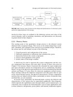
Figure 2.7.5 shows a practical refrigeration cycle on T/s and p/h axes,
assuming a dry vapour enters the compressor.
Fridge plant performance
From the steady flow energy equation, the following expressions
apply,
Refrigeration effect = (h
1
– h
4
) (kJ/kg)
Cooling load =
˙
m(h
1
– h
4
) (kW)
Heat energy to condenser cooling =
˙
m(h
2
– h
3
) (kW)
Work input to compressor = (h
2
– h
1
) (kJ/kg)
Power input to compressor =
˙
m(h
2
– h
1
) (kW)
where
˙
m = mass flow of refrigerant (kg/s)
The coefficient of performance (see page 89, the second law and
coefficient of performance) for the practical cycle is,
COP
ref
=
refrigeration effect
work input
=
h
1
– h
4
h
2
– h
1
Figure 2.7.5 Refrigeration
cycle on T/s and p/h axes
Key points
᭹ There is an increase in
entropy during expansion
and compression.
᭹ There is undercooling in
the condenser, i.e. the
liquid leaving the con-
denser is at a tempera-
ture lower than the
saturation temperature.
᭹ The p/h diagram is partic-
ularly useful for refrigera-
tion plant to show heat
and work energy trans-
fers around the cycle.
Thermodynamics 93
Compressor isentropic efficiency
Figure 2.7.6 shows the h/s diagram for the compression part of the
cycle, in which we can see that if the process is not isentropic, the
enthalpy rise across the compressor is increased, and therefore the work
input is greater.
The compressor isentropic efficiency is given by
T
=
hЈ
2
– h
1
h
2
– h
1
Refrigeration tables.
The theory and nomenclature for the refrigeration tables is the same as
for steam tables. If you have not covered steam, it will be necessary for
you to go over the section on use of the steam tables.
Example 2.7.1
An ammonia refrigerating plant operates between tem-
perature limits of 10.34 bar and 2.265 bar. The refrigerant
leaves the evaporator as a vapour 0.95 dry and leaves the
condenser as a saturated liquid. If the refrigerant mass flow
rate is 4 kg/min, find:
(a) dryness fraction at evaporator inlet;
(b) the cooling load;
(c) volume flow rate entering the compressor.
Figure 2.7.7 shows the plant and Figure 2.7.8 shows the
cycle on T/s and p/h diagrams.
Since the refrigerant leaves the condenser as a saturated
liquid, it must be at saturation temperature and its enthalpy
will be h
f
at 10.34 bar.
Figure 2.7.6 Compressor
isotropic efficiency
Key points
᭹ The layout of the tables is
simplified, and values of
h
fg
are not given in a
separate column and
must be calculated from
h
fg
= h
g
– h
f
.
᭹ Temperature is normally
in the first column and
corresponding saturation
pressure in the second.
᭹ Superheat values at 50K
and 100K only are given.
᭹ Another significant differ-
ence between the tables
is that the entropy and
enthalpy values are given
values of zero at a datum
of –40°C in the refrigera-
tion tables for freon and
ammonia, and 0°C in the
steam tables, for conven-
ience. For refrigerant
134a, the datum is 0°C.
94 Thermodynamics
Using the ammonia tables,
h
3
= 303.7 kJ/kg
The expansion is a constant enthalpy process, i.e. h
3
= h
4
,
303.7 = h
f
+ x.h
fg
at 2.265 bar
303.7 = 107.9 + x(1425.3 – 107.9)
x = 0.149 (a)
The refrigerant leaving the evaporator is wet.
h
1
= h
f
+ x.h
fg
= 107.9 + (0.95 × 1317.4) = 1359.43 kJ
Cooling load =
˙
m(h
1
– h
4
)=
4
60
(1359.43 – 303.7)
= 70.38 kW (b)
The specific volume of the refrigerant at compressor inlet is
v = x.v
g
at 2.265 bar = 0.95 × 0.5296 = 0.50312 m
3
/kg
Volume flow into compressor = mass flow × specific volume
=4 × 0.503 12
= 2.012 m
3
/min (c)
Key point
In this example we do not
need to know the condition
of the vapour after compres-
sion. The diagrams show
that we assume it to be
superheated.
Figure 2.7.7 Example 2.7.1
Figure 2.7.8 Example 2.7.1
Thermodynamics 95
Example 2.7.2
An ammonia vapour-compression refrigeration cycle oper-
ates between saturation temperatures of 20°C and –30°C.
The refrigerant is dry saturated at the compressor inlet and
the compression is isentropic. Find:
(a) the refrigeration effect;
(b) the coefficient of performance.
Figure 2.7.9 shows the plant and Figure 2.7.10 shows the p/h
and T/s axes.
In this case we are given the saturation temperatures. As in
the case of steam, this means that we have the pressures
also, since there can be only one pressure corresponding to
the saturation temperature.
From the ammonia tables.
At – 30°C, p = 1.196 bar
At 20°C, p = 8.57 bar
h
1
= h
g
at 1.196 bar = 1405.6 kJ/kg
s
1
= s
2
= s
g
at 1.196 bar = 5.785 kJ/kgK
h
4
= h
3
= h
f
at 8.57 bar = 275.1 kJ/kg
After compression there is between 50K and 100K of
superheat.
Figure 2.7.9 Example 2.7.2
Figure 2.7.10 Example 2.7.2
96 Thermodynamics
Interpolating using entropy values,
h
2
= 1597.2 +
5.785 – 5.521
5.854 – 5.521
× (1719.3 – 1597.2)
= 1694 kJ/kg
Refrigeration effect = h
1
– h
4
= 1405.6 – 275.1
= 1130.5 kJ/kg (a)
COP =
h
1
– h
4
h
2
– h
1
=
1130.5
1694 – 1405.6
= 3.92 (b)
Example 2.7.3
An ammonia refrigerating plant produces a cooling load of
13.3 kW. The refrigerant leaves the evaporator dry saturated
at 1.902 bar, and leaves the compressor at 7.529 bar, 66°C.
At the exit from the condenser, the temperature of the liquid
refrigerant is 12°C. Find:
(a) the degree of undercooling in the condenser;
(b) the mass flow rate of the refrigerant;
(c) the heat rejected in the condenser in kW;
(d) the compressor power in kW.
See Figures 2.7.11 and 2.7.12.
Figure 2.7.11 Example 2.7.3
Figure 2.7.12 Example 2.7.3
Thermodynamics 97
Using the ammonia tables,
h
1
= h
g
at 1.902 bar = 1420 kJ/kg
h
2
= enthalpy of superheated vapour, since 66 – 16 = 50K
of superheat
h
2
= 1591.7 kJ/kg
At 3, for the pressure of 7.529 bar, the saturation temperature
is 16°C.
We have a temperature of 12°C.
Degree of condenser undercooling = 4K (a)
To find the enthalpy in this case, we can neglect the pressure
and read off the enthalpy at 12°C = 237.2 kJ/kg = h
3
= h
4
.
An alternative is to subtract from the enthalpy at 16°C the
value of 4 × specific heat. (From Q = m.c.␦T.)
Cooling load =
˙
m(h
1
– h
4
) = 13.3
=
˙
m(1420 – 237.2), m = 0.0112 kg/s (b)
Condenser heat rejection =
˙
m(h
2
– h
3
)
= 0.0112(1591.7 – 237.2)
= 15.2 kW (c)
Compressor power = m(h
2
– h
1
)
= 0.0112(1597.1 – 1420)
= 1.98 kW (d)
Example 2.7.4
In a vapour compression refrigeration plant, freon 12 enters
the compressor at a pressure and temperature of 1.826 bar
and –10°C respectively. It is compressed to a pressure and
temperature of 7.449 bar and 45°C respectively. The refriger-
ant leaves the condenser at 25°C. Calculate:
(a) the refrigeration effect;
(b) the compressor work per kg of refrigerant;
(c) the coefficient of performance;
(d) the Carnot coefficient of performance.
See Figures 2.7.13 and 2.7.14.
98 Thermodynamics
Using the freon tables,
h
1
= enthalpy at 1.826 bar with 5K of superheat
h
1
= 180.97 +
5
15
(190.15 – 180.97) = 184.03 kJ/kg
h
4
= h
3
= h
f
at 25°C = 59.7 kJ/kg
Refrigeration effect = h
1
– h
4
= 184.03 – 59.7
= 124.33 kJ/kg (a)
Compressor work = h
2
– h
1
h
2
is 15K of superheat = 210.63 kJ/kg
Compressor work = 210.63 – 184.03 = 26.6 kJ/kg (b)
COP =
h
1
– h
4
h
2
– h
1
=
124.33
26.6
= 4.67 (c)
Carnot COP
ref
=
T
L
T
L
– T
H
=
(–10 + 273)
(45 + 273) – (– 10 + 273)
= 4.78 (d)
Figure 2.7.13 Example 2.7.4
Figure 2.7.14 Example 2.7.5
Thermodynamics 99
Example 2.7.5
In a vapour compression plant, 4.5 kg/min of ammonia leaves
the evaporator dry saturated at a temperature of 2°C and is
compressed to a pressure of 12.37 bar. The isentropic
efficiency of the compressor is 0.85. Assuming no under-
cooling in the condenser, calculate:
(a) the cooling load;
(b) the power input;
(c) the coefficient of performance.
Referring to previous diagrams showing no undercooling in
the condenser and superheat after the compressor,
h
1
= h
f
at 2°C (4.625 bar) = 1446.5 kJ/kg,
h
3
= 332.8 kJ/kg = h
4
s
1
= sЈ
2
= 5.314 kJ/kg K
Cooling load =
˙
m(h
1
– h
4
)=
4.5
60
(1446.5 – 332.8)
= 83.5 kW (a)
Interpolating to find the enthalpy if the compression was
isentropic,
hЈ
2
= 1469.9 +
(5.314 – 4.962)
(5.397 – 4.962)
× (1613 – 1469.9)
= 1585.7 kJ/kg
0.85 =
hЈ
2
– h
1
h
2
– h
1
=
1585.7 – 1446.5
h
2
– 1446.5
, h
2
= 1610.3 kJ/kg
Power = m(h
2
– h
1
)=
4.5
60
(1610.3 – 1446.5)
= 12.29 kW (b)
COP =
cooling load
compressor power
=
83.51
12.29
= 6.8 (c)
100 Thermodynamics
Problems 2.7.1
In each case, sketch the cycle on p/h and T/s axes.
(1) In an ammonia refrigeration plant the refrigerant leaves the
condenser as a liquid at 9.722 bar and 24°C. The evaporator
pressure is 2.077 bar, and the refrigerant circulates at the
rate of 0.028 kg/s. If the cooling load is 25.2 kW, calculate:
(a) the dryness fraction at the evaporator inlet;
(b) the dryness at the evaporator outlet.
(2) A vapour-compression ammonia refrigeration plant operates
between pressures of 2.265 bar and 9.722 bar. The vapour
at the entry to the compressor is dry saturated and there is
no undercooling in the condenser. The coefficient of perform-
ance of the plant is 3.5. Calculate the work input required per
kilogram flow of refrigerant.
(3) A Refrigerant 134a vapour compression cycle operates
between 7.7 bar and 1.064 bar. The temperature of the
refrigerant after the compressor is 40°C and there is no
undercooling in the condenser. If the mass flow rate of the
refrigerant is 0.2 kg/s find the power input to the compressor,
the cooling load, and the coefficient of performance.
(4) A freon refrigerator cycle operates between –15°C and
25°C, and the vapour is dry saturated at the end of
compression. If there is no undercooling in the condenser
and the compression is isentropic, calculate:
(a) the dryness fraction at compressor suction;
(b) the refrigerating effect per kg of refrigerant;
(c) the coefficient of performance;
(d) the Carnot coefficient of performance.
(5) An ammonia refrigeration plant operates between 1.447 bar
and 10.34 bar. The refrigerant enters the throttle as a
saturated liquid and enters the compressor as a saturated
vapour. The compression is isentropic. Calculate the coeffi-
cient of performance of the plant.
(6) A refrigeration plant using Refrigerant 12 operates between
–5°C and 40°C. There is no undercooling in the condenser
and the vapour is dry saturated after isentropic compression.
If the cooling load is 3 kW, calculate:
(a) the coefficient of performance;
(b) the refrigerant mass flow rate;
(c) the power input to the compressor.
(7) A vapour compression refrigerating plant using freon 12
operates between 12.19 bar and 2.61 bar, and the tem-
peratures before and after the compressor are 0°C and 75°C
respectively. The refrigerant leaves the condenser at 40°C.
Calculate:
(a) the isentropic efficiency of the compressor;
(b) the refrigeration effect;
(c) the coefficient of performance.
Thermodynamics 101
(8) An ammonia refrigeration plant operates between 2.265 bar
and 10.34 bar. The ammonia leaves the evaporator at –10°C
and leaves the condenser as a liquid at 26°C. The refrigerant
mass flow rate is 0.4 kg/min and the compressor power
requirement is 1.95 kW. Calculate:
(a) the dryness fraction at the evaporator inlet;
(b) the cooling load;
(c) the coefficient of performance.
2.8 Heat transfer
Heat transfer by conduction is a major consideration in plant such as
boilers and heat exchangers, and through insulation requirements in
buildings. Thermal insulation has important benefits in reducing energy
costs, and in increasing efficiency of plant where heat transfer is
demanded. The purpose of this section is to introduce a practical
approach to the estimate of heat transfer in common situations, by
imparting an understanding of the factors which influence the rate of
heat energy transfer, and applying expressions to calculate heat energy
loss through plane walls and in pipework.
Heat transfer through a plane wall
Figure 2.8.1 shows a plane wall. The rate of heat transfer across the
faces of the wall will depend upon:
᭹ Area of wall, A (m
2
).
᭹ Thermal conductivity of the wall, k (W/m
2
K). As the unit suggests,
this expresses the rate at which heat energy passes through 1 m
2
of
the wall area for each degree K of temperature difference across its
surfaces.
᭹ Thickness of the wall, s (m).
᭹ The temperature difference across the wall, (T
1
– T
2
) (K).
We are dealing here with cases in which the direction of heat energy
flow is perpendicular to the plane surfaces of the wall, and there is no
temperature variation across the surfaces.
For these cases, Fourier’s equation expresses the heat transfer by
conduction as
Q
t
=– k.A.
dt
ds
the negative sign is because the heat energy flow is towards the
direction of temperature fall.
Figure 2.8.1 Heat transfer
through plain wall. Surface
temperatures
102 Thermodynamics
Maths in action
It is necessary to integrate Fourier’s equation to give an
expression for heat transfer into which we can put our
values.
Referring to Figure 2.8.2,
Q
t
= – k.A.
dT
ds
rearranging,
Q
t
ds = – k.A.dT
Integrating both sides,
͵
2
1
Q
t
. ds =
͵
2
1
– k.A.dT
These are definite integrals, i.e. between limits.
Q
t
(s
2
– s
1
)=– k.A (T
2
– T
1
)
Q
t
s = k.A (T
1
– T
2
)
where the wall thickness, (s
2
– s
1
) = s.
Heat transfer between fluids
If we consider the heat transfer rate between, say, two fluids, one either
side of the wall, we must take into account the rate of heat energy lost
from the surface by convection. The type and condition of the surface
(and the velocity of flow over the surface, which we are not considering
here) will influence the rate of convection, which is quantified by a
value of surface heat transfer coefficient, h (W/m
2
K).
By an analysis similar to that for the plane wall we can show that the
heat transfer rate from the surface is given by,
Q
t
= h.A. (T
1
– T
2
)
where (T
1
– T
2
) is the temperature difference between the fluid and the
surface.
We can apply the relevant formula in each case for each part of the
wall.
Figure 2.8.2 Heat transfer
through plain wall. Surface
temperatures
Thermodynamics 103
Referring to Figure 2.8.3 and starting from the left,
for the surface,
Q
t
= h
1
A(T
1
– T
2
), T
1
– T
2
=
Q
t.h
1
.A
for the wall,
Q
t
s = k.A.(T
2
– T
3
), T
2
– T
3
=
Q.s
t.k.A
for the surface,
Q
t
= h
2
.A.(T
3
– T
4
), T
3
– T
4
=
Q
t.h
2
.A
Adding,
(T
1
– T
2
) + (T
2
– T
3
) + (T
3
– T
4
)=
Q
t.h
1
.A
+
Q.s
t.k.A
+
Q
t.h
2
.A
giving,
(T
1
– T
4
)=
Q
A.t
1
h
1
+
s
1
k
+
1
h
2
and, rearranging,
Q =
1
1
h
1
+
s
1
k
+
1
h
2
A.t(T
1
– T
4
)
Students may find it more convenient to use the first equation rather
than the transposed equation.
In Figure 2.8.4 we have a wall consisting of three parts. Taking into
account the surface heat transfer coefficients, and with fluid tem-
peratures T
1
and T
2
, the equations become,
(T
1
– T
2
)=
Q
A.t
1
h
1
+
s
1
k
1
+
s
2
k
2
+
s
3
k
3
+
1
h
2
and,
Q =
1
1
h
1
+
s
1
k
1
+
s
2
k
2
+
s
3
k
3
+
1
h
2
A.t.(T
1
– T
2
)
The value which results from the large bracketed term is the reciprocal
of the overall heat transfer coefficient, U. This is the value which is
often quoted for insulation materials, since it gives a better idea of the
insulation properties than the thermal conductivity alone.
Figure 2.8.3 Heat transfer
through plain wall. Fluid
temperatures
Figure 2.8.4 Heat transfer
through composite wall
Key point
These equations are easily
modified for any configura-
tion by inserting or removing
elements from the large
brackets.
104 Thermodynamics
Exercise 2.8.1
Use reference sources to list values of thermal conductivity,
k, for common materials, and look for overall heat transfer
coefficients, U, for insulation and lagging used in buildings.
Example 2.8.1
A 9.5 mm thick steel plate in a heat exchanger has a thermal
conductivity of 44 W/mK, and the surface temperatures on
either side are 504°C and 204°C. Find the rate of heat
transfer through 1 m
2
of the plate.
Referring to Figure 2.8.5,
T
1
– T
2
=
Q
At
s
k
Note that t is 1 s, because we want the rate of heat energy
transfer, i.e. J/s = W.
(504 – 204) =
Q
1 × 1
0.0095
44
Q =
(504–204) × 1 × 1 × 44
0.0095
= 1 389 474 W = 1389.5 kW
Putting the units into the original equation,
K=
J
m
2
× s
×
m
W
m.K
=
J
m
2
× s
×
m.m.K.s
J
=K
Example 2.8.2
Calculate the heat transfer per hour through a solid brick wall
6 m long, 2.9 m high and 225 mm thick when the outer surface
temperature is 5°C and the inner surface temperature is
17°C, the thermal conductivity of the brick being 0.6 W/mK.
See Figure 2.8.6.
T
1
– T
2
=
Q
At
s
k
(17–5) =
Q
(6 × 2.9) × (60 × 60)
0.225
0.6
Figure 2.8.5 Example 2.8.1
Figure 2.8.6 Example 2.8.2
Thermodynamics 105
Q =
(17 – 5) × (6 × 2.9) × (60 × 60) × 0.6
0.225
= 200 448 J
= 2004.5 kJ
Note that in this case the time is (60 × 60) seconds.
Example 2.8.3
A refrigerated cold room wall has a thickness of 100 mm and
a thermal conductivity of 0.14 W/mK. The room wall has a
60 mm thick internal lining of cork having a thermal con-
ductivity of 0.05 W/mK. The thermal conductance between
the exposed faces and the respective atmospheres is
12 W/m
2
K.
If the room is maintained at 0°C and the external
atmospheric temperature is 20°C, calculate the heat loss rate
through 1 m
2
of the wall.
Figure 2.8.7 shows the wall.
T
1
– T
2
=
Q
A.t
1
h
1
+
s
1
k
1
+
s
2
k
2
+
1
h
2
(20 – 0) =
Q
1 × 1
1
12
+
0.1
0.14
+
0.06
0.05
+
1
12
20 = Q(2.08)
Q = 9.6 W
Example 2.8.4
A cold storage vessel has its outer flat surfaces insulated with
three layers of lagging. The innermost layer is 270 mm thick,
the centre layer is 60 mm thick and the outer layer is 370 mm
thick. The thermal conductivities of the lagging materials are
0.12, 0.1 and 0.2 W/mK respectively. A temperature sensor
embedded half-way through the centre lagging indicates a
temperature of 1°C.
Calculate the temperature of the outer surface of the cold
storage vessel when the outer surface temperature of the
outer layer of lagging is 20°C.
Figure 2.8.8 shows the wall.
This problem demonstrates working through part of the wall
only.
Figure 2.8.7 Example 2.8.3
Figure 2.8.8 Example 2.8.4
106 Thermodynamics
Working from the midpoint of the inner layer, and calling
this temperature T
2
,
T
1
– T
2
=
Q
A.t
s
1
k
1
+
s
2
k
2
20 – 1=
Q
1 × 1
0.37
0.2
+
0.03
0.1
Q = 8.84 W
Remember that Q is the same through all sections of the
wall.
Working from the centre to the inner surface,
T
2
– T
3
=
Q
A.t
s
1
k
1
+
s
2
k
2
1 – T
3
= 8.84
0.03
0.1
+
0.27
0.12
1 – T
3
= 8.84(2.55),
T
3
= –21.54°C
Problems 2.8.1
(1) A brick wall is 3 m high and 5 m wide with a thickness of
150 mm. If the coefficient of thermal conductivity of the brick
is 0.6 W/mK, and the temperatures at the surfaces of the wall
are 25°C and 5°C, find the heat energy loss through the
brickwork in kW.
(2) A cold storage compartment is 4.5 m long by 4 m wide by
2.5 m high. The four walls, ceiling and floor are covered to a
thickness of 150 mm with insulating material which has a
coefficient of thermal conductivity of 5.8 × 10
–2
W/mK.
Calculate the quantity of heat energy leaking through the
insulation per hour when the outside and inside tem-
peratures of the insulation are 15°C and –5°C.
(3) The walls of a cold room are 89 mm thick and are lined
internally with cork of thickness 75 mm. The surface heat
transfer coefficient for both exposed surfaces is 11.5 W/m
2
K.
The external ambient temperature is 22°C and the heat
transfer rate through the wall is 34.5 W/m
2
. Calculate the
temperature inside the cold room.
Thermal conductivity of cork = 0.52 W/mK
Thermal conductivity of wall material = 0.138 W/mK
(4) A cold room wall consists of an inner layer 15 mm thick,
thermal conductivity 0.18 W/mK and an outer layer 150 mm
thick, thermal conductivity 0.045 W/mK. The inside surface
temperature is 0°C and the outside surface temperature is
11°C. Calculate:
Key point
Always make temperature
differences positive.
Thermodynamics 107
(a) the heat transfer rate per unit area of wall;
(b) the interface temperature.
(5) A glass window is to be double-glazed by adding a second
sheet of glass 3 mm thick with an air gap of 20 mm. The
window is 2.3 m high by 1.4 m wide and the original glass is
also 3 mm thick. Basing your calculations on a room
temperature of 23°C and an outside temperature of 2°C, find:
(a) the percentage heat reduction after double-glazing;
(b) the temperature of the outside surface of the outer
glass.
Thermal conductivity of glass = 0.76 W/mK
Thermal conductivity of air = 0.026 W/mK
Inner heat transfer coefficient = 5.7 W/m
2
K
Outer heat transfer coefficient = 9.1 W/m
2
K
Heat transfer through pipe lagging
Figure 2.8.9 shows a pipe with a surface temperature T
1
and a layer of
insulation with surface temperature T
2
. The diameter of the pipe is r
1
and the radius to the outer surface of the lagging is r
2
. The thermal
conductivity of the lagging is k.
Fourier’s equation for this case is
Q
t
= – k.2.r.l.
dT
dr
For length, l, the area of the elemental strip is (circumference × length),
i.e. 2..r.l.
Integrating between 1 and 2 gives,
Q
t
=
2.l.k(T
1
– T
2
)
ln
r
2
r
1
Multi-layer pipe lagging
See Figure 2.8.10.
By the same analysis for a plane wall, and noting that for fluid/
lagging interfaces, the areas are 2.r.l, where r values are for inner pipe
radius and radius to outer layer of lagging,
Q
t
=
2.l(T
1
– T
5
)
1
r
1
.h
i
+
ln
r
2
r
1
k
1
+
ln
r
3
r
2
k
2
+
1
r
3
h
0
This equation looks complicated, but examination will show that it has
a pattern and can be easily adapted to suit any number of elements.
Figure 2.8.9 Heat transfer
through pipe. Surface
temperature
Figure 2.8.10
108 Thermodynamics
As for a plane wall, any element of the pipe can be isolated for
calculating. Across the inner layer for instance,
Q
t
=
(T
2
– T
3
)2.l
ln
r
2
r
1
k
1
Example 2.8.5
A pipe of inner diameter 0.15 m is lagged with 0.065 m thick
material of thermal conductivity 0.6 W/mK. If the inner and
outer surface temperatures of the lagging are 260°C and
50°C respectively, calculate the heat loss per metre length of
pipe.
Figure 2.8.11 shows the pipe.
Using
Q =
2.k.l(T
1
– T
2
)
ln
r
2
r
1
Q =
2.0.6.1(260 – 50)
ln
0.14
0.075
= 1268.72 W = 1.27 kW/m
Example 2.8.6
A steel pipe of 100 mm bore and 10 mm bore thickness,
carrying dry saturated steam at 28 bar, is insulated with a
40 mm layer of moulded insulation. This insulation in turn is
insulated with a 60 mm layer of felt. The atmospheric
temperature is 15°C.
Calculate:
(a) the rate of heat loss by the steam per metre pipe
length;
(b) the temperature of the outside surface.
Inner heat transfer coefficient = 550 W/m
2
K
Outer heat transfer coefficient = 15 W/m
2
K
Thermal conductivity of steel = 50 W/mK
Thermal conductivity of felt = 0.07 W/mK
Thermal conductivity of moulded insulation = 0.09 W/mK
See Figure 2.8.12.
Key point
t is usually 1 s to give Q in W
or kW.
Figure 2.8.11 Example 2.8.5
Thermodynamics 109
t
s
at 28 bar = 230°C
Q =
2.l(T
1
– T
6
)
1
r
1
h
1
+
ln
r
2
r
1
k
1
+
ln
r
3
r
2
k
2
+
ln
r
4
r
3
k
3
+
1
r
4
h
0
(length, l =1)
Q =
2.(230 – 15)
1
0.05 × 550
+
ln
60
50
50
+
ln
100
60
0.09
+
ln
160
100
0.07
+
1
0.16 × 15
Q =
1350.89
0.036 36 + 0.003 646 + 5.6758 + 6.7143 + 0.417
= 105.15 W/m length
To find the outside surface temperature, we work between the
surface and the atmosphere,
Q =
2.(T
5
– T
6
)
1
r
4
.h
0
Q =2.r
4
.h
0
(T
5
– T
6
)
Figure 2.8.12 Example 2.8.6
110 Thermodynamics
the rate of heat transfer is the same through all sections of the
pipe, therefore,
105.15 = 2 × 0.16 × 15(T
5
– T
6
)
(T
5
– T
6
) = 6.97, (T
5
– 15) = 6.97
Surface temperature = T
5
= 21.97°C
Problems 2.8.2
(1) A steam pipe of inner diameter 0.2 m is lagged with 0.08 m
thick material of thermal conductivity 0.05 W/mK. If the inner
and outer surface temperatures of the lagging are 300°C and
50°C respectively, calculate the heat loss per metre length of
pipe.
(2) Saturated steam at a pressure of 10 bar passes through a
steel steam main of 50 mm bore and wall thickness 25 mm.
The main is lagged with a 13 mm layer of cork, and the
ambient temperature is 18°C. Calculate:
(a) the heat transfer rate per metre length of pipe;
(b) the interface temperature between steel and cork;
(c) the surface temperature of the steel;
(d) the surface temperature of the cork.
Thermal conductivity of the steel = 52 W/mK
Thermal conductivity of the cork = 0.04 W/mK
Inside surface heat transfer coefficient = 15 W/m
2
K
Outside surface heat transfer coefficient = 10 W/m
2
K
(3) Fresh water at 65°C flows through a 40 m length of steel pipe
which has a bore of 50 mm and a thickness of 10 mm. The
ambient temperature of the air is 20°C. A 30 mm layer of
insulation is added to the pipe. Calculate the reduction in
heat transfer rate resulting from the addition of the
insulation.
Thermal conductivity of the steel = 52 W/mK
Thermal conductivity of the insulation = 0.17 W/mK
Inside surface heat transfer coefficient = 1136 W/m
2
K
Outside surface heat transfer coefficient from the pipe =
13 W/m
2
K
Outside surface heat transfer coefficient from the insula-
tion = 9.7 W/m
2
K
(4) A steel pipe with an internal diameter of 100 mm and a wall
thickness of 10 mm, carries dry saturated steam at 8 bar, and
is covered with a 12.5 mm thickness of cork. A layer of
moulded polystyrene, with an outer surface temperature of
26°C, covers the cork. The heat loss from the pipe is
100 W/m length. Calculate:
(a) the thickness of the moulded polystyrene;
(b) the outside temperature of the steel pipe.
Key point
When taking log
e
, values can
be radii or diameters, mm
or m.
Thermodynamics 111
Thermal conductivity of the polystyrene = 0.01 W/mK
Thermal conductivity of the steel = 450 W/mK
Thermal conductivity of the cork = 0.04 W/mK
Inside surface heat transfer coefficient = 15 W/m
2
K
(5) A steam pipe, 80 m long, is lagged with two different
materials, each of thickness 50 mm, and carries dry sat-
urated steam which enters the pipe at 12 bar at a rate of
540 kg/h. The pipe is 120 mm diameter with a wall thickness
of 10 mm, and the inner heat transfer coefficient is negligible.
If the ambient temperature is 16.5°C, calculate:
(a) heat loss from the pipe per hour;
(b) dryness fraction of steam at the pipe exit;
(c) interface temperature between the two layers of
insulation.
Coefficient of thermal conductivity of the pipe = 55 W/mK
Coefficient of thermal conductivity of the inner lagging =
0.075 W/mK
Coefficient of thermal conductivity of the outer lagging =
0.15 W/mK
Outer heat transfer coefficient = 12 W/m
2
K
3 Fluid mechanics
Summary
Fluid mechanics is the study of the behaviour of liquids and gases, and particularly the forces that
they produce. Many scientific disciplines have an interest in fluid mechanics. For example,
meteorologists try to predict the motion of the fluid atmosphere swirling around the planet so that
they can forecast the weather. Physicists study the flow of extremely high temperature gases
through magnetic fields in a search for an acceptable method of harnessing the energy of nuclear
fusion reactions. Engineers are interested in fluid mechanics because of the forces that are
produced by fluids and which can be used for practical purposes. Some of the well-known
examples are jet propulsion, aerofoil design, wind turbines and hydraulic brakes, but there are
also applications which receive less attention such as the design of mechanical heart valves.
The purpose of this chapter is to teach you the fundamentals of engineering fluid mechanics
in a very general manner so that you can understand the way that forces are produced and
transmitted by fluids that are, first, essentially at rest and, second, in motion. This will allow you
to apply the physical principles behind some of the most common applications of fluid mechanics
in engineering. Most of these principles should be familiar – conservation of energy, Newton’s
laws of motion – and so the chapter concentrates on their application to liquids.
Objectives
By the end of this chapter, the reader should be able to:
᭹ recognize some fluid properties and types of flow;
᭹ understand the transmission of pressure in liquids and its application to hydraulics;
᭹ use manometry to calculate pressures;
᭹ calculate hydrostatic forces on plane and curved submerged surfaces;
᭹ understand Archimedes’ principle and buoyancy;
᭹ employ the concept of continuity of flow;
᭹ define viscosity;
᭹ calculate pressure drops in pipe flow;
᭹ use Bernoulli’s equation to measure flow rate and velocity;
᭹ apply the momentum principle to liquids in jets and pipes.
Fluid mechanics 113
3.1 Hydrostatics
– fluids at rest
The first half of this chapter is devoted to hydrostatics, the study of
fluids at rest. It is a subject that is most commonly associated with civil
engineers because of their interest in dams and reservoirs, but it is
necessary for mechanical engineers too as it leads on to the subject of
hydrodynamics, fluids in motion.
What are fluids?
Fluids are any substances which can flow. We normally think of fluids
as either liquids or gases, but there are also cases where solids such as
fine powders can behave as fluids. For example, much of the ground in
Japan is made up of fine ash produced by the many volcanoes which
were active on the islands until quite recently. Earthquakes are still
common there and the buildings run the risk of not only collapsing
during the tremors but also sinking into the ground as the powdery ash
deposits turn into a sort of fluid due to the vibration. Nevertheless we
shall only consider liquids and gases for simplicity, and most of the time
we shall narrow the study down even further to liquids because we can
look at the basic principles without the complications that apply to gases
because of their compressibility. There are only a few major differences
between liquids and gases, so let us have a look at them first.
Liquids and gases
It is easiest if we arrange the differences between liquids and gases as
a double list (see Figures 3.1.1–3.1.6).
Liquids Gases
Figure 3.1.1 Liquids have a
fixed volume
Figure 3.1.2 Gases expand to
fill the container
Figure 3.1.3 Liquids are difficult
to compress
Figure 3.1.4 Gases are highly
compressible
h
A
114 Fluid mechanics
From this list of differences it is plain to see that it is much easier to study
liquids, and so that is what we shall do most of the time since the basic
principles of fluid mechanics apply equally well to liquids and gases.
There is only one instance where liquids are more complicated to study
than gases and that is to do with the fact that liquids are much more dense.
Pressure in liquids
The drawback to this approach of concentrating on liquids is that liquids
are very dense compared with gases and so we do not have to go very
far down into a liquid before the pressure builds up enormously due to
the weight of all the mass of liquid above us. This variation of pressure
with depth is almost insignificant in gases. If you were to climb to the
top of any mountain in the UK then you would not notice any difference
in air pressure even though your altitude may have increased by about
1000 metres. In a liquid, however, the difference in pressure is very
noticeable in just a few metres of height (or depth) difference. Anyone
who has ever tried to swim down to the bottom of a swimming pool will
have noticed the pressure building up on the ears after just a couple of
metres. This phenomenon is, of course, caused by gravity which makes
the water at the top of the swimming pool press down on the water
below, which in turn presses down even harder on the ears. In order to
quantify this increase of pressure with depth we need to look at the force
balance on a submerged surface, so let us make that surface an ear drum,
as shown in Figure 3.1.7
Figure 3.1.5 Liquids are not
affected by temperature
Figure 3.1.6 Gases are very
temperature dependent
Figure 3.1.7 Water creating a
pressure on an ear drum
Fluid mechanics 115
We are dealing with gravitational forces, which always act vertically,
and so we only need to consider the effect of any liquid, in this case
water, which is vertically above the ear drum. Water which is to either
side of the vertical column drawn in the diagram will not have any effect
on the pressure on the ear drum, it will only pressurize the cheek or the
neck, etc.
The volume of water which is pressing down on the ear drum is the
volume of a cylinder of height h, equal to the depth of the ear, and end
area A, equal to the area of the ear drum,
Volume = hA
Therefore the mass of water involved is
Volume × density = hA where is the density in kg/m
3
and the weight of this water is
Mass × gravity = ghA
We are interested in the pressure p rather than this force, so that we can
apply the result to any shaped surface. This pressure will be uniform
across the whole of the area of the ear drum and we can therefore
rewrite the force due to the water as pressure × area. Hence:
pA = ghA
Cancelling the areas we end up with:
p = gh (3.1.1)
Since the area of the eardrum cancelled out, this result is not specific to
the situation we looked at; this equation applies to any point in any
liquid. We can therefore apply this formula to calculate the pressure at
a given depth in any liquid in an engineering situation. There are two
further important features that need to be stressed:
᭹ Two points at the same depth in the same liquid must be at the same
pressure even if one of them is not directly underneath the full depth
(Figure 3.1.8).
Figure 3.1.8 Pressure at a
constant overall depth is
constant
116 Fluid mechanics
᭹ The same pressure due to depth can be achieved with a variety of
different shaped columns of a liquid since only the vertical depth
matters (Figure 3.1.9).
Pressure head
We can relate a liquid’s pressure to the height of a column of that liquid
whether there really is a column there or not. We could be producing the
pressure with a pump, for example, but it can still be useful to talk in
terms of a height of liquid since this is a simple measurement which is
easier to understand and visualize than the correct units of pressure
(pascals or N/m
2
). This height can be calculated by rearranging
Equation (3.1.1) to give
h = p/g
and it is known as the pressure head or the static head (since it refers
to liquids at rest). The idea of ‘head’ comes from the early British
engineers who built canals and reservoirs, and realized that the amount
of pressure or even power they could get from the water depended on
the vertical height difference between the reservoir surface and the place
where they were working. The idea was taken up by the steam engineers
of the Victorian era who talked about the ‘head of steam’ they could
produce in a boiler, and it is such a useful concept that it is still used
today even though it sounds old fashioned.
In order to get a better understanding of the meaning of a head, and
to gain practice in converting from head to pressure, we shall now look
at ways of using the height of a column of liquid to measure
pressure.
Manometry
Manometry is the measurement of pressure using columns of liquid,
although more modern electronic pressure measurement devices often
also get called manometers. Liquid manometers are still widely used for
pressure measurement and so this study is far from being of just
historical interest. They are used in a great many configurations, so the
four examples we shall look at here are just illustrations of how to go
about calculating the conversions from a height of liquid in metres to a
pressure in pascals.
Figure 3.1.9 Pressure only
depends on vertical depth