Environmental Forensics: Principles and Applications - Chapter 1 docx
Bạn đang xem bản rút gọn của tài liệu. Xem và tải ngay bản đầy đủ của tài liệu tại đây (639.19 KB, 60 trang )
Library of Congress Cataloging-in-Publication Data
Morrison, Robert D.
Environmental forensics : principles and applications / by Robert
D. Morrison
p. cm.
Includes bibliographical references and index.
ISBN 0-8493-2058-5 (alk. paper)
1. Environmental forensics. 2. Solvents — Environmental aspects.
3. Organochlorine compounds — Environmental aspects. 4. Petroleum
chemicals — Environmental aspects. 5. Hydrocarbons — Environmental
aspects. 6. Groundwater flow. I. Title.
TD193.4.M67 1999
628.5—dc21 99-40624
CIP
This book contains information obtained from authentic and highly regarded sources. Reprinted
material is quoted with permission, and sources are indicated. A wide variety of references are listed.
Reasonable efforts have been made to publish reliable data and information, but the author and the
publisher cannot assume responsibility for the validity of all materials or for the consequences of their use.
Neither this book nor any part may be reproduced or transmitted in any form or by any means,
electronic or mechanical, including photocopying, microfilming, and recording, or by any information
storage or retrieval system, without prior permission in writing from the publisher.
The consent of CRC Press LLC does not extend to copying for general distribution, for promotion, for
creating new works, or for resale. Specific permission must be obtained in writing from CRC Press LLC
for such copying.
Direct all inquiries to CRC Press LLC, 2000 Corporate Blvd., N.W., Boca Raton, Florida 33431.
Trademark Notice: Product or corporate names may be trademarks or registered trademarks and are
used for identification and explanation, without intent to infringe.
© 2000 by CRC Press LLC
No claim to original U.S. Government works
International Standard Book Number 0-8493-2058-5
Library of Congress Card Number 99-40624
Printed in the United States of America 1 2 3 4 5 6 7 8 9 0
Printed on acid-free paper
Preface
Environmental forensics is the systematic examination of environmental information
used in litigation. The purpose of this book is to provide a working reference for the
practicing environmental attorney or environmental consultant. As a working refer-
ence, the topics and examples selected are common denominator issues encountered
in environmental litigation; as such, this book is not intended to be a treatise on a
particular subject but rather to present information that you will likely encounter.
Whenever possible, expanded mathematical or chemical discussions were relegated
to the Appendices.
Chapters 1 and 2 provide a working overview of information about chlorinated
solvents and petroleum hydrocarbons. The foundational information in Chapters 1
and 2 was selected to assist you in deciding which forensic tools described in Chapter
4 are applicable to your case. Recognize that the forensic tools described in Chapter
4 are rapidly evolving. Whenever possible, contact the proponents of these technolo-
gies directly to ascertain their current capabilities relative to your case. Chapters 3
and 5 provide information on how to identify biased environmental data and sugges-
tions in regard to the applications and review of biased environmental data, as well
as suggestions concerning the evaluation of contaminant transport models. Chapter
6 describes techniques for forensically evaluating settlement and trial exhibits and
animations.
The information in this book is intended to allow you to distinguish between
evidence and opinions based on scientific methods vs. junk science. Regardless of
your position on an allegation, everyone is well served if valid technical information
and interpretations form the basis for an expert witness opinion.
Best wishes for a successful and informed environmental career.
Robert D. Morrison
San Diego, CA
©2000 CRC Press LLC
The Author
Robert Daniel Morrison has a B.S. in Geology, an
M.S. in Environmental Studies, an M.S. in Environ-
mental Engineering, and a Ph.D. in Soil Physics from
the University of Wisconsin at Madison. Dr. Morrison
has been working for 27 years in the environmental
field on issues related to soil and groundwater con-
tamination. He specializes in the forensic review and
interpretation of scientific data used in support of
litigation involving soil and groundwater contamina-
tion. Dr. Morrison has published articles and books
on soil and groundwater contamination topics and has
shared this information via lectures throughout the
world. He is active in reviewing technical papers on forensics techniques and has
served on the editorial boards of Ground Water and Groundwater Monitoring
Review and Remediation and currently serves on the editorial board of The Interna-
tional Journal of Environmental Forensics. Dr. Morrison has worked as an expert
witness and consultant for the U.S. Department of Justice, the Environmental
Protection Agency (EPA), and numerous law firms on cases where environmental
forensics were used to allocate responsibility. In the capacity as an expert witness
and confidential consultant, Dr. Morrison has provided testimony in numerous
cases, some with claims ranging from tens of thousands of dollars to as much as five
billion dollars.
©2000 CRC Press LLC
Acknowledgments
Scientists who directly assisted in the preparation of this book include Sherri Komelyan,
Kathleen Calsbeck, Jamie Campos, Kevin Vaughn, and Christian Benitez of R.
Morrison & Associates, Inc. Numerous colleagues and researchers provided assis-
tance in the form of communication and information. Special thanks to Dr. Jim
Bruya, of Friedman & Bruya in Seattle, WA; Dr. James Szecsody, of Battelle
Northwest Laboratories in Hanford, WA; Dr. Blayne Hartman, of TEG in Solano
Beach, CA; David Kaminski, of QED in Ann Arbor, MI; Kevin Beneteau, of Golder
Associates, Calgary, Alberta, Canada; Dr. Barbara Sherwood Lollar, Department of
Geology, University of Toronto, Canada; Dawn Zemo, of Geomatrix in San Fran-
cisco, CA; and Dr. Ramona Aravena, University of Waterloo, Waterloo, Ontario,
Canada.
Special thanks to the wonderful group at CRC Press, especially Becky
McEldowney, who provided creative insight and inspiration, and Debrah Goldfarb.
who provided marketing direction. Special thanks, too, to Sarah Nicely Fortener of
Nicely Creative Services in Geneva, IL, for her wonderful editing of this book.
Special acknowledgement to my wife, Donna, who tolerated my night stalking
and the use of her computer during this effort.
©2000 CRC Press LLC
Contents
Chapters 1 through 6
1 An Overview of the History, Chemistry,
and Transport of Chlorinated Solvents
1.1 Introduction
1.2 Chronology and Use of Chlorinated Solvents
1.2.1 Trichloroethylene (TCE)
1.2.2 Tetrachloroethylene (PCE, or Perchloroethylene)
1.2.3 1,1,1-Trichloroethane (1,1,1-TCA,
or Methylchloroform)
1.2.4 Methylene Chloride (Dichloromethane)
1.3 Chemistry and Properties of Chlorinated Solvents
1.3.1 Terminology and Classification
1.3.2 Chemical Structure and Properties
1.3.3 Henry’s Law Constant (K
H
)
1.3.4 Liquid Density
1.3.5 Solubility
1.3.6 Viscosity
1.3.7 Vapor Pressure and Density
1.3.8 Boiling Point and Latent Heat of Vaporization
1.3.9 Octanol/Water Partition Coefficient (K
ow
)
1.3.10 Hydrolysis
1.3.11 Sorption
1.3.12 Biodegradation
1.3.12.1 Anaerobic Degradation
1.3.12.2 Aerobic Degradation
1.4 Transport of Chlorinated Solvents through Soil
1.5 Impact of Cosolvency on Transport through Soil
1.6 Transport of Vapors in Soil
1.7 Transport through the Capillary Fringe
1.8 Transport in Groundwater
1.8.1 Darcy’s Law
1.8.2 Porosity (n
e
)
1.8.3 Permeability (k) and Hydraulic Conductivity (K)
1.8.4 Retardation
1.8.5 Dispersivity
©2000 CRC Press LLC
1.8.6 Free Phase Solvent Transport in Groundwater
1.8.7 Transport in Fractures
1.8.8 Transport in Fractured Porous Media
References
2 Chemistry and Transport of Petroleum Hydrocarbons
2.1 Introduction
2.2 Chemistry of Crude Oil
2.3 Chemistry of Refined Products
2.3.1 Gasoline
2.3.2 Diesel
2.4 Chemical Reactions in the Vadose Zone
2.4.1 Henry’s Law Constant (K
H
)
2.4.2 Liquid Density
2.4.3 Solubility
2.4.4 Viscosity
2.4.5 Vapor Pressure and Vapor Density
2.4.6 Sorption
2.4.7 Retardation
2.4.8 Biodegradation
2.5 Overview of Transport through the Unsaturated (Vadose) Zone
2.5.1 Transport through Soil
2.5.2 Cosolvation and Colloidal Transport
2.5.3 Residual Saturation
2.5.4 Vapor Phase Transport
2.6 Hydrocarbon Interactions at the Capillary Fringe
2.6.1 Hydrocarbon Solubilization from the
Capillary Fringe into Groundwater
2.7 Transport in Groundwater
2.7.1 Rate of Transport
2.7.2 MTBE Transport in Groundwater
2.7.3 Length of a Petroleum Hydrocarbon Plume
2.7.4 Transport in Fractures
References
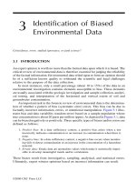
3 Identification of Biased Environmental Data
3.1 Introduction
3.2 Geologic Characterization
3.2.1 Boring Log Terminology
3.3 Interpretation of Geologic Information
3.4 Soil Collection for Chemical Analyses
3.4.1 Soil Sampling Equipment
3.4.2 Subsampling and Sample Transfer
3.4.3 Soil Compositing
©2000 CRC Press LLC
3.5 Groundwater Characterization
3.5.1 Monitoring Well Location
3.5.2 Installation of Groundwater Monitoring Wells
3.5.3 Sampling Plan
3.5.4 Groundwater Purging
3.5.5 Groundwater Sampling
3.5.6 Sampling Equipment and Sequence
3.5.7 Equipment Decontamination
3.5.8 Sample Containers
3.5.9 Sample Filtration, Preservation, and Holding Times
3.5.10 Field Measurements
3.5.11 Field Quality Control Samples
3.6 Soil Vapor Surveys
3.6.1 Interpretation of Soil Vapor Data
3.7 Analytical Methods
3.7.1 Misidentification of Analytes
3.7.2 Laboratory Documentation
3.7.2.1 Chain of Custody
3.7.2.2 Document Control/Control Log
3.7.2.3 Signature List
3.7.2.4 Logbook Cover Sheet
3.7.2.5 Sample Kit Preparation Log
3.7.2.6 Field Logs
3.7.2.7 Sample Receipt Checklist and/or Log
3.7.2.8 Sample Preparation Logbook
3.7.2.9 Sample Analysis Log
3.7.2.10 Instrument Run Log
3.7.2.11 Instrument Maintenance Log
3.7.2.12 Certificates of Analysis
3.7.2.13 Laboratory Certification
3.7.3 Laboratory Quality Control Samples
References
4 Forensic Techniques Used in Environmental Litigation
4.1 Introduction
4.2 Aerial Photography
4.3 Underground Storage Tank Corrosion Models
4.4 Inventory Reconciliation
4.5 Commercial Availability of a Chemical
4.6 Chemicals and Formulations Unique
to a Manufacturing Process or Activity
4.6.1 Polychlorinated Biphenyls
4.7 Petroleum Refinery Throughput Analysis
4.8 Chemical Identification of Petroleum Hydrocarbons
©2000 CRC Press LLC
4.8.1 Analytical Strategy
4.8.2 Proprietary Additives: Petroleum Hydrocarbons
4.8.3 Anti-Knock Additives (Alkyl Leads)
4.8.4 Lead Scavengers
4.8.5 Oxygenates
4.8.6 Trace Inorganics
4.8.7 Petroleum Dyes
4.8.8 Octane Rating
4.9 Radioactive Isotope Dating
4.9.1 Dating Groundwater with Isotopes
4.9.2 Isotopic Analysis for Petroleum Hydrocarbons
4.9.3 Lead Isotope Analysis
4.9.4 Lead Isotope Analysis for Gasoline Fingerprinting
4.9.5 Isotope Analysis of Crude Oil and BTEX
4.9.6 Isotope Analysis of Gas Samples
4.9.7 Isotopic Analysis of Chlorinated Solvents
4.10 Chemical and Biological Degradation Models:
Petroleum Hydrocarbons
4.10.1 Weathering and Biomarkers
4.10.2 Biodegradation Models
4.10.3 Pristane/Phytane Ratios
4.10.4 BTEX Ratios
4.10.5 Challenges to BTEX Ratio Methods
4.11 Chemical Degradation Models: Chlorinated Solvents
4.12 Rapid Optical Screening Tool™ Testing
References
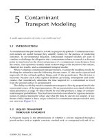
5 Contaminant Transport Modeling
5.1 Introduction
5.2 Liquid Transport through Pavement
5.3 Vapor Transport through Pavement
5.4 Contaminant Transport in Soil
5.4.1 Challenges to Contaminant Transport Models for Soil
5.4.2 Colloidal Transport
5.4.3 Preferential Pathways
5.4.4 Cosolvent Transport
5.5 Contaminant Transport in Groundwater
5.5.1 Types of Groundwater Models
5.5.2 Selection of Boundary Conditions,
Grids, and Mass Loading Rates
5.5.3 Software Applicability
5.6 Application of Groundwater Modeling
in Environmental Litigation
5.6.1 Confirmation Models
©2000 CRC Press LLC
5.6.2 Reverse Models
5.6.3 Hydrogeologic Variables
5.6.4 Contaminant Properties
5.6.5 Challenges to Reverse Models
5.6.6 Challenges to Phase-Separate Reverse Models
References
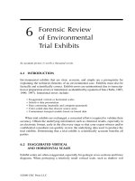
6 Forensic Review of Environmental Trial Exhibits
6.1 Introduction
6.2 Exaggerated Vertical and Horizontal Scales
6.3 Selective Data Presentation
6.4 Data Contouring
6.4.1 Manual Contouring
6.4.2 Computer Contouring
6.4.2.1 Inverse Distance Method
6.4.2.2 Kriging
6.4.2.3 Minimum Curvature Method
6.4.2.4 Sheppard’s Method
6.4.2.5 Polynomial Regression
6.4.3 Color-Coded Data
References
Appendices
A Sample Calculation for the Transport of
PCE Vapor through Concrete Pavement
A.1 Introduction
A.2 Sample Calculation
References
B Sample Calculation for the Transport of
PCE Liquid through Concrete via Diffusion
B.1 Introduction
B.2 Sample Calculation
References
CProperties of Alcohol Oxygenates and Ether Oxygenates
D Advective and Partitioning Transport Equations
of Radon for Detecting Diesel in Groundwater
D.1 Introduction
D.2 Derivation
D.3 Conclusions
References
©2000 CRC Press LLC
E Chemical and Commercial Synonyms for Selected
Chlorinated Solvents and Aromatic Hydrocarbons
References
F Laboratory Terms and Definitions
©2000 CRC Press LLC
Chapters 1 through 6
1
An Overview of the
History, Chemistry,
and Transport of
Chlorinated Solvents
PCE formulated by Faraday in 1821.
1.1 INTRODUCTION
Chlorinated solvents are one of the most frequently encountered contaminants in
environmental investigations (Siegrist, 1993). Trichloroethylene (TCE) and tetra-
chloroethylene (PCE), for example, were detected in 945 groundwater-supplied
drinking systems in an Environmental Protection Agency survey of drinking wells in
the United States. In September 1997, TCE and PCE were detected at 852 and 771,
respectively, of the 1420 National Priority List (NPL) or Superfund sites in the
United States (Butler and Hayes, 1999). As a result of the frequency of detection and
toxicity of chlorinated solvents, millions and often billions of dollars are alleged in
litigation associated with their investigation and remediation.
1.2 CHRONOLOGY AND USE OF
CHLORINATED SOLVENTS
The global production and use of chlorinated solvents began after World War II, with
volumes gradually increasing through the 1950s and 1960s. In the early years of
solvent use, the military was the primary consumer. From 1978 through 1988, the
total production of chlorinated solvents in the United States declined modestly, by
about 11%. After 1988, the decline was more substantial, amounting to about 45%
between 1978 and 1985. The decrease in the demand of chlorinated solvents during
1978 to 1985 reflects the production ban on 1,1,1-trichloroethane (1,1,1-TCA, or
TCA) and Freon-113 (1,1,2-trichloro-1,2,2-trifluoroethane). Another factor in this
decrease was the increased regulations on TCA, tetrachloroethylene (PCE), and
©2000 CRC Press LLC
methylene chloride (MC). The total global capacity for chlorinated solvents in 1994
was about 1.7 million metric tons, with the U.S. accounting for about 36% of the
total, followed by Western Europe and Japan at 40% and 23%, respectively. Table
1.1 summarizes the consumption of chlorinated solvent use in the U.S. in 1988 for
various industries and applications (IRTA, 1994).
The primary use of chlorinated solvents is vapor degreasing. In vapor degreasing,
solvents are boiled (150 to 250∞F), thereby producing a heated vapor zone within the
degreaser. A single-chamber vapor degreaser contains heating coils at the bottom to
boil the liquid solvent, and cooling coils surround the top to contain the vapor (see
Figure 1.1). Metal parts are lowered into the solvent vapor zone for cleaning, usually
in a metal basket. The warm solvent condenses on the colder parts, dissolving the
contaminants or oil into the solvent. In some instances, a spray wand is manually
used to spray the solvent vapor on the parts in the basket. The vapor zone height is
limited by the cooling coils that condense the solvents and return them to the liquid
at the bottom of the degreaser. The mixture drains to a water/solvent separator, where
the heavier solvent sinks to the bottom and the condensed water and dissolved solvent
are disposed. While many vapor degreasers are more sophisticated, with vacuum
TABLE 1.1
Chlorinated Solvent Uses in the U.S. in 1988
Application TCE
a
PCE
b
MC
c
TCA
d
Freon-113
e
Total
Vapor degreasing 47.1 18.1 5.8 106.0 17.7 194.7
Drycleaning — 120.0 — — 2.0 122.0
Intermediate 7.0 80.0 — 22.5 5.3 114.6
Cold cleaning 14.1 6.7 17.2 17.0 40.2 90.2
Electronics 3.2 1.3 16.9 40.8 0.6 78.6
Aerosols — 3.0 20.0 40.8 0.6 64.4
Paint stripping — — 50.0 — — 50.0
Adhesives — — 5.0 26.0 — 31.0
Coatings — 7.0 — 17.2 — 24.2
Flexible foam — — 23.2 — — 23.2
Pharmaceuticals — — 14.4 — — 14.4
Textiles 1.0 2.0 — 7.0 0.5 10.5
Food processing — — 4.2 — — 4.2
Pesticides — — 1.0 3.0 — 4.0
Other — 20.0 49.3 10.5 7.5 87.3
Total demand 72 258 207 298 78 913
Production 82 226 229 328 78 943
a
TCE = trichloroethylene.
b
PCE = tetrachloroethylene.
c
MC = methylene chloride.
d
TCA = 1,1,1-trichloroethane.
e
Freon-113 = trichlorotrifluoroethane.
©2000 CRC Press LLC
systems, multiple chambers, attached distillation units for removing the soils from
the solvent, ultrasonics, and mechanized basket trays, the general operating principle
is the same.
Cold cleaning is another degreasing technique. Cold cleaning is similar to vapor
degreasing, except that the solvent is maintained at room temperature or is heated to
a temperature below the solvent’s boiling point. Like vapor degreasing, metal parts
are dipped into the liquid solvent, and the contaminants are dissolved and removed
from the metal. Cold cleaning is less effective than vapor degreasing because the
solvent is not boiled clean. The heated solvent used in vapor degreasing is also more
effective in degreasing than the same solvent used at room temperature for the same
purpose. The dominant cold cleaning solvent is 1,1,1-TCA.
Equipment related to vapor degreasers includes distillation or evaporation stills
used to recover solvents. The two types of stills are batch and continuous. In a batch
still (also differential, Raleigh, or pot distillation), a fixed amount of spent solvent is
placed inside a heated evaporation chamber from which the condensed vapor is
withdrawn. Continuous, multistage distillation (also fractional distillation) is used
when there is a need for a high degree of distillation purity, if the amount of spent
solvent to be recovered is large, or when differences in solvent volatility are small.
Continuous distillation is accomplished in a column equipped with trays or packing
materials to facilitate contact between the liquid and vapor phases. Liquid is intro-
duced continuously into the column at the top while the vapor moves upward,
becoming more enriched with the more volatile compounds. The high boiling com-
pounds thereby become concentrated in the liquid.
FIGURE 1.1 Single-stage vapor degreaser.
©2000 CRC Press LLC
Knowledge of the vapor degreaser or solvent still manufacturer is useful in
identifying what solvents are compatible with the equipment. Obtaining the original
operating manual from the manufacturer will provide this information. Table 1.2
summarizes the boiling range and types of solvents that can be recycled for several
distillation stills (California Department of Health Services, 1988).
Chlorinated solvents are used in the electronics manufacturing industry, espe-
cially in the production of semiconductors. Applications include:
• Semiconductor wafer fabrication and assembly
• Printed circuit board fabrication and assembly
• In situ generation of etchants
• Miscellaneous critical electronic applications
Chlorinated solvents used in the semiconductor industry include 1,1,2-trichloro-
1,2,2-trifluoroethane (Freon-113); 1,1,1-trichloroethane (TCA); methylene chloride
(MC); trichloroethene (TCE); and tetrachloroethylene (PCE). Freon-113 and TCA
applications include removal of flux from printed circuit boards after the various
electronic components are soldered to the board. TCA is frequently combined with
alcohol because alcohol is an effective flux remover. TCA and methylene chloride
are also used in the photoresist process. In the early 1990s, all photoresist solutions
were solvent, aqueous, or semi-aqueous solutions. In the photoresist process, dry-
film photoresist is applied to the copper substrate of the electronic board and the
desired circuitry is imprinted by shining a high-intensity light through a photomask.
If a negative photoresist is used, the areas of the film exposed to the light polymerize,
whereas the unexposed areas do not. After the developer carries away the
unpolymerized material, the photoresist is then developed with a solvent such as
TCA, which is followed by the etching step. The remaining photoresist is then
stripped, often with methylene chloride. Table 1.3 lists the composition of formulations
TABLE 1.2
Solvent Compatibility with Distillation Stills
Boiling Range
Distillation Model/Manufacturer (∞F) Solvents Recycled
SD-15 Acra Electric; Schiller Park, IL N/A TCE, 1,1,1-TCA, PCE
LS-JR Finish Engineering; Erie, PA 100–320 Alcohols, aromatics, chlorinated
solvents, aliphatics, ketones
ER8; Westport, MA <300 Chlorinated solvents
RS-20 Recyclene Products; San Francisco, CA <400 Methylene chloride, acetone,
methanol, 1,1,1-TCA,
n-butyl-acetate, xylene,
mineral spirits, isopropyl
alcohol, Stoddard solvents
©2000 CRC Press LLC
associated with the photoresist process (California Department of Health Services,
1988).
Wafer fabrication is an integral process of semiconductor manufacturing. Poten-
tial contaminants associated with this process include xylene, n-butyl acetate, ammo-
nium fluoride, hydrofluoric acid, sulfuric acid, arsenic, antimony, copper, zinc,
phosphorus, boron, nitric acid, acetic acid, chromic acid, and phosphoric acid.
Dopants used to change the electrical properties of the silicon wafer include anti-
mony, arsenic, boron, and aluminum. In some cases, the chronological use of dopants
provides a means of determining the earliest date that contaminants with these
compounds were introduced into the environment. A diagram of a wafer fabrication
process used since 1986 is shown in Figure 1.2.
While the use and application of chlorinated solvents for semiconductor manu-
facturing has evolved with time, the manufacturing processes remains similar. The
volume of solvents for different electronic applications in the U.S. for 1987 and 1989
is shown on Table 1.4 (California Department of Toxic Substance Control, 1991). As
shown in Table 1.4, about 72,000 metric tons of chlorinated solvents were used in
1987. Freon-113 was widely used in 1987, followed by TCA and methylene chloride.
The use of TCA and PCE during this time frame is believed to be associated with
degreasing applications. Of the electronic board manufacturing activities, solvent use
was highest for board assembly.
In environmental litigation, the most commonly encountered solvents are TCE,
PCE, 1,1,1-TCA, and methylene chloride. Information about the specific applica-
tions and historical production of these solvents is summarized in the following
sections.
TABLE 1.3
Compounds Associated with the Photoresist Process in Wafer Fabrication
Proprietary Compound Composition
Waycoat photoresist 85% xylene
Microresist developer 95–100% Stoddard solvent
Photoresist developer I 10–30% aromatic hydrocarbons; >60% aliphatic hydrocarbons
Photoresist developer II Mixture of petroleum solvents
Negative photoresist 48% 2-ethoxyethylacetate; 5% n-butyl acetate; 5% xylene.
Positive photoresist 52% 2-ethoxyethylacetate; 6% n-butyl acetate; 6% xylene.
Ultrasonic degreaser Perfluoroisobutylene
Stripper 712D Dodecyl benzene sulfonic acid; 1,2,4-trichlorobenzene, phenols;
pH = 2.4–2.6
Negative photoresist stripper 63% methylene chloride and chlorobenzenes; 23% phenyl sulfonic
J100 (Kodak) acid; 14% phenols and derivatives.
Microstrip 75% chlorinated solvents; orthocresol, dodecylbenzosulfonic acid,
PCE, and dichlorobenzene
Burmar <25% phenol; <25% sulfonic acid; <25% aromatic solvents;
<50% chlorobenzenes
©2000 CRC Press LLC
1.2.1 TRICHLOROETHYLENE (TCE)
Trichloroethylene is used as a metal degreaser and has been available worldwide for
about 50 years. Trichloroethylene was first prepared by Fisher in 1864 during
experiments on the reduction of hexachloroethane with hydrogen (Hardie, 1964).
FIGURE 1.2 Description of processes for semiconductor wafer fabrication, post-1986.
©2000 CRC Press LLC
Trichloroethylene production began in Austria and the United Kingdom in 1908;
Germany, in 1910; the U.S., 1925; and Japan, 1935. Trichloroethylene is manufac-
tured by the catalytic oxidation of 1,1,2,2-tetrachloroethane (U.S. patent number
2,951,103) and the catalytic chlorination of acetylene (U.S. patent number 2,938,931).
In the U.S., the Vietnam War accelerated the use of trichloroethylene for aircraft
parts and engine maintenance and production, cleaning rocket hardware, and space
applications and in the automotive industries. The demand for trichloroethylene in
the U.S. peaked in 1968 at about 261,000 metric tons. In 1970, trichloroethylene
accounted for 82% of all of the chlorinated solvents used in vapor degreasing; in
1976, its share had declined to 42%. By 1975, numerous federal, state, and local
regulations in the U.S. existed that restricted the use of TCE due to its being a
suspected carcinogen. In 1975, the National Cancer Institute reported to the National
Institute of Occupational Safety and Health (NIOSH) that PCE and TCE were
“suspect human carcinogens” and that exposure should be minimized. NIOSH recom-
mended that TCA be handled with caution due to its chemical similarity to PCE and
TCE. In 1976, the U.S. exported about 16 million kg, primarily to the Federal
Republic of Germany (3.8 million kg), France (3.4 million kg), Mexico (2.1 million
kg), and Brazil (2 million kg) (U.S. Department of Commerce, 1977).
The demand for trichloroethylene in the U.S. in 1995 was about 128 million
pounds, of which about 16.5 million pounds were imported and about 40 million
pounds exported (Halogenated Solvents Industry Alliance, 1996). While trichloro-
ethylene is an excellent vapor degreaser due to its ability to degrease faster and more
thoroughly than alkaline cleaners, its suspected carcogenicity resulted in many users
switching to TCA and PCE in the 1970s and 1980s. TCA gradually replaced TCE
from 1963 through 1988; as the demand for trichloroethylene decreased, the use of
TCA increased. In February of 1995, the International Agency for Research on
Cancer (IARC) concluded that there was sufficient epidemiological and animal
TABLE 1.4
Use of Chlorinated Solvents in the Electronic Industry in the U.S.
in 1987 and 1989
1987 (1989)
Applications Freon-113 TCA MC TCE PCE
Wafer fabrication 5.4 0.3 (0.5) 1.3 (0.9) 2.2 (3.0) 0.5 (0.7)
Wafer assembly 2.1 (4.9) 1.1 (2.5) 0.5 (0.8) 0.3 (0.5) (0.3)
Developing photoresist 0.8 (3.2) — — —
Stripping photoresist — — 13.8 (5.0) — —
Defluxing boards 25.6 (23.0) 6.6 (8.0) 0.7 (0.6) 0.5 (0.6) 0.5 (0.6)
Critical cleaning 9.2 (8.3) ————
In situ etchant generation 0.2 (0.2) 0.2 (0.2) — — —
Note: Figures are in units of thousands of metric tons.
©2000 CRC Press LLC
testing data to classify PCE and TCE as “probable human carcinogens”. The IARC
did not classify 1,1,1-TCA as a human carcinogen. In 1996, the applications of TCE
in the U.S. was about 55% for metal cleaning and degreasing, 41% as a chemical
intermediate, and 4% for miscellaneous applications. Water-based products and
compounds such as n-propyl bromide (EnviroChem) became more common as a
replacement for TCE. In the U.S., trichloroethylene is produced by Dow Chemical
Company and PPG Industries.
Global consumption of trichloroethylene decreased from 224,000 metric tons in
1990 to 214,000 in 1993, but there is expected to be an increase in TCE consumption
as a precursor for HFC-134a production. The annual trichloroethylene consumption
in the U.S. and Japan from 1993 to 1998 was expected to increase about 16% and 6%,
respectively. TCE consumption is expected to decrease in Western Europe by about
2% annually, as decreases in the use of TCE in metal degreasing will offset increases
in HFC-134a precursor consumption.
In Western Europe, trichloroethylene is produced by Elf Atochem (France), Dow
Europe/Switzerland (Germany), EniChem (Spain), ICI Chemicals and Polymers
(United Kingdom) and Solvay/Belgium (France and Italy). In Western Europe,
according to the European Chlorinated Solvent Association (1998), TCE production
from 1993 to 1997 was as follows: 1993 and 1994 (94,000 metric tons), 1995
(103,000 metric tons), 1996 (99,000 metric tons), and 1997 (92,000 metric tons). The
increase in TCE production in 1995 and 1996 is due to the replacement of 1,1,1-
trichloroethane with TCE for vapor degreasing.
1.2.2 TETRACHLOROETHYLENE
(PCE, OR PERCHLOROETHYLENE)
Tetrachloroethylene was first formulated in 1821 (Izzo, 1992). Global demand of
PCE decreased from 513,000 metric tons in 1990 to 338,000 metric tons in 1993. The
use of PCE as a precursor in the production of chlorofluorocarbon-113 (CFC-113)
ceased in 1996 due to its association with ozone depletion. In some countries, PCE
consumption is expected to increase due to its use in manufacturing hydrochloro-
fluorocarbon-123 (HCFC-123) and hydrofluorocarbon-134a (HFC-134a). From 1993
to 1998, PCE consumption in the U.S. and Japan increased about 3% but decreased
about 12% annually in Western Europe.
Tetrachloroethylene has been the chlorinated solvent of choice in the drycleaning
industry since the late 1930s. By the late 1940s or early 1950s, PCE replaced
synthetic solvents such as carbon tetrachloride in the drycleaning industry. Prior to
the 1960s, however, petroleum derivatives were still the dominant solvents in the
drycleaning industry in the U.S., where the demand for PCE increased steadily from
1972 to 1981. PCE usage peaked in 1975 at about 348,000 metric tons. After 1975,
a decline in demand continued until 1994, when the demand for tetrachloroethylene
was about 113,000 metric tons. In the late 1980s, drycleaners consumed 56% of the
PCE in the U.S. In 1990, PCE production in the U.S. was about 383 million pounds,
of which 55 million pounds were exported. In 1990, about 72.1 million pounds were
©2000 CRC Press LLC
imported into the U.S. (Halogenated Solvents Industry Alliance, 1994). In the U.S.,
PCE is produced by Dow Chemical USA, PPG Industries, and Vulcan Materials
Company. Figure 1.3 summarizes PCE usage in the U.S. by drycleaners from 1985
to 1997 (Halogenated Solvents Industry Alliance, 1998a). In 1990, tetrachloroethyl-
ene use in the U.S. was 50% for drycleaning/textile processing, 25% as a chemical
intermediate, and 15% in metal cleaning and degreasing, with miscellaneous uses
accounting for about 10% (Halogenated Solvents Industry Alliance, 1998a).
In 1992, there were approximately 34,000 drycleaning businesses in the U.S.,
with about 28,000 facilities using PCE. In 1992, the typical commercial drycleaner
processed about 75,000 pounds of clothing annually, which represented about 90%
of the industry. Approximately 25,000 of these commercial drycleaners used PCE
(about 120,000 metric tons annually) (Wolf, 1992).
The three categories of drycleaning machines that use tetrachloroethylene are
•A transfer machine, in which the clothing is washed in one unit and physically
transferred to a dryer for drying. Emissions from the washer and dryer can be
uncontrolled or they can be routed to a control device. Approximately 30% of all
drycleaning machines are transfer units.
•A dry-to-dry vented unit, in which the clothing is washed and dried in the same
cylinder. The PCE emitted from the unit can be uncontrolled or vented to a control
device. Approximately 70% of the retail drycleaners in the U.S. have dry-to-dry units.
•A dry-to-dry closed loop unit, in which the wash and dry cycles occur in the same
unit. Tetrachloroethylene emissions are controlled within the unit with a refriger-
ated condenser.
FIGURE 1.3 PCE demand by the drycleaning industry in the U.S. from 1985 to 1997.
©2000 CRC Press LLC
Most drycleaners (about 90%) remove soil, dust, hair, and lint from the solvent
with cartridges of activated carbon. Distillation units are used to remove oils and
fats from the solvent. After filtration through the activated carbon or tubular filters,
the solvent is heated to between 190 and 250∞F. The PCE is condensed and
recovered, and the remaining sludge can contain up to 50% PCE. Some drycleaners
reclaim the PCE in the sludge in a muck cooker or a cooker/still combination.
In Western Europe, tetrachloroethylene production declined about 4.8% between
1993 and 1997, from 84,000 tons in 1993 to 68,000 tons in 1997, due to the
replacement of obsolete open drycleaning machines with closed systems. From 1988
to 1998, PCE use in the drycleaning industry in Western Europe declined by about
two thirds due to replacement of older equipment with machines with refrigeration
technology that reduced the volume required for operation (Halogenated Solvents
Industry Alliance, 1998). In Western Europe, TCE is produced by Elf Atochem
(France), Dow Europe/Switzerland (Germany), EniChem (Spain), ICI Chemicals
and Polymers (United Kingdom), and Solvay/Belgium (France and Italy) (European
Chlorinated Solvent Association, 1996).
1.2.3 1,1,1-TRICHLOROETHANE (1,1,1-TCA,
OR METHYLCHLOROFORM)
1,1,1-Trichloroethane was created in 1840 by the reaction of chlorine with 1,1-
dichloroethane. TCA was first reported in the U.S. in 1946 (U.S. Tariff Commis-
sion, 1947). In the U.S., it is produced via the chlorination of vinyl chloride derived
from 1,2-dichloroethane, via hydrochlorination of vinylidene chloride derived from
1,2-dichloroethane, or through the thermal chlorination of ethane. In Japan, 1,1,1-
TCA is produced by the chlorination of vinyl chloride.
TCA production and consumption have decreased dramatically due to its ozone
depletion potential in the upper atmosphere. Global consumption from 1990 to 1993
decreased from 665,000 to 349,000 metric tons. On a worldwide basis, production
was reduced to 50% of its 1989 levels throughout 1994 and 1995. Since 1995, TCA
in Europe has been used only as a precursor chemical. Except for its use as a
precursor, worldwide production essentially ceased in 1996.
TCA is the historical solvent of choice in cold cleaning. The demand for
TCA increased substantially over about three decades (1967 to 1994) in the U.S.
In the late 1960s, when the use of TCE came under scrutiny due to its identifi-
cation as an animal carcinogen, TCA was often used as its replacement. The
historical demand for TCA in the U.S. between 1967 and 1994 peaked in 1988 when
about 298,000 metric tons were consumed. TCA usage declined in 1991 due to an
amendment to the Montreal Protocol that called for a complete phase-out of
TCA by 1996 due to its contribution to ozone depletion. In Western Europe,
most manufacturers ceased production by the end of 1995 with the exception of
its use as a chemical intermediate and for some permitted uses for virgin
solvents. By 1994, the U.S. demand for TCA had decreased to about 159,000
metric tons.
©2000 CRC Press LLC
1.2.4 METHYLENE CHLORIDE (DICHLOROMETHANE)
Methylene chloride was introduced as a replacement for more flammable solvents
over 60 years ago. Total demand in the U.S. in 1996 was about 285 million pounds,
of which about 20 million pounds were imported and about 130 million pounds
exported (Halogenated Solvents Industry Alliance, 1998b). Globally, methylene
chloride is produced by the following manufacturers:
• Aragonesas and Erkimia (Spain)
• Elf Atochem (France)
• Dow Chemical and Vulcan Materials (U.S.)
• Dow Europe/Switzerland (Germany)
• LIL Europe (Germany)
• ICI Chemical and Polymers (United Kingdom)
• Solvay/Belgium (France and Italy)
Methylene chloride consumption in Western Europe decreased from about 190,000
to 135,000 metric tons from 1985 to 1994 (European Chlorinated Solvent Associa-
tion, 1997).
Methylene chloride is the active ingredient in many paint removers, including
commercial and furniture strippers and home paint removers. It is also used in aircraft
maintenance due to its ability to penetrate, blister, and remove a variety of paint
coatings. In the maintenance of military and commercial aircraft, a methylene
chloride-based product is often specified for surface inspection for damage. Since the
mid-1990s, methylene chloride has replaced 1,1,1-TCA in nonflammable adhesive
formulations, including the fabrication of upholstery foam. TCA is currently the
leading auxiliary blowing agent used to produce slabstock flexible polyurethane
foams in the furniture and bedding industries. In the pharmaceutical industry, meth-
ylene chloride is used as a reaction and recrystallization solvent for extraction, as
well as a carrier for pharmaceutical tablet coatings. In the chemical processing
industry, it is used in the production of cellulose triacetate, which serves as a base for
photographic film. The uses of methylene chloride in the U.S. in 1996 and Western
Europe in 1994 as a percentage of the total consumption are shown on Table 1.5
(European Chlorinated Solvent Association, 1997).
1.3 CHEMISTRY AND PROPERTIES
OF CHLORINATED SOLVENTS
1.3.1 T
ERMINOLOGY AND CLASSIFICATION
Chlorinated solvents include a wide range of compounds. As such, a common
terminology for describing these compounds is useful. Acronyms used in environ-
mental reports to characterize chlorinated solvents and non-chlorinated compounds
as a function of their specific density include the following terms (Lizette et al.,
1997):
©2000 CRC Press LLC
• NAPL (non-aqueous phase liquid)
• DNAPL (dense non-aqueous phase liquid)
• LNAPL (light non-aqueous phase liquid)
A NAPL is generally immiscible with water. The term “free phase liquid” is used to
describe a NAPL or DNAPL/LNAPL mixture (U.S. EPA, 1992). A DNAPL describes
a chemical with a fluid density greater than 1.01 g/cm
3
and a vapor pressure less than
300 torr (a torr is equal to 1/760th of a standard atmosphere or about 1 mmHg).
Examples of DNAPLs include acetic acid, phenol, dichloroethylene, carbon disulfide,
naphthalene, polychlorinated biphenyls, ethylene dichloride, sulfuric acid, parathion,
tetrachloroethylene, trichloroethylene, and methyl bromide. LNAPLs are compounds
with a fluid density less than water (about 1.01 g/cm
3
) and include mineral spirits #10,
hexane, gasoline, benzene, butyl acetate, turpentine, ether, crude oil, and diethyl sulfide.
Another classification scheme is based on the degree of halogenation and whether
the compound is volatile or semi-volatile. Classes of chlorinated hydrocarbons based
on this scheme are summarized in Table 1.6. Properties of chlorinated solvents
affecting their fate and transport through the subsurface include their chemical
structure, their Henry’s Law constant, liquid density, water solubility, viscosity,
vapor pressure and density, boiling point, latent heat of vaporization, and the octanol
partition coefficient. Reactions that impact the movement and transformation of
solvents in the subsurface and are interrelated with these chemical and physical
properties include hydrolysis, sorption, and biodegradation.
1.3.2 CHEMICAL STRUCTURE AND PROPERTIES
The major chlorinated solvents used in industry are TCE, PCE, 1,1,1-TCA, the
Freons (primarily chlorofluorocarbon-113, or CFC-113), and methylene chloride.
The chemical structures of these solvents are shown on Figure 1.4. Trichloroethylene
(TCE) and perchloroethylene (PCE) have an ethylene or double-bonded carbon
TABLE 1.5
Use of Methylene Chloride in the U.S. and Western Europe
United States Western Europe
Applications (1996) (1994)
Paint stripping 30 19.14
Adhesives 16 —
Aerosols and coatings 11 11.73
Foam manufacturing 10 —
Pharmaceuticals 10 40.71
Chemical processing 9 8.67
Metal cleaning 8 —
Miscellaneous 6 17.92
Note: Figures are percent of total usage.
©2000 CRC Press LLC
structure with three and four chlorines, respectively. Methylene chloride is a meth-
ylene chlorideane structure containing two chlorine atoms. Trichloroethane (TCA)
and CFC-113 are ethane derivatives. 1,1,1-TCA has three chlorines, all on one
carbon. CFC-113 is fully halogenated with three chlorines and three fluorine atoms.
Freon is a chlorofluorocarbon because it contains a fluorine atom.
TABLE 1.6
Classification of Chlorinated Solvents Based on Degree of
Halogenation and Volatility
Halogenated Volatiles
Chlorobenzene, 1,2-dichloropropane; 1,1-dichloroethylene; 1,2-dichloroethane;
trans-1,2-dichloroethylene; cis-1,2-dichloroethylene; 1,1,1-trichloroethane;
methylene chloride; 1,1,2-trichloroethane; trichloroethylene (TCE); chloroform;
carbon tetrachloride; 1,1,2,2-tetrachloroethane; tetrachloroethylene (PCE);
ethylene dibromide
Halogenated Semi-Volatiles
1,1-dichlorobenzene; 1,2-dichlorobenzene; Aroclor-1242; Aroclor-1254;
Aroclor-1260; chlordane; dieldrin; 2,3,4,6-tetrachlorophenol; pentachlorophenol
Non-Halogenated Semi-Volatiles
2-methyl naphthalene; o-cresol; p-cresol; 2,3-dimethylphenol; m-cresol; phenol;
naphthalene; benzo(a)anthracene; fluorene; acenaphthene; anthracene;
dibenzo(a,h)anthracene; fluoranthene; pyrene; chrysene; 2,4-dinitrophenol
Miscellaneous
Coal tar, creosote
FIGURE 1.4 Chemical structure of PCE, TCE, TCA, Freon-113, and methylene chloride.
©2000 CRC Press LLC