Blueprint Reading - Part 2 (end) potx
Bạn đang xem bản rút gọn của tài liệu. Xem và tải ngay bản đầy đủ của tài liệu tại đây (531.35 KB, 55 trang )
Part II
Schematics
© 2002 by CRC Press LLC
© 2002 by CRC Press LLC
Schematics and
Symbols
INTRODUCTION
Because of the complexity of many electrical and mechanical systems, it would be
almost impossible to show them in full-scale detailed drawing. Instead, symbols and
connecting lines are used to represent the parts of a system.
K
EY
T
ERMS
U
SED
IN
THIS
C
HAPTER
Schematic
is a drawing using symbols and lines.
Symbol
is a simple sign for a device or component.
Fluid
is a liquid or gas.
Legend
is an explanation on some schematics that gives special information
about lines, symbols, and operating characteristics.
Component
is a single unit or part.
Potentiometer
is a three-terminal resistor with an adjustable center connection,
widely used for volume control in radio and television receivers.
12.1 SCHEMATICS
Figure 12.1 shows a voltage divider containing resistance and capacitance connected
in a circuit by means of a switch. Such a series arrangement is called an
RC series
circuit
. Note that, unless the reader is an electrician or electronics technician, it is
not important to understand this circuit. However, it is important to understand that
Figure 12.1 depicts a
schematic
representation formed by the use of symbols and
connecting lines for a technical purpose.
✔
A schematic is a line drawing made for a technical purpose that uses
symbols and connecting lines to show how a system operates.
12.2 HOW TO USE SCHEMATIC DIAGRAMS
Learning to read and use any schematic diagram is a little bit like map reading. In
a schematic for an electrical circuit, for example, it is necessary to know which
wires connect to which component and where each wire starts and finishes. With a
map, this would be equivalent to knowing origin and destination points and which
12
© 2002 by CRC Press LLC
roads connect to the highway network, etc. However, schematics are a little more
complicated, as components need to be identified and some are polarity conscious
(must be wired up in the circuit the correct way) to work. It is not necessary to
understand what the circuit does, or how it works, in order to read it, but it is
necessary to correctly interpret the schematic. Following are some basic rules that
will help with reading a simple diagram (see Figure 12.2).
The heavy lines represent wires and, for simplicity, they have been labeled A,
B, and C. There are just three components here and it is easy to see where each
wire starts and ends, and to which components a wire is connected. As long as the
wire labeled A connects to the switch and negative terminal of the battery, wire B
connects to the switch and lamp, and C connects to the lamp and the battery positive
terminal, this circuit should operate.
Any schematic may be drawn in a number of different ways. For example, in
Figures 12.3 and 12.4 there are two electrically equivalent lamp dimmer circuits
illustrated; they may look very different, but, in fact, if the wires are tracked, it
becomes obvious that, in both diagrams, each wire starts and finishes at the same
FIGURE 12.1
Schematic of an RC series circuit.
FIGURE 12.2
A single schematic diagram.
S1
Charge
current
R
i
d
i
c
E
s
Discharge
current
e
C
e
R
E
S2
C
BC
Switch
+
Battery 6 Volts
A
Lamp
© 2002 by CRC Press LLC
components. The components have been labeled, as have the three terminals of the
transistor (i.e., NPN is the transistor).
In Figure 12.3 there are two wire junctions indicated by a “dot.” A wire connects
from battery positive to the C (transistor collector) terminal, and a wire also runs
from the collector terminal to one end of the potentiometer, VR1. The wires could
be joined at the transistor collector, battery positive or even one end of the potenti-
ometer; it does not matter, as long as both wires exist. Similarly, a wire runs from
battery negative to the lamp, and also from the lamp to the other end of VR1. The
wires could be joined at the negative terminal of the battery, the lamp, or the opposite
leg of VR1. In Figure 12.3, if we had drawn the wires from the lamp and bottom
terminal of VR1 back to the battery negative terminal and placed the dot there, it
would be the same. In Figure 12.4, one wire junction appears at the negative battery
terminal, and the other junction is a similar place.
FIGURE 12.3
Schematic of simple lamp dimmer circuit.
FIGURE 12.4
Schematic of a simple dimmer circuit.
+
12V
b
c
NPN
e
VR1
10k
R1
1k
12V
+
VR1
10K
R1
1k
e c
b
NPN
© 2002 by CRC Press LLC
12.2.1 S
CHEMATIC
C
IRCUIT
L
AYOUT
Sometimes, the way a circuit is wired may compromise its performance. This is
particularly important for high-frequency and radio circuits, and some high-gain
audio circuits.
Consider the audio circuit shown in Figure 12.5. [
Note
: For our purposes, we
have simplified the following explanation.] Although this circuit has a voltage gain
of less than 1, wires to and from the transistor should be kept as short as possible.
This will prevent a long wire picking up radio interference or hum from a transformer.
Moreover, in this circuit, input and output terminals have been labeled and a common
reference point or earth (ground) is indicated. The ground terminal would be con-
nected to the chassis (metal framework of the enclosure) in which circuit is built.
Many schematics contain a chassis or ground point. Generally, it is just to indicate
the common reference terminal of the circuit, but in radio work, the ground symbol
usually requires a physical connection to a cold water pipe or a length of pipe or
earth spike buried in the soil.
12.3 SCHEMATIC SYMBOLS
Water or wastewater operators and maintenance operators must be Jacks or Jills of
many trades. Simply, a good maintenance operator must be able to do many different
kinds of jobs. To become a fully qualified “Jack” or “Jill,” the maintenance operator
must learn to perform many special tasks, including electrical, mechanical, piping,
fluid-power, AC and R, hotwork, etc. Moreover, maintenance operators must be
flexible; they must be able to work on both familiar and new equipment and systems.
Seasoned maintenance operators may state that they can “fix” anything and
everything using nothing more than their own intuition (i.e., seat-of-the-pants
FIGURE 12.5
Schematic of a simple audio circuit.
+
+
+
9V
Q1
BC109C
C1
10u
R1
2.2k
R3
560k
C2
1uF
R2
470k
input
output
© 2002 by CRC Press LLC
troubleshooting). However, in the real world, to troubleshoot systems, maintenance
operators must be able to read and understand schematics. By learning this skill,
operators will have little difficulty understanding, maintaining, and repairing almost
any equipment or unit process in the plant — old or new.
12.3.1 L
INES
ON
A
S
CHEMATIC
As mentioned, symbols are used instead of pictures on schematics. Moreover, as
mentioned, a schematic is a line diagram. Lines on a schematic show the connections
between the symbols (devices) in a system. Each line has meaning; thus, we can
say that schematic lines are part of the symbology employed. The meaning of certain
lines, however, depends on the kind of system the schematic portrays. For example,
a simple solid line can have totally different meanings. On an electrical diagram, it
probably represents wiring. On a fluid-power diagram, it stands for a working line.
On a piping diagram, it could mean a low-pressure steam line. Figure 12.6 shows
some other common lines used in schematics.
A schematic diagram is not necessarily limited to one kind of line. In fact, several
kinds of lines may appear on a single schematic. Following applicable ANSI stan-
dards, most schematics use only one thickness, but they may use various combina-
tions of solid and broken lines.
✔
Not all schematics adhere to standards set by national organizations as an
aid in providing uniform drawings. Some designers prefer to use their
own line symbols. These symbols are usually identified in a legend.
12.3.2 L
INES
C
ONNECT
S
YMBOLS
A diagram filled with lines may simply have nothing more than a diagram filled
with lines. Likewise, a diagram with assorted symbols may simply be a diagram
filled with various symbols. Such diagrams may have meaning to someone, but
probably have little meaning to most. To make a schematic readable (understand-
able), to a wide audience, a diagram must use a combination of recognizable lines
and symbols.
When symbols are combined with lines in schematic form, it is necessary to
also understand the meaning of the symbols used. The meaning of certain symbols
depends on the kind of system the schematic shows. For example, the symbols used
in electrical systems differ from those used in piping and fluid-power systems.
The bottom line: to understand and properly use a schematic diagram, it is
necessary to understand the meaning of both the lines and the symbols used.
12.4 SCHEMATIC DIAGRAM: AN EXAMPLE*
Note that Figure 12.7 shows a schematic diagram used in electronics and com-
munications. The layout of this schematic involves the same principles and
* Adapted from ANSI Y14.15,
Dimensioning and Tolerancing
. New York: American National Standards,
pp. 1–14, 1982.
© 2002 by CRC Press LLC
procedures (except for lesser detail) suggested for more complex schematics.
Although less complex than most schematics, Figure 12.7 serves our intended
purpose: to provide a simplified schematic diagram for basic explanation and easier
understanding of a few key points — essential to understanding schematics and
how to use them.
FIGURE 12.6
Examples of lines used in schematics.
Wire concealed in ceiling or wall
Wiring concealed in floor
Exposed wiring
3 wires
4 wires
Wiring turned up
Wiring turned down
Nonintersecting pipes
Air
Vacuum
Gas
Low-pressure steam
Vent
Condensate
Cold water
Refrigerant liquid
Hot water
Working line Drain line
Pilot line Direction of flow
Electrical
V
Piping
Fluid-power
G
A
RL
© 2002 by CRC Press LLC
12.4.1 A S
CHEMATIC
BY
A
NY
O
THER
N
AME
IS
A
L
INE
D
IAGRAM
The schematic (or line) diagram is intended to describe the basic functions of a
circuit or system. As such, the individual lines connecting the symbols may represent
single conductors or multiple conductors. The emphasis is on the function of each
stage of a device and the composition of the stage.
The various parts or symbols used in a schematic (or line) diagram are typically
arranged to provide a pleasing balance between blank areas and lines (see Figure
12.7). Sufficient blank spaces are provided adjacent to symbols for insertion of
reference designations and notes.
It is standard practice to arrange schematic and line diagrams so that the signal or
transmission path from input to output proceeds from left to right (see Figure 12.7) and
from top to bottom for a diagram in successive layers. Supplementary circuits, such as
a power supply and an oscillator circuit, are usually shown below the main circuit.
Stages
of an electronic device, such as shown in Figure 12.7, are groups of
components, usually associated with a transistor or other semiconductor, which
together perform one function of the device.
Connecting lines
(for conductors) are drawn horizontally or vertically, for the
most part, minimizing bends and crossovers. Typically, long interconnecting lines
are avoided. Instead,
interrupted paths
are used in place of long, awkward intercon-
necting lines or where a diagram occupies more than one sheet. When parallel
connecting lines are drawn close together, the spacing between lines is not less than
.06" after reduction. As a further visual aid, parallel lines are grouped with consid-
eration of function, and with double spacing between groups.
FIGURE 12.7
Single-line diagram. (From ANSI Y14.15
Dimensioning and Tolerancing
. New
York: American National Standards, text, 1982.)
Terminals
for test
loudspeakers
VU
Condition
switch
Busses
Reference
Test
Power
amplifiers
Permanent
loudspeaker
1
2
3
4
Monitor
loudspeaker
Talkback
microphone
RU A
MON
Talkback
channel
© 2002 by CRC Press LLC
Crossovers
are usually necessary in schematic diagrams. The looped crossovers
shown in Figure 12.8A have been used for several years to avoid confusion. However,
this method is not approved by the American National Standard. A simpler practice
recognized by ANSI is shown in Figure 12.8B. Connection of more than three lines
at one point, shown at A, is not recommended and can usually be avoided by moving
or staggering one or more lines as at B.
ANSI Y14.15 (cited earlier) recommends crossovers as shown in Figure 12.8C.
In this system it is understood that termination of a line signifies a connection. If
more than three lines come together, as at C, the dot symbol becomes necessary.
Interrupted paths
, either for a single line or groups of lines, may be used where
desirable for overall simplification of a diagram.
12.5 SCHEMATICS AND TROUBLESHOOTING*
As mentioned, one of the primary purposes of schematic diagrams is to assist the
maintenance operator in troubleshooting system, component or unit process faults.
While it is true that a basic schematic can be the troubleshooter’s best friend,
experience has shown that many mistakes and false starts can be avoided by taking
a step-by-step approach to troubleshooting.
Experienced water or wastewater maintenance operators usually develop a stan-
dard troubleshooting protocol or step-by-step procedure to assist them in their
troubleshooting activities. No single protocol is the same; each troubleshooter pro-
ceeds based on intuition and experience (not on seat-of-the-pants solutions). How-
ever, the simple 15-step protocol (along with an accurate system schematic)
described below has worked well for those who have used it
(Note:
Recognize that
several steps may occur at the same time.)
* Adapted from Spellman, F.R.,
Spellman's Standard Handbook for Wastewater Operators: Volume 3,
Advanced Level
. Lancaster, PA: Technomic Publishing Company, pp. 16–17, 2000.
FIGURE 12.8
Crossovers.
A
B
A
B
C
C
© 2002 by CRC Press LLC
1. Recognize a problem exists (figure out what it is designed to do, and how
it should work).
2. Review all available data.
3. Find the part of the schematic that shows the troubled area, and study it
in detail.
4. Evaluate the current plant operation.
5. Decide what additional information is needed.
6. Collect the additional data.
7. Test the process by making modifications and observing the results.
8. Develop an initial opinion as to the cause of the problem and potential
solutions.
9. Fine tune your opinion.
10. Develop alternative actions to be taken.
11. Prioritize alternatives (i.e., prioritize based on its chances of success, how
much it will cost, etc.).
12. Confirm your opinion.
13. Implement the alternative actions (this step may be repeated several
times).
14. Observe the results of the alternative actions implemented (i.e., observe
impact on effluent quality; impact on individual unit process performance;
changes, or trends, in the results of process control tests and calculations;
impact on operational costs).
15. During project completion, evaluate other, more permanent long-term
solutions to the problem (such as chemical addition, improved preventive
maintenance, design changes, etc.). Continue to monitor results. Docu-
ment the actions taken and the results produced for use in future problems.
SELF-TEST
12.1 Symbols are connected by lines in a ___________ diagram.
12.2 A schematic is made for a(n) _____________ purpose.
12.3 Another name for a schematic diagram is a _________ diagram.
12.4 A schematic is useful because it shows a system in _________ form.
12.5 The three major areas for which schematics are drawn are
_____________, __________, and ___________.
12.6 Interruption of flow within an electronic system is usually indicated by
___________ signs.
12.7 A simple sign for a device: ____________.
12.8 A liquid or gas: ____________.
12.9 Explanation appearing on some schematics that gives special informa-
tion: ____________.
12.10 A well-prepared schematic is drawn with lines connecting the compo-
nent parts in a __________________.
© 2002 by CRC Press LLC
Electrical Schematics
INTRODUCTION
A good deal of the water or wastewater treatment process equipment in use today
runs by electricity. Plants must keep their electrical equipment working. When a
machine fails or a system stops working, the plant maintenance operator must find
the problem and solve it quickly.
No maintenance operator can be expected to remember all the details of a plant’s
electrical equipment. This information must be stored in diagram or drawings, in a
format that can be readily understood by trained and qualified maintenance operators.
Electrical schematics store the information in a user-friendly form.
This chapter describes the basics of electrical schematics and wiring diagrams.
Typical symbols and circuits are used as examples.
K
EY
T
ERMS
U
SED
IN
THIS
C
HAPTER
Ground
is an electrical connection to a metal frame or the earth.
Battery
is two or more cells connected.
Ampere (A)
is the unit of current.
Chassis
is a sheet-metal box, frame or simple plate on which electronic
components and their associated circuitry can be mounted.
Circuit breaker
is a device that opens and closes a circuit by non-automatic
means or that opens the circuit automatically on a predetermined overload
of current, without change to itself when properly applied within its rating.
Disconnect switch
is a switch intended for use in a motor branch circuit.
Schematic diagram
is a diagram in which symbols and a plan of connection
are used to illustrate the scheme of control in simple form.
Fuse
is an overcurrent protection device containing a calibrated current-car-
rying member that melts and opens a circuit under specified over-current
conditions.
Interlock
is a device actuated by the operation of another device with which it
is directly associated. The interlock governs succeeding operations of the
same or allied devices and may be either electrical or mechanical.
Overload relay
is a device that provides overload protection for the electrical
equipment.
Power supply
is the unit that supplies the necessary voltage and current to the
system circuitry.
Symbol
is a widely accepted sign, mark or drawing that represents an electrical
device or component thereof.
13
© 2002 by CRC Press LLC
Volt
(V)
is the unit of electrical pressure or potential.
Watt (W)
is the unit of electrical power pressure or potential.
13.1 ELECTRICAL DRAWINGS
In describing electrical systems, three kinds of drawings are typically used: pictorial,
wiring, and schematic.
Pictorial drawings
show an object or system much as it
would appear in a photograph. Several sides of the object are visible in the one
pictorial view. Pictorial drawings are quite easy to understand. They can be used in
making or servicing simple objects but are usually not adequate for complicated
parts or systems, such as electrical components and systems. A
wiring diagram
shows the connections of an installation or its component devices or parts. It may
cover internal or external connections, or both, and contains such detail as is needed
to make or trace connections that are involved. The wiring diagram usually shows
general physical arrangement of the component devices or parts. A
schematic dia-
gram
uses symbols instead of pictures for the working parts of the circuit. These
symbols are used in an effort to make the diagrams easier to draw and easier to
understand. In this respect, schematic symbols aid the maintenance operator in the
same way that shorthand aids a stenographer.
✔
A schematic diagram emphasizes the flow in a system. It shows how a
circuit functions, rather than how each part actually looks. Stated differ-
ently, a schematic represents the
electrical
, not the physical, situation in
a circuit.
13.2 ELECTRICAL SYMBOLS
Electrical and electronic circuits are indicated by very simple drawings called
sche-
matic symbols
, which are standardized throughout the world with minor variations.
Some of these symbols look like the components they represent. Some look like
key parts of the components they represent. A maintenance operator, must know
these symbols to read the diagrams and keep the plant equipment in working order.
The more schematics are used, the easier it becomes to remember what these symbols
mean.
13.2.1 S
CHEMATIC
L
INES
In electrical and electronic schematics, lines symbolize wires connecting various
components. Different kinds of lines have different meanings in schematic diagrams.
Figure 13.1 shows examples of some lines and their meanings; other lines are usually
identified by a diagram legend.
To understand any schematic diagram, it is necessary to observe how the lines
intersect. These intersections show that two or more wires are connected, or that the
wires pass over or under each other without connecting.
© 2002 by CRC Press LLC
Note, as mentioned, Figure 13.1 shows some of the connections and crossings
of lines. When wires intersect in a connection, a dot is used to indicate this. If it is
clear that the wires connect, the dot is not used.
✔
Wires and how they intersect are important. Maintenance operators must
be able to tell the difference between wires that connect and those that
do not to be able to properly read the schematic and determine the flow
of current in a circuit.
13.2.2 P
OWER
S
UPPLIES
: E
LECTRICAL
S
YSTEMS
*
Most water or wastewater treatment facilities receive electrical power from the
transmission lines of a utility company. On a schematic, the entry of power lines
into the plant’s electrical system can be shown in several ways. Electrical power
supply lines to a motor are shown in Figure 13.2.
Another source of electrical power is a battery. A battery consists of two or more
cells. Each cell is a unit that produces electricity by chemical means. The cells can
be connected together to produce the necessary voltage and current. For example,
a 12-V storage battery might consist of six 2-V cells.
On a schematic, a battery power supply is represented by a symbol. Consider
the symbol in Figure 13.3. The symbol is rather simple and straightforward, but is
also very important. For example, by convention, the shorter line in the symbol for
a battery represents the negative terminal. It is important to remember this, because
it is sometimes necessary to note the direction of current flow, which is from negative
to positive, when you examine the schematic. The battery symbol shown in Figure
13.3 has a single cell, so only one short and one long line are used. The number of
lines used to represent a battery vary (and they are not necessarily equivalent to the
number of cells), but they are always in pairs, with long and short lines alternating.
In the circuit shown in Figure 13.4, the current would flow in a
counterclockwise
direction; that is, in the opposite direction that a clock’s hands move. If the long
FIGURE 13.1
Symbols for wires.
* From Spellman, F.R. and Drinan, J.,
Fundamentals for the Water & Wastewater Maintenance Operator
Series: Electricity.
Lancaster, PA: Technomic Publishing Company, pp. 44-45, 2001.
Single wire
Wiring concealed in floor
Wires crossing but not connected
Wires connected (Dot required)
Exposed wiring
© 2002 by CRC Press LLC
and short lines of the battery symbol (shown in Figure 13.3) were reversed, the
current in the circuit shown in Figure 13.4 would flow
clockwise
; that is, in the
direction of a clock’s hands.
FIGURE 13.2
Electrical power supply lines.
FIGURE 13.3
Schematic symbol for a battery.
FIGURE 13.4
Schematic of a simple fused circuit.
M
L
1
L
2
L
3
+-
Battery
R
Fuse
© 2002 by CRC Press LLC
4 Current flows from the negative (–) terminal of the battery, shown in
Figure 13.4, through the switch, fuse, and resistor (R) to positive (+)
battery terminal, and continues going through the battery from the positive
terminal to the negative terminal. As long as the pathway is unbroken, it
is a closed circuit, and current will flow. However, if the path is broken
(e.g., switch is in open position), it is an open circuit, and no current flows.
4 In Figure 13.4, a fuse is placed directly into the circuit. A fuse will open
the circuit whenever a dangerously large current starts to flow (i.e., a
short-circuit condition occurs, caused by an accidental connection
between two points in a circuit that offer very little resistance). A fuse
will permit currents smaller than the fuse value to flow but will melt and
therefore break or open the circuit if a larger current flows.
In water or wastewater treatment operations, maintenance operators are most
likely to maintain or troubleshoot circuits connected to an outside power source.
However, on occasion, they may also work on some circuits that are battery powered.
In fact, in work on electronics systems, more work may be performed on battery-
power supplied systems than on outside sources. Electronic power supply systems
are discussed in the following section.
13.2.3 P
OWER
S
UPPLIES
: E
LECTRONICS
*
In electronics, power supplies perform two important functions: (1) they provide
electrical power when no other source is available; and (2) they convert available
power into power that can be used by electronic circuits. For example, power supplies
can be used to provide the DC supply voltage needed for an amplifier, oscillator, or
other electronic device.
✔
Conversion from one type of power supply (AC to DC, for example) does
not improve the quality of the input power, so power conditioners are
added for smoothing.
A simple schematic diagram (see Figure 13.5) provides the best way to demon-
strate the actual makeup of an electronic power supply. As shown in the figure, a
basic power supply consists of four sections: a transformer, a rectifier, a smoothing
section, and a load. The transformer converts the 120-V line AC to a lower AC
voltage. The rectifier section is used to convert the AC input to DC. Unfortunately,
the DC produced is not smooth DC but instead is pulsating DC. The smoothing, or
conditioning section, functions to take the pulsating DC and convert it to a pure DC
with as little AC ripple as possible. The smoothed DC is then applied to the load.
Electronic components must have electrical power to operate. This electrical
power is usually direct current (in electronic equipment). Components typically use
* From Spellman, F.R. and Drinan, J.,
Fundamentals for the Water & Wastewater Maintenance Operator
Series: Electricity.
Lancaster, PA: Technomic Publishing Company, pp. 181-184, 2001.
© 2002 by CRC Press LLC
a single low voltage, usually 5 V, and single polarity, either positive (+5V) or negative
(–5V). Circuits often require several voltages and both polarities, typically +5V, –5,
+12V, and –12V.
One of the simplest power supplies, a DC–DC power supply, is shown in
schematic form, depicted in Figure 13.6. In this simple circuit, if the current drawn
by the load does not change, the voltage across the resistor (often referred to as a
dropping resistor
) will be as steady as the source voltage.
In an AC–DC power supply, a
rectifier
, which changes the 60-Hertz AC input
voltage to fluctuating, or pulsating, DC output voltage, is used. The diode allows
current in only one direction, for one polarity of applied voltage. Thus, current flows
in the output circuit only during the half-cycles of the AC input voltage that turn
the diode on.
Figure 13.7 shows a schematic of a typical AC–DC power supply. Notice that
the input is 120-V AC, which is typical of the voltage supplied to most households
and businesses from a utility line. The 120-V AC is fed to the primary of a trans-
former. The transformer reduces the voltage of the AC output from the secondary.
The transformer output (secondary output) is the input to the rectifier, which delivers
a pulsating DC output. The rectified output is the input to the filter, which smoothes
out the pulses from the rectifier. The filter output is the input to the voltage regulator,
which maintains a constant voltage output, even if the power drawn by the load
changes. The voltage regulator output is then fed to the load.
Power smoothers
, or conditioners, are built into or added to power supplies to
regulate and stabilize the power supply. They include filters and voltage regulators.
For example, a
filter
is used in both DC output and AC output power supplies. In
DC output power supplies, filters help smooth out the rectifier output pulses, as
shown in Figure 13.8. In AC output power supplies, filters are used to shape wave-
forms (i.e., they remove the undesired parts of the waveform).
FIGURE 13.5
Basic power supply.
FIGURE 13.6
Schematic of basic DC to AC power supply.
Rectifier
section
Smoothing
section
Transformer
Input
Load
R
1
E in
R
L
E out
© 2002 by CRC Press LLC
13.2.4 E
LECTRICAL
L
OADS
As mentioned, an electric circuit, which provides a complete path for electric current,
includes an energy source (source of voltage, i.e., a battery or utility line), a conductor
(wire), a means of control (switch), and a load. As shown in the schematic repre-
sentation in Figure 13.9, the energy source is a battery. The battery is connected to
the circuit by conductors (wire). The circuit includes a switch for control. The circuit
also consists of a load (resistive component). The
load
that dissipates battery-stored
energy could be a lamp, motor, heater, resistor, or some other device (or devices)
that does useful work, such as an electric toaster, a power drill, radio, or soldering
iron.
Figure 13.10 shows some symbols for common loads and other components in
electrical circuits. The maintenance operator should become familiar with these
symbols (and others not shown here), because they are widely used.
✔
Every complete electrical or electronic circuit has at least one load.
13.2.5 S
WITCHES
In Figures 13.4 and 13.9, the schematics show simple circuits with switches. A
switch
is a device for making or breaking the electrical connection at one point in
a wire. A switch allows the starting, stopping, or changing the direction of current
flow in a circuit. Figure 13.11 shows some common switches and their symbols.
13.2.6 I
NDUCTORS
(C
OILS
)
Simply put, an
inductor
is a coil of wire, usually many turns (of wire) around a
piece of soft iron (magnetic core). In some cases, the wire is wound around a non-
conducting material. Inductors are used as ballasts in fluorescent lamps, and for
magnets and solenoids.
When electric current flows through a coil, it creates a magnetic field (an
electromagnetic field). The magnetism causes certain effects needed in electric
FIGURE 13.7
Schematic of an AC to DC power supply.
FIGURE 13.8
Ripple in filter output.
Load
Transformer
Rectifier
Filter
Voltage
Regulator
Low- voltage
A-C output
Rectified
D-C output
Filtered
D-C output
Regulated
D-C output
120-v A-C
Pulsating D-C Filtered output
Filter
© 2002 by CRC Press LLC
circuits (e.g., in an alarm circuit, the magnetic field in a coil can cause the alarm
bell to ring). It is not important to understand these effects to read schematic
diagrams. It is, however, important to recognize the symbols for inductors (or coils).
These symbols are shown in Figure 13.12.
13.2.7 T
RANSFORMERS
Transformers
are used to increase or decrease AC voltages and currents in circuits.
The operation of transformers is based on the principle of
mutual inductance
. A
transformer usually consists of two coils of wire wound on the same core. The
primary coil is the input coil of the transformer and the secondary coil is the output
coil. Mutual induction causes voltage to be induced in the secondary coil. If the
output voltage of a transformer is greater than the input voltage, it is called a
step-up
FIGURE 13.9
Schematic of a simple closed circuit.
FIGURE 13.10
Symbols for electrical loads.
Conductor (wire)
Load (resistor)
Battery (EMF)
Conductor (wire)
Control switch
or
R
Resistance heating element
Incandescent lamp
M V A R
Motor Voltmeter Ammeter
Relay
© 2002 by CRC Press LLC
transformer. If the output voltage of a transformer is less than the input voltage, it
is called a
step-down
transformer. Figure 13.13 shows some of the basic symbols
that are used to designate transformers on schematic diagrams.
FIGURE 13.11
Types of switches.
FIGURE 13.12
Symbols for coils and inductors.
FIGURE 13.13
Transformer symbols.
Abbreviation
SPST
DPST
SPDT
DPDT
NO
NC
NC-NO
Symbol
Toggle switch Knife switch
Type of switch
Single pole, single throw
Double pole, single throw
Single pole, double throw
Double pole, double throw
Normally open
Normally closed
Two-position
Relay coil
Fixed coil
Solenoid
Tapped coil
Variable coil
or
R
Transformer with
iron core
Transformer
with taps
Autotrans-
former
© 2002 by CRC Press LLC
13.2.8 F
USES
A
fuse
is a device that automatically opens a circuit when the current rises above a
certain limit. When the current becomes too high, part of the fuse melts. Melting
opens the electrical path, stopping the flow of electricity. To restore the flow, the
fuse must be replaced. Figure 13.14 shows some of the basic symbols that are used
to designate fuses on schematic diagrams.
13.2.9 C
IRCUIT
B
REAKERS
A
circuit breaker
is an electric device (similar to a switch) that, like a fuse, interrupts
an electric current in a circuit when the current becomes too high. The advantage
of a circuit breaker is that it can be reset after it has been tripped; a fuse must be
replaced after it has been used once. When a current supplies enough energy to
operate a trigger device in a breaker, a pair of contacts conducting the current are
separated by pre-loaded springs or some similar mechanism. Generally, a circuit
breaker registers the current either by the current’s heating effect or by the magnetism
it creates in passing through a small coil. Figure 13.15 shows some of the basic
symbols that are used to designate circuit breakers on schematic diagrams.
FIGURE 13.14
Fuse symbols.
FIGURE 13.15
Circuit breaker symbols.
or
Thermally activated
Magnetically activated
© 2002 by CRC Press LLC
13.2.10 E
LECTRICAL
C
ONTACTS
Electrical
contacts
(usually wires) join two conductors in an electrical circuit.
Normally closed (NC)
contacts allow current to flow when the switching device is
at rest.
Normally open (NO)
contacts prevent current from flowing when the switch-
ing device is at rest. Figure 13.16 shows some of the basic symbols that are used
to designate contacts on schematic diagrams.
13.2.11 R
ESISTORS
Electricity travels through a conductor (wire) easily and efficiently, with almost no
other energy released as it passes. On the other hand, electricity cannot travel through
a resistor easily. When electricity is forced through a resistor, often the energy in the
electricity is changed into another form of energy, such as light or heat. A light bulb
glows because electricity is forced through the tungsten filament, which is a resistor.
Resistors are commonly used for controlling the current flowing in a circuit. A
fixed resistor
provides a constant amount of resistance in a circuit. A
variable resistor
(also called a potentiometer) can be adjusted to provide different amounts of resis-
tance, such as in a dimmer switch for lighting systems. A resistor also acts as a load
in a circuit, in that there is always a voltage drop across it. Figure 13.17 shows some
of the basic symbols that are used to designate resistors on schematic diagrams.
[
Note
: A summary of basic electrical symbols that are used to designate electrical
components or devices on schematic diagrams is shown in Figure 13.18.]
13.3 READING PLANT SCHEMATICS
With the information provided in the preceding sections on electrical schematic
symbols and an explanation of their function(s), it should be possible to read simple
schematic diagrams. Many of the schematics used in water or wastewater treatment
operations are of simple motor circuits, such as the one shown in Figure 13.19,
which is for a reversing motor starter.
✔
In the
reversing starter
, there are two starters of equal size for a given
horsepower motor application. The reversing of a three-phase, squirrel-
cage induction motor is accomplished by interchanging any two line
connections to the motor. The concern is to properly connect the two
FIGURE 13.16
Electrical contacts symbols.
Transfer
Normally closed Normally open
© 2002 by CRC Press LLC
starters to the motor so that the line feed from one starter is different from
the other. Both mechanical and electrical interlocks are used to prevent
both starters from closing their line contacts at the same time. Only one
set of overloads is required, as the same load current is available for both
directions of rotation.
From the schematic shown in Figure 13.19, it can be seen that the motor is
connected to the plant’s power source by the three power lines (line leads) L
1
, L
2
,
and L
3
. The circuits for forward and reverse drive are also shown.
FIGURE 13.17 Resistor symbols.
Ror
Fixed resistor
or
Potentiometer
or
Rheostat
Variable resistors
Tapped resistor
R
© 2002 by CRC Press LLC
For forward drive, lead L
1
is connected to terminal T
1
(known as a T lead) on
the motor. Likewise, L
2
is connected to T
2
and L
3
to T
3
. When the three normally
open F contacts (F for forward) are closed, these connections are made, current
flows between the power source and the motor, and the motor rotor turns in the
forward direction.
In the reverse drive condition, the three leads (L
1
, L
2
, L
3
) connect to a set of R
contacts. The R contacts reverse the connections of terminals T
1
and T
3
, which
reverses the rotation of the motor rotor. To reverse the motor, the three normally
open R contacts must close and the F contacts must be open.
FIGURE 13.18 Summary of electrical symbols.
TDC
Meters
Toggle Knife
Double-pole,
single-throw
(DPST)
Single-pole,
double-throw
(SPDT)
Double-pole,
double-throw
(DPDT)
Pushbutton
switches
NO
NC
NC-NO
R
Relay coil
Solenoid
52
Ground Cell
or
or
Thermally activated
Magnetically activated
Variable resistors
R
or
Fixed resistor
R
or
Potentiometer
or
Rheostat
Tapped resistor
Single wire (in a construction
diagram, a wire concealed in
a wall or ceiling)
Wiring concealed in floor (in
a construction diagram)
Exposed wiring (in a
construction diagram)
Wires crossing but not
connected
Wires connected
(dot required)
Wires
Thermal element in a device Incandescent lamp
600 A
1500 MVA
Iron core (shown only
where necessary for clarity)
MG V A
Motor
Generator Voltmeter Ammeter
Normally
closed
Normally
open
Transfer
Time delay
closing feature
on normally-
open contacts
switch switch
Contacts
Switches
Circuit breakers
Fuses
Coils
Transformers
Special symbols
Fixed coil
or
Five-cell battery
Motors and generators
© 2002 by CRC Press LLC
The three fuses located on lines L
1
, L
2
, and L
3
protect the circuit from overloads.
Moreover, three thermal overload cutouts protect the motor from damage.
✔ In actual operation, the circuit shown in Figure 13.19 utilizes a separate
control to open or close the forward and reverse contacts. It has a mechan-
ical interlock to make sure the R contacts stay open when the F contacts
are closed, and vice versa.
SELF-TEST
Identify each symbol below. In the spaces alongside each symbol, write the name
of the device it represents.
13.1
13.2
13.3
13.4
FIGURE 13.19 Schematic of motor controller.
L
1
L
2
L
3
Disconnect switches
Motor
Thermal overload
T
1
T
2
T
3
Forward contacts
Fuses
Reverse contactsFF F RR R
© 2002 by CRC Press LLC
13.5
13.6
13.7
13.8
13.9
13.10 Name three kinds of drawings used in describing electrical systems.
13.11 Which electrical diagram shows how a circuit functions?
13.12 A part of a circuit is said to be ___________ if it is connected to a
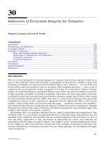
metal frame.
The questions below refer to Figure 13.20.
FIGURE 13.20 For Chapter 13 Self-Test question 13.13 through 13.17.
M
480 V
Three
phase
60Hz
L1
L2
L3
13.13
L1A
L2A
L3A
M-1
M-2
13.14
H1
H3 H2
H4
X1
X2
Off On
13.17
1A
1
1
Motor
Stop
13.16
M Aux
3
4
2
2
OL
13.15
M