Humanoid Robots Human-like Machines Part 3 pot
Bạn đang xem bản rút gọn của tài liệu. Xem và tải ngay bản đầy đủ của tài liệu tại đây (799.86 KB, 40 trang )
Multipurpose Low-Cost Humanoid Platform and Modular Control Software Development
71
current consumption; on servo motors that is not a simple task and further on some insight
is given about the process.
Still on the proprioceptive sensors, inertial perception is believed to be an advantage on yet-
to-come developments such as dynamic locomotion patterns. Integrated Micro-Electro-
Mechanical (MEMS) accelerometers (ADXL202E, Analog Device) and a gyroscope (ENJ03JA,
Murata) were selected and even installed, although they are not yet used to influence the
system control. Finally, for the extraceptive perception, a vision system using a camera is to
be mounted, although it is not yet used for decisions.
2.3.1 Measuring joint position
Servos have internal position feedback which is physically accessible by reading the internal
potentiometer used by the device controller. However a connection must be wired to the
output of the encapsulating box. Besides the tree default wires for power and input PWM
pulse, a fourth wire is added to provide a voltage level between the power ground which is
related to the potentiometer current position. The procedure, applicable in both the Futaba
or HITEC brands (and possibly others), is sketched in Figure 5.
2 kȍ
Potentiomete
r
Wire to access
internal feedback
Motor
Figure 5. Wiring the servo to fetch the internal position feedback
Conditions seem now to exist to obtain joint angular position, except for the fact that voltage
at the potentiometer output is not stable! Indeed, it depends on which part of the response
to the PWM pulse the servo is at each moment. It was verified that the potentiometer output
is only reliable during the duration of the pulse itself; once the pulse finishes, the servo
internal controller enters the period of power application to the motor windings and
interference will occurs as illustrated in Figure 6. A fine tuned software program had to be
developed to perform potentiometer reading duly synchronized with PWM generation to
ensure correct angular position evaluation.
Input PWM pulse
Potentiomete
r
position (variable)
“current” pulse
Amplitude
fixed at a
maximum
20 ms
Figure 6. Value of the servomotor potentiometer along the PWM pulse sequence
Humanoid Robots, Human-like Machines
72
2.3.2 Measuring current
The procedure described in the preceding section yielded another interesting outcome
which was the possibility to assess the current consumption by the servo. The “current
pulse” depicted in Figure 6 appears as a “pulse” occurring immediately after PWM falling
edge and its width has been related to the power applied to the motor windings; the larger
the pulse the more power is applied, or, as applied voltage is constant, the more
instantaneous current is being absorbed by the motor, or finally, more torque is yielded by
the motor. Measuring the width of the “current pulse” was done also in synchronization
with PWM pulse generation by a sampling process at a much higher frequency than the
PWM pulse itself which is 50 Hz.
2.3.3 Measuring foot reaction forces
To pursue a versatile platform that is expected to interact with the environment and be
reactive to it, it is a must to measure contact reaction forces with the floor. This is needed to
comply with floor irregularities and sloped paths, but ultimately it will provide direct
feedback for balance, also in standard floor conditions. The idea is then to include the
reaction forces in the control loop. Since miniature good quality load cells present
prohibitive costs (hundreds of dollars), the team decided to develop low-cost strain
gauge-based force sensors (Figure 7).
Four strain gauges
located underneath
Four force
application points
Adjustable Screw
Strain gauge
Flexible beam
Foot base
Figure 7. Model of sensitive foot and detail view of a force sensor on the foot
Figure 8. Electrical conditioning and amplification for the force sensor
Each foot possesses four of these sensors which allow for locomotion manoeuvres and
control, either to keep the platform “upright” or even to perform dynamic balance when
moving. The supporting material was made entirely of Plexiglas for greater flexibility and
easier manufacture. A flexible beam of thinner Plexiglas holds the gauge which is connected
to a Wheatstone bridge and an instrumentation amplifier with electrical conditioning and
Multipurpose Low-Cost Humanoid Platform and Modular Control Software Development
73
fine tuning components as shown in Figure 8. To compensate for asymmetric variations
(temperature, shot noise, etc.) measuring bridge presents several points of symmetry,
including a static strain gauge just for electric balancing purposes. Higher resistances than
shown can be later used to low power consumption by the bridge.
3. Distributed control architecture
As mentioned before, the intended platform should have distributed computational
capabilities either for modular and updatable software or for decentralized control
capabilities in order to be more robust. Distributed architectures are not new but some
systems (namely some smaller robots from those appearing in Robocup competitions) still
attach to one central and global controller. The proposed approach wants to be scalable, and
for so many degrees of freedom, one central controller simply is not practical.
The solution has then been to conceive a three level hierarchy of controllers: the lowest level,
named Slave Units (SU), is responsible for actuator direct control and sensor reading and
immediate processing; SUs may be in number of several. The second level comprises the so-
called Master Unit (MU) whose role is to gather and maintain the status of the system as
well as establish the communication protocols between levels. Finally, the Main Control
Computer (MCC) will communicate with the MU and external interfaces, and will be
responsible for the high level directives to be issued to the platform as a whole.
The Main Control, implemented as an embedded PC, will have computational power
enough to acquire images and process vision. It will run a high level operating system and
interfaces the MU by RS232 serial line. It issues orders of any level but does not ensure any
type of real time control loop. Orders are dispatched to the Master Unit as well as querying
status and other system variables, however not for real time control since there isn’t even
enough channel bandwidth for it. A general lay-out of the architecture appears in Figure 9.
The Slave Units are indeed in charge of system motion or static activity. Each slave unit is
capable of controlling three servomotors as well as acquiring sensorial data form up to 16
sensors. All slave units are connected by a CAN bus which also includes the MU.
Main Computer
CAN bus
RS-232
Master Unit
Slave Unit 1
(Right Leg)
Servo
1
Servo
2
Servo
3
Slave Unit 2
(Left Leg)
Servo
1
Servo
2
Servo
3
Slave Unit 3
(Right Hip)
Servo
1
Servo
2
Servo
3
Slave Unit 4
(Left Hip)
Servo
1
Servo
2
Servo
3
Figure 9. Concept of the distributed control architecture and one partial lay-out
Humanoid Robots, Human-like Machines
74
The Slave Units only send data to the bus when asked to. Their main task is to maintain
some local control law for each of the 3 servos, and possibly with variable feedback
depending on local sensors and/or other directives that might have reached the unit. A PIC
microcontroller is the centre of the processing unit and its main components are depicted in
Figure 10. All SU have conceptually the same program with variations that can dynamically
be imposed depending on the SU address which is hard-coded by on-board dip-switches.
Figure 10. Functional layout of a slave controller
The Master Unit has a similar layout as slave units, but it holds a completely different
program. The MU has normally no need to read any kind of sensors but it can do it if
necessary. From the point of view of the hardware implementation, the basic board is
similar, but a piggy-back board may be added where special sensors or other functions may
be attached to a particular board (Figure 11).
Figure 11. Complete Slave Unit (left); base board and two cases of piggy-back boards (right)
Multipurpose Low-Cost Humanoid Platform and Modular Control Software Development
75
The current stage of development of the humanoid robot designed and built in the scope of
this project is shown in Figure 12. All the proposed ideas and particular control algorithms
have been tested and verified on this real robot to form a critical hypothesis-and-test loop.
Figure 12. Biped humanoid robot with 22 DOFs
4. Low level joint control
Besides the computational resources, a major concern in building low-cost humanoid
platforms is the implementation of the low level controllers, together with the constraints on
the actuator systems. The success relies on the development of joint control algorithms and
sensing devices to achieve proper performance when tracking a commanded trajectory. In
this section, we will concentrate on the design and implementation of the local joint
controllers. First, we review the limitations of RC servomotors with pulse-width control and
how this affects our decisions. Then, we describe the implementation of an external position
control loop closed around each slave unit. Adopting an outer loop, we establish a new
control structure that introduces suitable compensation actions, significantly improving the
system’s performance and responsiveness.
4.1 Advantages and limitations of RC servomotors
The selected servomotors have themselves a built-in motor, gearbox, position feedback and
controlling electronics, making them practical and robust devices. The control input is based
on a digital signal whose pulse width indicates the desired position to be reached by the
motor shaft. The internal position controller decodes this input pulse and tries to drive the
motor up to the reference target based on the actual position determined by the
potentiometer attached to each motor. However, the controller is not aware of the motor
Humanoid Robots, Human-like Machines
76
load and its velocity may vary rapidly and substantially. By design, servos drive to their
commanded position fairly rapidly depending on the load, usually faster (slower) if the
difference in position is larger (smaller). As the control task becomes more demanding,
involving time-varying desired position (i.e., tracking control), the performance of the
internal controller begins to deteriorate.
In order to validate the practical findings and gain insight into these problems, an entire
system was set up intended to evaluate the actuator’s performance. The experimental
arrangement comprises several calibrated loads that will be applied to the servo shaft
through a linkage 10 cm long (Figure 13). The servo is fixed in a mechanical lathe such that
its zero position corresponds to the perpendicular between the link and the gravity vector.
Figure 13. Experimental setup to assess servomotor response to variable loads
The setup used for experimental testing includes a master and a slave unit controlling a
servomotor properly fixed and loaded. On the one side, the master unit is connected to a
computer through a RS-232 link, using MatLab software as the user’s interface. On the other
side, the slave unit is connected to the servo mechanism in two ways: (i) by sending the
desired servo position command as a pulse train with a given width; and (ii) by reading the
potentiometer feedback signal (the only feedback available). In the experiments conducted
below, the servo’s internal controller is the only responsible for the resulting performance.
In the following, results of two experiments are described: the first experiment is performed
with “large” steps (equivalent to 90º) for several loads and, then, a second experiment is
carried out with smaller steps (few degrees each) in order to simulate some kind of ramp
input and launching the basis for velocity control.
The results of applying a step input from -45º to +45º are presented in Figure 14 in terms of
the desired and the actual response for two loads (258g and 1129g). The first notorious
observation is the unstable dynamic behaviour on position reading, which shows at the
beginning a sudden jump to a position below -45º and some oscillations during the path up
to the final set point. Instead, the motor shaft presented a continuous and fast motion to the
final position without speed inversions or any kind of oscillations. This seems to indicate
that this process also requires care since the internal controller may interfere with the
voltage drop on the potentiometer that can affect external readings of the shaft position.
Another problem arising from the servo response, which may be critical as the load
HS805BB servo
link 10 cm long
load of 0.67 kg
Multipurpose Low-Cost Humanoid Platform and Modular Control Software Development
77
increases, is the considerable steady-state errors. Notice the presence of an appreciable value
of steady-sate error for the larger load (about 8º error remains after the transient phase).
Figure 14. Response to a step input (– 45º to +45º) in the reference
In order to carry out a fair comparison with the previous case the joint has been placed in
the same initial position (-45º) and should move to the same final position (+45º). However,
to implement some sort of velocity control, the experiment was carried out in a manner that
small position steps are successively requested to the servo controller. Their magnitude and
rate will dictate some sort of desired “average velocity”. This approach will generate an
approximately linear increase for the position, which is to say, some constant velocity.
The results are presented in Figure 15 in terms of the desired and the actual response to a
slope input. As above, and although the transient response has a very improved behaviour,
the steady state error still exists. An experiment was carried out to stress this effect: the
servo is requested to successively move a given load to some positions; for each position,
after motion completion, the potentiometer is sampled to obtain the real position that the
servo achieved. Relating the positional error with the static torque exerted in the joint, a
direct conclusion can be drawn: the higher the torque, the higher is the steady state error.
Figure 15. Response to a slope input in the reference
Humanoid Robots, Human-like Machines
78
In conclusion, dynamic effects and improper servo’s control turns the device into a highly
non-linear actuator with limited performance, which restricts the scope of their application.
Two common approaches can be devised to achieve higher performance: hardware
modification or software compensation. The price to pay following the first direction is,
often, the replacement of the electronics unit of the motor package by dedicated control
boards. On the other hand, it is expected that enhanced performance can also be achieved by
software compensation, provided that position and/or torque measurements are available.
4.2 Outer feedback control loop
The servo circuit has a narrow input control range and it is difficult to control accurately,
though it has adequate speed and torque characteristics. In most practical situations, an
effective strategy to improve the servo’s operation is using an external controller where an
outer position control loop is closed around the inner loop available in the servomotor.
Figure 16 illustrates the block diagram of the servo controller proposed to achieve enhanced
performance in terms of steady-state behaviour and trajectory tracking capabilities. The
algorithm is based on dynamic PWM tracking using the servo own potentiometer for
position feedback. For that purpose, the slave units have to track the motor positions (up to
3 motors) with time and adjust the PWM in order to accelerate or decelerate the joint
motions. Practical issues like computation time or lack of speed measurements are
challenged by devising the distributed architecture approach.
Reference
J
oint An
g
le Servo's Internal
Controller
Slave Local Unit
PWM Signal
PID Control
(outer loop)
HITEC Servomotor
Potentiometer
Signal
Computed
Joint Angle
Figure 16. Block diagram of the joint control: the inner loop consists of the servo’s own
controller; the outer control loop generates a dynamic PWM using feedback from the servo’s
potentiometer
The potential offered by the external control strategy to ensure an improved behaviour is
now investigated experimentally. For that purpose, several control schemes could be
implemented in the PIC microcontroller. The focus of the present study is on digital PID-
controller or any of its particular cases. The proposed control schemes are implemented in
discrete time at 20 ms sampling interval and, then, tested in a number of experiments using
the same setup as described before.
Two main considerations were made to guide the selection of the control structure. First, the
system to control is formed by a single joint axis driven by an actuator with pulse-width
Multipurpose Low-Cost Humanoid Platform and Modular Control Software Development
79
control. Second, it is worth noting that an effective rejection of the steady-state errors is
ensured by the presence of an integral action so as to cancel the effect of the gravitational
component on the output. These facts suggest that the control problem can be solved by an
incremental algorithm in which the output of the controller represents the increments of the
control signal. In this line of thought, it is irrelevant the main drawback with this algorithm
that cannot be used directly for a controller without integral action (P or PD). One
advantage with the incremental algorithm is that most of the computation is done using
increments only and short word-length calculations can often be used.
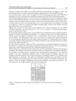
The first experiment is aimed at verify the effectiveness of the integral plus proportional
actions. In this case, it is chosen a demanding specification for the desired slope: each new
step position is update at the maximum rate of 50 Hz (corresponds to the PWM period) with
amplitude of 5 degrees. Let the desired initial and final angular positions of the joint to be
-ҟ90 and 50 degrees, respectively, with time duration of 1.12 seconds. The results are
presented in Figure 17 in terms of the time history of the desired and actual angular
positions, together with the trajectory errors for the full motion. It demonstrates the effect of
increasing K
I
for a fixed proportional term (K
P
= 0.04): it reduces the lag time improving
tracking accuracy, but at the expense of overshoot. Changing K
P
to a higher value (K
P
= 0.30)
minimises the overshoot, maintaining the lag time as for K
I
= 0.10. From these observations,
the role of each component can be deduced: (i) integral action reduces time lag at the
expense of an increased overshoot; and (ii) proportional action reduces overshoot,
deteriorating the establishment time for very high gains.
Figure 17. Behaviour of closed loop system with PI controller: the left graph shows the
response to a slope input in the reference with different values of the control parameters; the
right graph shows the trajectory errors for the full motion
Improvement of the position tracking accuracy might be achieved by increasing the position
gain constant K
I
, while controlling the overshoot effects by adjusting K
P
. However, for high
demands in terms of lag time, compensation tuning becomes very hard due to the presence
of unstable oscillations during transient response. A solution to this drawback can be
devised by rewrite the control algorithm aimed to include the proportional, integral and
derivative terms. At the same time, the second experiment includes a planning algorithm
used to generate smooth trajectories that not violate the saturation limits and do not excite
resonant modes of the system. In general, it is required that the time sequence of joint
variables satisfy some constraints, such as continuity of joint positions and velocities. A
Humanoid Robots, Human-like Machines
80
common method is to generate a time sequence of values attained by a polynomial function
interpolating the desired trajectory. A third-order polynomial function in joint space was
used to generate the reference trajectories. As result, the velocity has a parabolic profile and
the acceleration has a linear profile with initial and final discontinuities. Figure 18 illustrates
the time evolution obtained with the following initial and final conditions: q
i
= -45º, q
f
= 45º,
t
f
= 1.12 s. The gains of the various control actions have been optimized by trial and error in
such a way to limit tracking errors. As observed, significant improvements are achieved in
the servo’s response: zero steady-state error with no overshoot and limited tracking errors.
Figure 18. Behaviour of closed loop system with PID controller: the graph shows the
response to a third-order polynomial joint trajectory in the reference
4.3 Dual leg behaviour
In this subsection, the previous control approach applied to the single-axis system is
extended for the other robot’s joints. Although this development phase may be facilitated by
the reduction of performance demands and smaller joint excursions, the interpretation of the
last results deserves attention given the influence of the driving system. The humanoid
system is actuated by servomotors with reduction gears of low ratios for typically reduced
joint velocities. The price to pay is the occurrence of joint friction, elasticity and backlash
that contribute to the divergence between the commanded and the actual joint’s position. At
the lower level in the control system hierarchy lay the local controllers connected by a CAN
bus to a master controller. These slave control units generate PWM waves to control three
motors grouped by vicinity criteria (entire foot up to knee and hip joints) and monitor the
joint angular positions by reading the servo own potentiometer. There are two servo loops
for each joint control: the inner loop consists of the servo’s internal controller as sold by the
vendor; and the outer loop which provides position error information and is updated by the
microprocessor every 20 ms.
We now compare the robotic system’s behaviour when only the inner loop is present
(hereinafter “open-loop control”) and when the extra feedback loop is added (hereinafter
“closed-loop control”). In the later case, the outer servo loop gains are constant and tuned to
perform a well-damped behaviour at a predefined velocity. Once again, the joint trajectories
Multipurpose Low-Cost Humanoid Platform and Modular Control Software Development
81
along the path are generated according to a third-order interpolating polynomial with null
initial and final velocities. The next trial demonstrates the behaviour of the legs in the
double-support phase, while performing basic desired movements. More concretely, the
desired movements to be performed consist of: (i) a vertical motion from an upright
posture; and (ii) a lateral motion in which the leg leans sideways (±27 degrees). In both
cases, an additional load of 2.1 kg is attached to the upper part of the leg to emulate the
mass of other segments (Figure 19).
Figure 19. Snapshots of some stages in a motion sequence using two-legs and a load of 2.1
kg attached to the hip section: the top sequence shows the vertical motion; the bottom
sequence shows the lateral motion
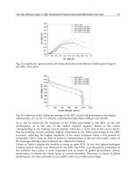
The experimental results in Figure 20 show the significant differences occurring in
performance of the two control schemes (open-loop and the cascading close-loop controller).
As expected, the open-loop control exhibits a poor performance, particularly for steady-state
conditions. Due to the imposed vertical motion, the limitations of the open-loop scheme are
more evident when observing the temporal evolution of the ankle (foot) joint. On the other
hand, an improved performance is successfully achieved with the proposed outer control
loop, both in terms of steady-state behaviour and enhanced trajectory tracking. Although
Humanoid Robots, Human-like Machines
82
further improvements could be possible by optimizing control gains, these results are
adequate in demonstrating the efficacy of the external loop compensation approach. Finally,
the performance of the servomotors is in accordance with theoretical considerations on the
choice of a motor-gear combination.
0 2 4 6 8
-60
-50
-40
-30
-20
-10
0
10
time (s)
Hip position (degrees)
Open Loop
Ki=0.10, Kp=0.80
Expected trajectory
0 2 4 6 8
-80
-60
-40
-20
0
20
40
time (s)
Knee position (degrees)
Ki=0.10, Kp=0.80
Open Loop
Expected trajectory
0 2 4 6 8
0
10
20
30
40
50
60
70
time (s)
Foot position (degrees)
Open Loop
Expected trajectory
Ki=0.10, Kp=0.80
0 1 2 3 4 5
0
5
10
15
20
25
30
35
time (s)
Foot position (degrees)
Open Loop
Expected trajectory
Ki=0.15, Kp=0.20
Figure 20. Comparison of performance between open and closed-loop control schemes: the
top and left-bottom charts show the behaviour of the three joints during the vertical motion;
the bottom-right chart shows the behaviour of the foot joint during the lateral motion
5. Force-driven local control
Balance maintenance is a core task for walking robots in order to engage useful tasks,
ranging from standing upright posture to motion goals. The difficulty lies in the uncertainty
of the environment and the limitations of the contact between the robot and the
environment. Over the last years it becomes evident the dichotomy in the fundamental
approaches of motion planning and control. On the one side, trajectory replaying
approaches rely on accurate models of the walker being characterised by pre-planned
trajectories that are played back during walking and, often, modified online through
feedback (Sugihara et al., 2002; Yamasaki et al., 2002; Kajita et al., 2003). On the other side,
realtime generation approaches ensure that planning and control are executed in a unified
way. Gait trajectories are computed online feeding back the actual state of the system in
accordance with the specified goal of the motion (Hirai et al., 1998; Denk & Schmidt, 2001;
Multipurpose Low-Cost Humanoid Platform and Modular Control Software Development
83
Bourgeot et al., 2002). The combination of both approaches can be useful when adapting to
deterministic but a priori unknown ground surfaces.
This section shows an example that is being developed to demonstrate the possibility of
achieving proper humanoid leg balancing using a local control approach. To this purpose, it
is considered feedback control from several sensors, including angular position in each joint
and four force sensors inserted into the foot corners. The sensors provide information about
the ground reaction forces and the location of the centre of pressure (COP). This opens up
new avenues and possibilities for distributed architectures where centralised and local
control co-exist and concur to provide robust full monitoring and efficient operation.
5.1 Adaptive leg balancing
The ability to balance in single support, while standing on one leg, is an important
requirement for walking and other locomotion tasks. In the previous section, the approach
to balance control assumed the presence of explicitly specified joint reference trajectories
and calculations based on static configurations to derive the necessary PWM input signal.
The goal of this section is to present the developed control algorithm that provides
enhanced robustness in the control of balancing by accounting for the ground reaction
forces. Thus, the system is able to stand on an uneven surface or one whose slope suddenly
changes (Figure 21). In a similar way, the control system could sense that it has been
pushed, using the force sensors in the soles of its foot, and acts to maintain the postural
stability. The open challenge is to allow local controllers to perform control based on sensor
feedback and possibly a general directive. Here, the global order is to keep balance in a
desired COP location and, although all actuators can intervene, the ankle joints have the
relevant role to keep an adequate force balance on each foot.
Figure 21. Single leg balancing on top of a surface with variable slope
The controller presents the following key features. First, the force sensors are used to
measure the actual COP coordinates, instead of calculating other related variables, such as
the centre of mass location. Second, the control system commands the joint actuators by
relating the joint velocities (
q
) to the error (e) between the desired and the current position
of the COP. The choice of the relationship between
q
and e allows finding algorithms with
Humanoid Robots, Human-like Machines
84
different performances. The simplest method is the straightforward application of a
proportional law, so that:
=
qKe (2)
The controller is independent of the robot’s model or any nominal joint trajectory. This
approach has the main advantage of its simplicity: each component of the error vector
relates directly and in an independent way to the ankle joints (pitch and roll joints), due to
their orthogonal relations. Alternatively, by interpreting a small displacement in the joint
vector as a torque and the error vector as a force suggests the following update law:
T
=
qJKe (3)
Here,
T
J is the transpose of the COG Jacobian matrix which transforms the differential
variation in the joint space into the differential variation of the COG’s position and K is a
diagonal matrix properly chosen to ensure convergence. Another requirement is now
imposed in order to stabilize the hip height: the error vector accounts for the operational
space error between the desired and the actual end-effector position. Then, the Jacobian
translates desired Cartesian motions of selected parts of the leg into corresponding joint
space motions.
5.2 Experimental results
The following analysis illustrates the emergence of an appropriate behaviour when the
system stands on a moving platform. The desired goal is to stand in an initial posture, while
the control system relies on the reaction force data to estimate slope changes in the support
surface. As stated before, the emphasis in this work is on procedures that allow the robot to
calibrate itself with minimal human involvement. Thus, after an initial procedure in which
the humanoid leg is displaced to the desired posture, the control system generates online the
necessary joint adjustments in accordance with the pre-provided goal. The joint velocity
values are computed in real time to modify dynamically the corresponding PWM signal. A
joint velocity saturation function is used to avoid abrupt motions, while satisfying dynamic
balance constraints.
The experimental results highlight the time evolution of the COP and the resulting ankle
joint angles accordingly to the control laws presented above, while the humanoid leg adapts
to unpredictable slope changes. Figure 22 and Figure 23 show the achieved behaviour for a
predominant leg’s motion in the sagittal plane, using both the proportional and the
Jacobian-based control laws. Figure 24 and Figure 25 report the leg’s behaviour for a
predominant motion in the lateral plane. In both cases, the use of the proposed control
algorithm gives rise to a tracking error which is bounded and tends to zero at steady state.
This indicates that the posture was adjusted and the differences on the ground reaction
forces become small. The algorithm based on the COG Jacobian provides a computationally
efficient solution for simple models. For a practical humanoid, the Jacobian may be a
complex non-linear matrix requiring fast and accurate calculations using a numerical
approach. Ongoing work is exploiting the case when the reference COP is a time-varying
function.
Multipurpose Low-Cost Humanoid Platform and Modular Control Software Development
85
Figure 22. Leg’s behaviour with predominant motion in the sagittal plane using the
proportional law: temporal evolution of the centre of pressure (up) and joint angular
positions (down)
Figure 23. Leg’s behaviour with predominant motion in the sagittal plane using the
Jacobian-based method: temporal evolution of the centre of pressure (up) and joint angular
positions (down)
Humanoid Robots, Human-like Machines
86
Figure 24. Leg’s behaviour with predominant motion in the lateral plane using the
proportional law: temporal evolution of the centre of pressure (up) and joint angular
positions (down)
Figure 25. Leg’s behaviour with predominant motion in the lateral plane using the Jacobian-
based method: temporal evolution of the centre of pressure (up) and joint angular positions
(down)
Multipurpose Low-Cost Humanoid Platform and Modular Control Software Development
87
6. Conclusion
In this chapter we have described the development and integration of hardware and
software components to build a small-size humanoid robot based on off-the-shelf
technologies. A modular design is conceived to ensure easy maintenance and faster
reproducibility. The most relevant feature of this implementation includes the distributed
architecture in which independent and self-contained control units may allow either a
cooperative or a standalone operation. The integration in these simpler control units of
sensing, processing and acting capabilities play a key role towards localised control based
on feedback from several sensors.
The adoption of an outer motion control loop to provide accurate trajectory tracking was
presented and has been experimentally demonstrated. The strength of this approach lies in
its performance, generality and overall simplicity. The humanoid platform reached a point
where intermediate and high level control can now flourish. An example has been given for
a kind of intermediate level control implemented as a local controller. From there, a force-
driven actuation was successfully applied to demonstrate the possibility of keeping the
humanoid robot in upright balance position using the ground reaction forces.
Ongoing developments on the humanoid platform cover the remainder hardware
components, namely the inclusion of vision and its processing, possibly with a system based
on PC104 or similar. A full autonomous humanoid robot for research is being developed
that allows testing and evaluation of new ideas and concepts in both hardware and software
modules. Future research, which has already started, will cover distributed control,
alternative control laws and also deal with issues related to navigation of humanoids and,
hopefully, cooperation. Force control techniques and more advanced algorithms such as
adaptive and learning strategies will certainly be a key issue for the developments in
periods to come in the near future.
7. Acknowledgments
The authors would like to thank the following students at the University of Aveiro for their
support in the humanoid hardware and software development: David Gameiro, Filipe
Carvalho, Luis Rego, Renato Barbosa, Mauro Silva, Luis Gomes, Ângelo Cardoso, Nuno
Pereira and Milton Ruas.
8. References
Bourgeot, J M., Cislo, N. & Espiau, B. (2002). Path-planning and Tracking in a 3D Complex
Environment for an Anthropomorphic Biped Robot, Proceedings of the IEEE
International Conference on Intelligent Robots and Systems, pp. 2509-2514, October
2002, Lausanne, Switzerland.
Denk, J. & Schmidt, G. (2001). Synthesis of a Walking Primitive Database for a Humanoid
Robot Using Optimal Control Techniques, Proceedings of the IEEE International
Conference on Humanoid Robots, pp. 319-326, November, 2001, Waseda, Japan.
Furuta, T. et al. (2001). Design and Construction of a Series of Compact Humanoid Robots
and Development of Biped Walk Control Strategies, Robotics and Automation
Systems, Vol. 37, pp. 81-100.
Humanoid Robots, Human-like Machines
88
Hirai, K. et al. (1998). The Development of Honda Humanoid Robot, Proceedings of the IEEE
International Conference on Robotics and Automation, pp. 1321-1326, May 1998,
Leuven, Belgium.
Huang, Q., Nakamura, Y. (2005). Sensory Reflex Control for Humanoid Walking, IEEE
Transactions on Robotics, Vol. 21, nº. 5, pp. 977-984.
Lohmeier, S. et al. (2004). Computer System and Control of Biped “Johnnie”, Proceedings of
the IEEE International Conference on Robotics and Automation, pp. 4222-4227, April–
May 2004, New Orleans, USA.
Kajita, S. et al. (2003). Resolved Momentum Control: Humanoid Motion Planning Based on
the Linear Angular Momentum, Proceedings of the IEEE International Conference on
Intelligent Robots and Systems, pp. 1644-1650, October 2003, Las Vegas, USA.
Kaneko, K et al. (2004). Humanoid Robot HRP-2, Proceedings of the IEEE International
Conference on Robotics and Automation, pp. 1083-1090, April–May 2004, New Orleans,
USA.
Kim, J H. et al. (2004). Humanoid Robot HanSaRam: Recent Progress and Developments,
Journal of Comp. Intelligence, Vol 8, nº. 1, pp. 45-55.
Nagasaka, K. et al. (2004). Integrated Motion Control for Walking, Jumping and Running on
a Small Bipedal Entertainment Robot, Proceedings of the IEEE International Conference
on Robotics and Automation, pp. 3189-3194, April–May 2004, New Orleans, USA.
Popovic, M., Goswami, A. & Herr, H. (2005). Ground Reference Points in Legged
Locomotion: Definitions, Biological Trajectories and Control Implications, The
International Journal of Robotics Research, Vol. 24, nº. 12, pp. 1013-1032.
Ruas, M., Silva, F. & Santos, V. (2006). Techniques for Velocity and Torque Control of RC
Servomotors for a Humanoid Robot, Proceedings of the 9
th
International on Climbing
and Walking Robots, pp. 636-642, September 2006, Brussels, Belgium.
Sakagami, Y. et al. (2002). The Intelligent ASIMO: System Overview and Integration,
Proceedings of the IEEE International Conference on Intelligent Robots and Systems, pp.
2478-2483, October 2002, Lausanne, Switzerland.
Sugihara, T., Nakamura, Y. & Inoue, H. (2002). Realtime Humanoid Motion Generation
Through ZMP Manipulation Based on Inverted Pendulum Control, Proceedings of
the IEEE International Conference on Robotics and Automation, pp. 1404-1409, May
2002, Washington, USA.
Silva, F. & Santos, V. (2005). Towards an Autonomous Small-Size Humanoid Robot: Design
Issues and Control Strategies, Proceedings of the IEEE International Symposium on
Computational Intelligence in Robotics and Automation, June 2005, Espoo, Finland.
Yamasaki, F. et al. (2000). PINO the Humanoid: A Basic Architecture, Proceedings of the
International Workshop on RoboCup, August–September 2000, Melbourne, Australia.
Yamasaki, F. et al. (2002). A Control Method for Humanoid Biped Walking with Limited
Torque, In: RoboCup 2001, A. Birk, S. Coradeshi & S. Tadokoro, (Ed.), pp. 60-70,
Springer Verlag, Berlin Heidelberg.
5
Artificial Muscles for Humanoid Robots
Bertrand Tondu
LESIA, Institut National de Sciences Appliquées de Toulouse
Campus Universitaire de Rangueil, 31077 Toulouse
France
1. The question of actuator choice for humanoid robots
It is important to recall that humanoid robot technology derives from the technology of
industrial robots. It is obvious that the developments of bipedal robots such as the
integration of robot-upper limbs to complex anthropomorphic structures have benefited
from progress in mechanical structures, sensors and actuators used in industrial robot-arms.
A direct link is sometimes made between the technology of redundant robot-arms and
humanoid robots as underlined in some technical documents of the Japanese AIST where it
clearly appears that the HRP2 humanoid robot upper limb is directly derived from the
Mitsubshi PA10 7R industrial robot-arm.
Due to its high number of degrees of freedom in comparison to industrial robots, a
humanoid robot requires great compactness of all actuator and sensor components. This is
why we believe that the harmonic drive technology associated with direct current electric
motor technology has played a non-negligible part in humanoid robot development. The
DC actuator offers the great advantage of being a straightforward technology, associated
with simple and well-known physical models, its integration into mobile robots benefits
from new developments in embedded batteries. However, its low maximum-torque-on-
mass and maximum-torque-on- volume ratios are a serious drawback for its use in direct
drive apparatuses. On the other hand, the ability of electric motors to generate very high
velocities in comparison with moderate jointed velocities needed by industrial robot-arms
and more by jointed anthropomorphic limbs, gives the possibility of using high ratio speed
reducers to amplify motor-torque. Moreover, the choice of a high ratio speed reducer offers
the advantage of masking inertial perturbations such as external torque perturbations. The
technical achievement of such ratios induces specific mechanical difficulties due to the
bulkiness of successive gears; harmonic drive technology – represented for example by
Harmonic Drive AG – resolves this problem in a very elegant manner: the harmonic drive
and the actuator fit together without excessive increase in mass and volume in comparison
with the actuator alone. It can be considered that most of today’s humanoid robots are
actuated by DC motors with harmonic drives (this actuation mode is mentioned, for
example, by Honda from its first paper about the P2 robot onwards (Hirai et al., 1998) and
then in the official ASIMO web site, as well as in papers concerning other Japanese and
European humanoid robots). But if this technology simplifies actuator mechanical
integration and leads to the use of simple joint linear control, despite the highly non-linear
character of robot dynamics, it is well-known that the use of a speed reducer multiplies the
Humanoid Robots, Human-like Machines
90
joint stiffness by the its ratio squared. A high joint stiffness contributes to joint accuracy and
repeatability, but also induces a high danger level for users, which can be acceptable in the
case of industrial robot-arms separated from factory staff by special safety devices, but
becomes very problematical in the case of humanoid robots intended for working in public
environments. The need to find an actuation mode which associates power, accuracy and a
‘softness’ adapted to human presence, that is the question of actuator choice in humanoid
robotics. To address this problem we will first try to define the notion of artificial muscle in
paragraph 2, then deal with the question of artificial muscle actuators for humanoid robots
in paragraph 3, before analysing their integration within anthropomorphic limbs (paragraph
4) to finish with their control (paragraph 5).
2. Notion of artificial muscle
2.1 Performance criteria in the research of new actuators
A general theory of actuators does not exist; each actuator is defined according to the
physical theory on which its legitimacy is founded. A comparison of actuators can as a
consequence be delicate. This is why actuator designers have introduced a certain number
of performance criteria aimed at making such comparisons easier. In general, actuation can
be defined as a process of converting energy to mechanical forms, and an actuator as a
device that accomplishes this conversion. Power output per actuator mass, and per
volume, as actuator efficiency – defined as ‘the ratio of mechanical work output to energy
input during a complete cycle in cyclic operation ‘ (Huber et al., 1997) - are three
fundamental properties for characterizing actuators. However, artificial muscle technology
considers more specific performance criteria so as to accurately specify new actuator
technology in comparison with ‘natural muscular motor’ properties. The following
terminology, justified by the linear actuator character of the artificial muscle, generally
completes the power criteria – the definitions given in inverted commas are from (Madden
et al., 2004) :
• Stress : ‘typical force per cross-sectional area under which the actuator materials are
tested’; maximum stress corresponds to the maximum stress that can be generated in
specified functioning conditions; as will be seen later, it is important for a given
technology to specify the ‘actuator materials’ relating to stress: typical stresses of strips
or fibres of a given technology is not obligatorily similar to that of the artificial muscle
composed of a set of these strips or fibres;
• Strain : ‘displacement normalized by the original material length in the direction of
actuation’; maximum strain and maximum stress are according to Huber & others
‘basic characteristics of an actuator [since] for a given size of actuator they limit the
force and displacement’ (Huber et al., 1997, p. 2186); the terms contraction ratio and
maximum contraction ratio will also be used;
• Strain rate : ‘average change in strain per unit time during an actuator stroke’; the term
‘response time’ – in the sense given by control theory, will also be used to characterize
the speed of artificial muscle dynamic contraction;
• Cycle life : ‘number of useful strokes that the material is known to be able to undergo’;
this notion specifies the heavy-duty character of artificial muscle in given working
conditions; in practice this is an important notion since artificial muscles are essentially
made of ‘soft’ materials which can be weakened by shape changes imposed by the
actuation mode;
Artificial Muscles for Humanoid Robots
91
• Elastic modulus: ‘material stiffness multiplied by sample length and divided by cross-
sectional area’; this is a typical material science notion; when the artificial muscle is
considered as an actuator to be controlled, stiffness – and its inverse - compliance
notions can appear more appropriate.
It is important to note that this criteria list is not exhaustive; depending on author, other
performance criteria can be found: as an example, Huber et al consider two criteria not
listed above: actuator density (the ratio of mass to initial volume of an actuator) and strain
resolution (the smallest step increment of strain) (Huber et al., 1997). The first directly
concerns humanoid robotics: like skeletal muscles, artificial muscles are assumed to be
located in moving robot links; the second criterion can be interesting in a control
perspective to specify artificial muscle sensitivity.
Furthermore, we believe that the theoretical framework proposed by Hannaford and
Winters (Hannaford & Winters, 1990) for the analysis of actuator properties based on
Paynter’s terminology of generalized dynamic systems (Paynter, 1961) can be particularly
useful in our study: these authors propose characterizing any actuator by its two effort-flow
and effort-displacement characteristics, where ‘effort’ represents the output force or torque,
and ‘flow’ the linear velocity or angular velocity. For example, the DC motor is ideally
characterized by a linear effort-flow curve and a constant effort-displacement curve, as
illustrated in Figures 1.a and 1.b. Figures 1.c and 1.d give the typical characteristics of the
skeletal muscle by the association of ‘effort-flow’ characteristics corresponding to the so-
called tension-velocity curve with the ‘effort-displacement’ characteristics corresponding to
the so-called tension-length curve. We will return to this in the modelling of skeletal
muscle, but it is important to note the fundamental originality of skeletal muscle
characteristics: while most of the actuators have constant or pseudo-constant ‘effort-
displacement’ characteristics, this is not so for skeletal muscle. As a dynamic system in
Paynter’s sense, the ‘effort-displacement’ relationship defines passive element C (for
compliance or capacitance). Classical actuators generally have infinite compliance; a
dependence of force/torque on position can even appear as a drawback: it is up to the
actuator control and not the actuator itself to impose this dependence. Conversely, living
actuators aimed at a ‘relationship life’ have to combine the generation of the power
necessary for body mobility with a non-infinite compliance making for easy contact with the
environment – we will use later the term ‘natural’ compliance to characterize this
compliance peculiar to the skeletal actuator. Research on artificial muscles can be
understood as a new attempt to mimic the living so as to integrate it into a machine – the
humanoid robot – an original power-softness combination, yet glaringly absent in machine
technology.
2.2 The historical Kühn and Katchalsky notion of artificial muscle as a gel swelling
and deswelling under the effect of a chemical agent
The origin of the artificial muscle notion must be found in the first works of chemists on
certain materials whose swelling can be controlled in a reversible manner. At the end of the
1940s, Kühn & Katchalsky did indeed prove that an aqueous polymeric gel essentially
composed of polyacrylic acid ‘… is found to swell enormously on addition of alkali and to
contract rapidly when acid is added to the surrounding solution. Linear dilatations and
contractions of the order of 300 per cent were observed. This cycle of swelling and de-
swelling is reversible and can be repeated at will ‘ (Kühn et al., 1950, p.515). At that time the
Humanoid Robots, Human-like Machines
92
authors had designed a device transforming chemical energy into mechanical working in
the form of a 0.1 mm thick filament able to lift up a 360 mg load in some minutes when
swollen. Thus the original Kühn & Katchalsky experiment historically created the present
artificial muscle notion as a reversible contractile device. Katchalsky emphasized the
natural tendency of artificial muscles to generate an ‘equilibrium swelling’ brought
according to him about two opposing tendencies : first, ‘…the solution tendency of the
polymeric molecules and the osmotic pressure of the cations of the alkali bound by the gel’,
secondly ‘…the caoutchouc-type contraction tendency of the stretched polymer molecules’
(Katchalsky, 1949, p.V/8). More generally, we will go further and apply this natural
tendency to an equilibrium state of any artificial muscle type as an open-loop stability in
position. It is important to note, however, that this ability to pass from an equilibrium state
to another state would be nothing if it were not associated to a reversibility whose life cycle
is finally its measure. Note also that the life cycle of natural muscle is greater than 10
9
(Hunter & Lafontaine, 1992); no present-day artificial muscle is able to approach this value,
which is linked to the ability of living tissues to self-repair. Kühn & Katchalsky’s historical
studies were reconsidered in the 1980s within the framework of a renewed interest for
artificial muscles due to technological developments in robotics, and a demand for
implantable artificial biological organs. However, from a practical point of view, the Kühn
& Katchalsky actuator displays a major disadvantage: its excessively slow response time (in
the order of minutes). More generally, it will be seen throughout this chapter that the major
difficulty in the design of artificial muscles for robots consists of obtaining both quick
response time and high-power-stress to mass-and-power to volume, adapted to the
integration of artificial muscles to human-dimensions and mass anthropomorphic limbs.
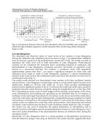
There now follows a brief overview of present-day artificial muscle technologies.
(a)
(b)
(c)
(d)
Figure 1. Characterization of artificial and natural actuators based on ‘effort-flow’ and on
‘effort-displacement’ relations (inspired from (Hannaford & Winters, 1990), (a) and (b) Case
of the DC motor, (c) and (d) Case of the skeletal muscle (from (Winter, 1969))
Displacement
Torque
Velocity
T
o
r
q
u
e
Artificial Muscles for Humanoid Robots
93
2.3 The artificial muscle as any material structure exhibiting a reversible shape
change by a chemical or a physical agent
a. Contractile polymer gels
Aqueous solutions of polymeric acids considered by Kühn & Katchalsky are a particular
case of solvent-swollen crosslinked polymer gels that respond to changes in temperature,
pH, solvent, illumination, or other physical or chemical stimuli. The choice of pH or a
solvent as a stimulus applied to typically polyacrylamide (PAM), polyvinyl alcohol-
polyacrylic acid (PVA-PAA) or polyacrylonitrile (PAN) fibers or strips (all commercially
available) is particularly interesting due to the facility of producing the pH variation by
adding of acid or alkali solutions (typically through the control of the hydrogen ion by
means of chemical reactions with HCl and NaOH) or the facility of using cheap and readily
available solvent like acetone. Parallel to a better understanding of gels physics it has been
possible to develop micro sized gel fibers contracting in seconds and even tenths of seconds
and to increase both the force produced by gel fibers as resistance fibers (some of them can
support loads of about 100 N/cm
2
approximatively equal to that of human muscle. M.
Suzuki, for example, has developed in the nineties a 12 cm length artificial muscle model by
PVA-PAA-PA1Am gel film of 50μm thickness able to raise a ball of 2 g from a lower
equilibrium position to an upper equilibrium position within 10 s (Suzuki, 1991). Although
in these conditions, the maximum power density obtained with gel fibres can indeed be
estimated as being close to that of skeletal muscle, it still appears difficult to apply this
technology to the actuation of human-sized robot limbs. However, later we will analyse the
interesting attempt made at the MIT in the 1990s to promote ‘pH muscle’
The relative slowness of the complete contraction-elongation cycle of ion sensitive gel fibre
is mainly due to the relative slowness of the ion sensitive mechanism itself. For this reason,
other stimulus modes were considered, in particular heat transfer since heat diffusion is
better than ion diffusion. Thermo-responsive polymer hydrogels are already used in drug
release, and the study of tensile properties of thermo-responsive gels have been clearly
established (Kim et al., 2005). In the field of artificial muscles, this stimulus mode seems,
however, to have been more studied in the case of fairly recent polymer types – in particular
liquid crystal polymers – assumed to respond quicker than gel fibres. In any case, for gels as
for other materials, thermal response always appears quicker in the heating than in the
cooling phase (we will not deal in this chapter with the promising technology of liquid
crystal polymers able to respond to a luminous flash in less than a second, but as noted by
De Gennes (De Gennes et al., 1997) which predicted their contractile possibilities and talked
of them as ‘semi-quick artificial muscles’, the return to low temperatures is slow).
b. Shape memory alloys
Another form of reversible thermal response can be generated by means of thermally
activated shape memory alloys based on the ‘shape memory effect’ discovered at the
beginning of the 1950s. Among available materials nickel-titanium alloys (NiTi or nitinol)
are particularly interesting for actuation use because of their low cost and electrical
resistivity which heats the material by passing an electrical current. Due to this Joule
heating, NiTi contraction and expansion cycles can occur based on transformations from
martensitic to austenitic phases. Typically a shape is ‘memorized’ at a high temperature
(600°) placing the nitinol in austenite phase. On decreasing the temperature, the material
reverts to the martensite phase. When an external stress is applied, and as the material is
reheated at a lower temperature the material, because of the instability of the martensite
Humanoid Robots, Human-like Machines
94
phase at these temperatures, returns to its well-defined high-temperature shape. In the
shape memory effect, the material exhibits residual strains that can be used to generate a
linear displacement. The possibility of developing NiTi fibres exhibiting both very high
strain rates (300%/s) and very high stress (200 MPa) (Hunter & Lafontaine, 1992) naturally
interested the designers of new robot actuators. Safak and Adam (Safak & Adams, 2002), for
example, developed a lobster robot actuated by antagonistic nitinol artificial muscle pairs.
Figure 2 shows an interesting application of nitinol to miniature humanoid robotics: the five
fingers of the miniature robot hand can react at 0.2 s constant times to grasp light objects
(Maeno & Hino, 2006). Besides the current need for small sizes to obtain quick responses,
the main drawback of nitinol-type artificial muscles is its limited maximum strain: about
5%, which is very far from the natural skeletal muscle’s 40 %. Moreover, the life cycle
becomes more limited as the strain increases.
Figure 2. Miniature robot-hand actuated by Nitinol shape memory alloy artificial muscles
controlled by heat transfer (from (Maeno & Hino, 2006))
The shape memory effect can be controlled not only by heat transfer, but also by means of
an electric field which offers the advantage of being an easier control parameter.
Ferromagnetic shape memory actuators have been largely studied and commercial versions
exist able to develop maximum strains of 10%, typical strain rates of 10 000%/s and typical
stresses of 1 Mpa to 9 MPa (Madden et al., 2004). However, the requirement of high
intensity magnets is a major drawback for human-sized robot-limbs. Finally, as for
thermally activated shape memory alloys, the difficulty of accurately controlling muscle
contraction is not a good point for applications to robotics. The same difficulty occurs with
recent conducting shape memory composites.
c. Electroactive polymers : From ionic polymer gels to ionic polymer-metal composites
It was demonstrated in the 1960s that the swelling/shrinking of ionic polymeric gels
generated by pH variation can also be obtained electrically. When an electric field is applied
to a strip of PAM, PAMPS or PAA-PVA, for example suspended in a surfactant solution, the
gel shows significant and quick bending towards the anode. According to Segalman and
others (Segalman et al., 1992) this is caused by the migration of unbound counter ions in the
gel, and the impingement of solvent ions at its surface which produce the strip bending.
The reversible phenomenon has been applied to the design of chemomechanical mobile
systems such as Shahinpoor’s swimming robot (Shahinpoor, 1992) or to polymer gel fingers
(Hirose et al., 1992). However, the application to linear actuators appears disappointing, as
recently reported by Choe and Kin who studied polyacrylonitrile linear actuators (Choe &
Kim, 2006): the tested fibre is a 10 mm long ‘single strand’ consisting of multiple filaments
Artificial Muscles for Humanoid Robots
95
(about 2000) whose diameter in the contracted state is about 0.5 mm, and 1.2 mm in the
elongated state; experimentally the fibre can produce a 0.1 N maximum force in both pH
activation and electric activation cases, but while this static tension is generated in fewer
than 10 s with a 1M HCl acid solution, it takes approximately 10 min for the same result
with a 5V electric field
If the electrostatic approach of ionic polymer-gel based linear actuators is unsatisfactory, it
can be asked if more interesting results could be obtained using conductive polymers.
Efforts to develop conductive polymer artificial muscles can be viewed as the search for
associating polymer mechanical properties with the ease of electric field control. In general,
conductive polymers are electronically conducting organic materials featuring conjugated
structures, able to undergo dimensional changes in response to changes in the oxidation
state. Polyaniline, trans-polyacetylene and polypyrrole are three examples of such
employed structures. When, for example, a conducting polypyrole film is electrochemically
oxidized, positive charges are generated along the chains and hydrated counter ions from
the solution are forced to penetrate into the polymer in order to compensate for these
positive charges. This induces an opening of the polymer structure and an increase in its
volume. A reduction in polymer induces the reverse effect: positive charges are eliminated
due the injected electrons: the polymer recovers its neutral state and the film volume
decreases. This swelling-shrinking property can be applied to the design of artificial
muscles such as the bilayer structure, consisting of a conducting and flexible polypyrolle
layer adhering to an elastic and non-conducting film, proposed by Otero and Sansinena
(Otero & Sansinena, 1995), or the monolayer structure by assembling two different
polypyrroles (Ochoteco et al., 2006). The resulting actuator is a bending type reacting in an
aqeous solution under low intensity current variation. According to Madden & others a
maximum 12% strain and a maximum 12%/s strain rate can be expected (Madden et al,
2004), consequently quicker than electrically-activated ionic polymer gels; however,
conductive polymers suffer from the same major drawback as ionic polymer actuators: they
need to be contained in a solvant bath.
The class of Ionic Polymer-Metal Composites (IPMC) can thus appear as a successful
attempt to maintain the ionic polymer contractile principle without the need for a solvant
bath. An IPMC is an ionic polymer in a composite form with a conductive metallic medium
such as platinium. The nafion developed by DuPont de Nemours & Co. is generally used as
a cation exchange thin membrane with metal electrode plated on both faces. Recently,
liquid nafion has been used to manufacture IPMC strips in various thicknesses (Kim &
Shahinpoor, 2002). Although they operate best in a humid environment, they can be
designed as self-contained encapsulated actuators to operate in various environments. As
theorized by Shahinpoor (Shahinpoor, 2002) an electric field induces a change in ion
concentration which attracts water molecules to one side of the polymer. Non-uniform
distribution of water produces a swelling on one side of the actuator, while the other side
contracts. The bending movement of the strips toward the anode is obtained at a low
voltage (typically 2V), and increases for higher voltages (typically up to 10 V) with a
reaction speed between μs and s. Because the IPMC does not produce linear actuation,
except in the case of fish-type mobile robots, its application to robotics is limited to gripping
mechanisms able to lift a few grams (Shahinpoor et al., 1998). The low stress generated by
IPMC - 10 to 30 MPa (Shahinpoor et al. 1998) - is another drawback of this type of artificial
muscle.