Humanoid Robots - New Developments Part 10 docx
Bạn đang xem bản rút gọn của tài liệu. Xem và tải ngay bản đầy đủ của tài liệu tại đây (800.99 KB, 35 trang )
Copycat Hand - Robot Hand Generating Imitative Behaviour at High Speed and with High Accuracy 307
shapes of the hand. Fig.1 shows a schematic chart of the interpolation of the articular angle
data and the CG images of the hand. Furthermore, Fig.2 shows an example of the
interpolated CG images of the hand. This figure represents an example of a case where the
articular angle was measured at three different points in time for the actions of changing
from ‘rock’ to ‘scissors’ in the rock-paper-scissors game, and the direct generation of CG and
the generation of CG using interpolation were made from two adjoining data. In both these
figures, the three images surrounded by a square represent the former, while the other
images represent the latter.
Fig. 1. Interpolation of the articular angle data and CG images of the hand.
Fig. 2. Examples of the interpolated CG images of the hand.
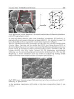
Third, we added the data describing the differences among individuals. Because of the
differences that exist among individuals (as shown in Fig.3), a wide variety of data is
required for a database intended for searching similar images. For example, in the hand
shape representing ‘rock’ in the rock-paper-scissors game, a significant difference
among individuals is likely to appear in (1) the curvature of the coxa position of the
four fingers other than the thumb and (2) the manner of protrusion of the thumb coxa.
Key angle information Key CG hand
Interpolation of
articular angle
Inter
p
olation of CG ima
g
es
308 Humanoid Robots, New Developments
Moreover, differences are likely to appear in (3) the manner of opening of the index and
the middle finger and (4) the standing angle of the reference finger in the ‘scissors’
shape, and also in (5) the manner of opening and (6) the manner of warping, etc. of the
thumb in the ‘paper’ shape. In order to express such differences among individuals in
the form of the CG hand, we need to adjust the parameters of the length of the finger
bone and the movable articular angle; therefore, we generated the CG images of hands
having differences among individuals on the basis of the articular angle data obtained
by the procedure described above. Fig.4 indicates an example of the additional
generation of the CG hand in different shapes. In the figure, the X axis shows CG hands
arranged in the order starting from those with larger projections of the thumb coxa,
while the Y axis represents those with larger curvature formed by the coxa of the four
fingers other than the thumb, respectively.
Fig. 3. Examples of the differences among individuals.
By performing the first to third steps mentioned above, we generated a total of 15,000 CG
hand images using this system.
Then, the resolution was changed. Although the CG image generated this time had a
resolution of 320 x 240 pixels, a substantial calculation time is required in order to estimate
the posture and for applying various image processing techniques. In the present study, a
reduced resolution of 64 x 64 was used. The pixel value after the resolution was changed is
given by the following expression:
¦¦
kl
ljkigo
r
jigr )64/320*,64/320*(
1
),(
(1)
Manner of opening
Manner of warping
Curvature of the coxa position of four fingers other than the thumb
Manner of protrusion of the thumb coxa
Manner of opening
Difference in reference angle
(a)
(b)
(c)
Copycat Hand - Robot Hand Generating Imitative Behaviour at High Speed and with High Accuracy 309
Fig. 4. Examples of the supplemented data of the differences among individuals.
Here, gr(i,j) and go(i,j) are the pixel values at row i and column j after and before altering the
resolution, respectively. Here, the calculation has also been vertically conducted with 320
pixels in order to match the aspect ratio since the pixel resolution was altered to 64 x 64.
Furthermore, k and l correspond to the row and column, respectively, within the respective
regions before changing the resolution, and r = k x l.
Finally, the contour was extracted. Differences exist in the environmental light, colour of
human skin, etc. in the input images. The abovementioned factors were eliminated by
extracting the contour in order to fix the width and the edge values, and the estimation
errors were reduced by reducing the difference between the hand images in the database
and in the input data.
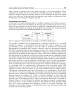
2.2 Characterization
In the present study, we used the higher-order local autocorrelational function (Otsu &
Kurita, 1998). The characteristics defined using the following expression were calculated
with respect to the reference point and its vicinity:
³
drarfarfrfaaax
NN
N
)()()(),,,(
121
ᇫ
(2)
Here, x
N
is the correlational function in the vicinity of the point r in dimension N. Since the
pixels around the object point are important when a recorded image is generally used as the
processing object, the factor N was limited up to the second order in the present study.
When excluding the equivalent terms due to parallel translation, x
N
is possibly expressed
using 25 types of characteristic quantities, as shown in Fig.5. However, patterns M1 through
M5 should be normalized since they have a smaller scale than the characteristic quantities of
patterns M6 and thereafter. By further multiplying the pixel values of the reference point for
patterns M2 through M5 and by multiplying the square of the pixel value of the reference
point for pattern M1, a good agreement with the other characteristic quantities was obtained.
In the present study, an image was divided into 64 sections in total – 8 x 8 each in the
vertical and lateral directions - and the respective divided images were represented by 25
types of characteristic quantities using the higher-order local autocorrelational function.
Manner of protrusion of the thumb
Curvature of
the coxa of
four fingers
310 Humanoid Robots, New Developments
Therefore, a single image is described using the characteristic quantities of 25 patterns x 64
divided sections. The image characteristics of the CG hand and the joint angle data were
paired as a set for preparing the database.
Fig. 5. Patterns of the higher-order local autocorrelational function.
2.3 Self-organization of the database
If the database prepared in the preceding sections is directly used for searching, it increases
the search time together with a larger database. Hence, we intend to narrow the search
space by clustering data with similar characteristics in the database. For example, sorting by
using a dichotomizing search may be feasible for ordinary data; however, in the case where
the characteristics range over multiple dimensions, a limitation is that the number of
searches during a retrieval becomes the same as that in the total search. Therefore, we
constructed a database using Kohonen’s SOM (Kohonen, 1988).
Each database entry has a joint angle and a number of image characteristics; however, only
the image characteristics are used in the search during estimation. There is a possibility that
there exist data that have similar characteristics but significantly different joint angles; such
data may be included in the same class if the classification is made on the basis of the
characteristics during the self-organization of the database. On the other hand, there also
exist data having significantly different characteristics, although the joint angles are similar.
Therefore, we performed self-organization for both these types of data and conducted
preliminary experiments; the obtained results are listed in Table 1. The mean value of the
errors and the standard deviation are the values for the middle finger. The data for the other
fingers are omitted from the table since they exhibited similar tendencies. Degree is used as
the unit of the mean value of the errors and the standard deviation. As shown in the table,
the case of self-organization on the basis of characteristics yielded better results.
Consequently, we performed data clustering using self-organization on the basis of
characteristics in the present study.
processing time [ms] mean error [degree] standard deviation
joint angle 0.842 0.792 6.576
characteristics 0.764 0.373 5.565
Table 1. Performance of self-organization on the basis of joint angles and characteristics in
the preliminary experiment.
Copycat Hand - Robot Hand Generating Imitative Behaviour at High Speed and with High Accuracy 311
First, we prepared classes having the representative angle, representative number of
characteristics and neighbourhood class information as classes in the initial period. For the
initial angles and the number of characteristics, random numbers in the range of 0 to 1 were
used. With regard to the neighbourhood class information, we calculated the distance
between classes in the angles by using the Euclidean distance and determined classes close
to one another in this distance as neighbouring classes; this information was retained as the
class number. Although the number of neighbouring classes depends on the scale of the
database and the processing performance of the PC, we studied it heuristically in this
experiment, and determined classes up to that close to the eighth as the neighbour classes.
Next, we calculated the distance in the characteristics between the data and the classes and
selected the closest class by using the data in a secondary database. This class will hereafter
be referred to as the closest neighbour class. Moreover, the used date will be considered as
those belonging to the closest neighbour class. The representative angle and representative
number of characteristics of the closest neighbour class were renewed by using the
expression below so that they may be placed closer to the data.
)(
)(
rjijijij
rjijijij
DFCFCFCF
DACACACA
D
D
(3)
where CA
ij
denotes the representative angle j of class i; DA
rj
, the angle j of data r; CF
ij
, the
representative number of characteristics j of class i; DF
rj
, the representative number of
characteristics j of data r; and a, the coefficient of learning.
In this experiment, a was heuristically determined as 0.0001. Next, a similar renewal was
also made in the classes included in the neighbour class information of the closest neighbour
class. However, their coefficient of learning was set to a value lower than that of the closest
neighbour class. In the present study, it was heuristically selected as 0.01. This was applied
to all the data in the primary database. In order to perform self-organization, the
abovementioned operation was repeated until there was almost no change in the
representative angle and the representative number of characteristics of the class.
Narrowing and acceleration of the search process can be realized to some extent, even if the
database is used without self-organization. However, if such a database is used, dispersion
is observed in the amount of data included in each class, thereby inducing dispersion in the
processing time. Therefore, we intended to avoid the lack of uniformity in the processing
time by introducing an algorithm for self-multiplication and self-extinction during self-
organization. After selecting the class of adherence for all the data, we duplicate the classes
that contain an amount of data exceeding 1.5 times the ideal amount. In addition, we deleted
the classes containing an amount of data no more than one-half the ideal amount of data.
Therefore, the amount of data belonging to each class was maintained within a certain range
without significant dispersion, and the processing time was maintained within a certain
limit, irrespective of the data in the class that was used for searching during the estimation.
In case the algorithm for self-multiplication and self-extinction is introduced, a change is
produced in the relationships among the classes, which remains unchanged in ordinary self-
organization, making it necessary to redefine the relationships among the classes. Therefore,
we newly prepared the neighbour class information by a method similar to that used during
initialization in which we duplicated and deleted the classes.
Estimations made by using a database obtained in this manner can considerably increase the
search speed as compared to the complete search of ordinary data. However, considering
further increases in the database and acceleration of the searches, the database clustering was
312 Humanoid Robots, New Developments
performed not only in a single layer but also in multiple layers. Fig. 6 shows the schematic
structure of the multiple layers. The class obtained with the aforementioned processing is
defined as the second-layer class and is considered as data. A third-layer class is prepared by
clustering the second-layer classes as the data. The third-layer class is prepared by following
the same procedure as that used in the preparation of the second-layer class. Further, a fourth-
layer class is prepared by clustering the third-layer classes. The lesser the amount of data in
one class (or the number of classes in the lower layers), the higher the layer in which clustering
can be performed. However, to absorb the dispersion of data, etc., it is preferable to prepare
classes having an amount of data with a certain volume. Table 2 lists the results of the
preliminary experiment in which clustering was performed by setting the amount of data in a
class at 5, 10 and 20. Although the search time is reduced if the clustering is performed with a
small amount of data, the estimation accuracy also reduces accordingly; therefore, we set an
ideal amount of data as 10 in the present study as a trade-off between the two parameters.
The clustered database obtained using the abovementioned operation was termed as a
tertiary database. This tertiary database will hereafter be simply referred to as the database.
In this system, we finally constructed a database comprising 5, 10 and 10 classes in order
from the upper layers, where each class has approximately 10 data items.
Fig. 6. Schematic structure of a database with multiple layers.
processing time [ms] mean error [degree] standard deviation
5 0.656 -0.035 5.868
10 0.764 0.373 5.565
20 1.086 0.145 5.400
Table 2. Performance according to the amount of data in a class in the preliminary
experiment.
2.4 Search of similar images
During estimation, sequential images were acquired using a high-speed camera. In a manner
similar to the preparation of the database, image processing techniques were applied to these
images to obtain their characteristic quantities. By comparing each quantity with that in the
database by means of a processing technique described later, the joint angle information that
formed a pair with the most similar image were defined as each result was estimated.
To estimate the similarity at the first search, the distance was calculated by using the
characteristic quantity for all classes in the database. The calculation was performed by
simply using the Euclidean distance that is derived using the expression below:
Copycat Hand - Robot Hand Generating Imitative Behaviour at High Speed and with High Accuracy 313
¦
n
i
tirir
xxE
*25
1
2
)( (4)
Here, both x
ri
and x
ti
are characteristic quantities i with the higher-order local autocorrelational
functions of the class r and at the time t, respectively. The class that minimizes E
r
was selected as
the most vicinal class at time t. With respect to the affiliated data of the most vicinal class and all
the vicinal classes of the most vicinal class, the distances from the characteristic quantities
obtained from the image were calculated using expression (4). At each instance, the angle of the
data with the shortest distance was regarded as the estimated angle. From the second search, the
distance was not calculated by using the characteristic quantity for all the classes in the database.
Instead, only the vicinal classes of the most vicinal class and the affiliated data were selected as
the candidates for the search according to the histories at t-1, as shown in Fig.7.
(a) at first search: all classes are candidates for the search.
(b) from second search, the vicinal classes of the most vicinal class are candidates.
(c) if the result moves to and affiliates with another class,
(d) then, the search space and candidate classes moves.
Fig. 7. Differences in the search spaces between the first search and the succeeding searches.
314 Humanoid Robots, New Developments
3. Experiment of posture estimation
3.1 Methods and procedures
In order to verify the effectiveness of this system, the actual images were subjected to
experimental estimation. A subject held up a hand at a position approximately 1 m in front
of the high-speed camera and moved the fingers freely provided the palm faced the camera.
A slight motion of the hand was allowed in all the directions provided the hand was within
the field angle of the camera. We employed a PC (CPU: Pentium 4, 2.8 GHz; main memory:
512 MB) and a monochromatic high-speed camera (ES-310/T manufactured by MEGAPLUS
Inc.) in the experiments.
3.2 Results and discussions
Fig.8 shows the examples of the estimation. Each estimated result plotted using the
wireframe model was superimposed on the actual image of a hand. It is evident that the
finger angles have possibly been estimated with a high precision when the hand and fingers
were continuously moved. It was verified that the estimation could be performed, provided
the hand image did not blend into the background, even if the illuminating environment
was changed.
Fig. 8. Captured hand images and the results of the hand posture estimation.
For the purpose of a quantitative assessment of the system, the measured and estimated
values have to be compared. However, in an ordinary environment using this system, it is
impossible to acquire the measured values of the joint angle information from the human
hand and fingers moving in front of the camera. Consequently, we performed the
estimation experiment by wearing the data glove and a white glove above it. The results
are shown in Fig.9, which reveals the angular data measured using the data glove and the
estimated results. Fig.9(a) shows the interphalangeal (IP) joint of the thumb; Fig.9(b), the
abduction between the middle and ring fingers; and Fig.9(c), the proximal interphalangeal
(PIP) joint of the middle finger. The state where the joint is unfolded was set as 180
degrees. The system at this time operates at more than 150 fps and thus enables realtime
estimation.
Copycat Hand - Robot Hand Generating Imitative Behaviour at High Speed and with High Accuracy 315
Fig. 9. Examples of the joint angle data measured using the data glove and the estimated
results.
As evident from the figure, the standard deviation of the errors in the estimated angles was
4.51 degrees when we avoided the fluorescent light and used the angular data obtained by
means of the data glove as the actual values; the results obtained did not have highly precise
numerical values. We observed a trend of poor estimations, particularly for parts with little
variation in the image (for example, the shape of the rock in the rock-paper-scissors game)
against the angular variation. This may be expected, considering that a human is performing
the figure estimation. In other words, we can hardly observe any difference visually for an
angular difference of 10 degrees when each finger has a difference of 10 degrees. Therefore,
the errors in this system, which conducts estimation on the basis of the camera image, may
be considered as being within the allowable range. On the contrary, it can be observed from
this figure that highly precise estimations are made in the region where visual differences
are observed, namely, where the image changes significantly with the angular variations
and where it is located in between the flexion and the extension.
GUVKO CVKQPCPING
O GCUWTGFCPING
GUVKO CVKQPCPING
O GCUWTGFCPING
GUVKO CVKQPCPING
O GCUWTGFCPING
Time [s]
J o i n t a n g l e [
d
e g
r
e e ]
(a)
(b)
(c)
316 Humanoid Robots, New Developments
Next, the comparative experiments were conducted. The difference between the previous
experiment and these comparative experiments is that the hand position agrees with or
closely resembles the database image since the object for estimation is set by selecting the
CG hand image from the database. Consequently, we can determine the expected
improvement in the estimating precision when the processing for positioning the input
image is integrated into this system. The standard deviation of the errors when estimating
the object was set to 2.86 degrees by selecting the CG image from the database, thus
allowing very high-precision estimation. It is expected that the estimation error can be
reduced to this extent in the future by integrating the processing for correcting the position
into this system. Moreover, the processing time for the search, except for the image
processing, is 0.69 ms per image. From the viewpoint of precision and processing speed, the
effectiveness of the multi-step search using the self-organized database has been proved.
As mentioned above, the estimation error for unknown input images had a standard
deviation of 4.51 degrees. Since this is an image processing system, small variations in the
finger joints in the rock state of the rock-paper-scissors game will definitely exhibit a
minimal difference in the appearance; these differences will numerically appear as a large
error in the estimation. However, this error possibly contains calibration errors arising from
the use of the data glove, as well as the errors caused by slight differences in the thickness,
colour, or texture of the data glove covered with the white glove. Therefore, the output of
the data glove or the actual value of the quantitative assessment requires calibration
between the strain gauge output and the finger joint value whenever the glove is worn since
the joint angle is calculated from a strain gauge worn on the glove. No such calibration
standards exist, particularly for the state in which the finger is extended; therefore, the
measured angle can be easily different from the indicated value. Even when the estimation
is newly calibrated, it is possible that the state of calibration may be different in each
experiment. On the other hand, it is not necessary to apply calibration to the second
experiment that selects the CG hand image from the database. It is highly possible that this
influences the standard deviation value of 4.51 degrees; therefore, it is possible to consider
that the standard deviation of the errors lies between 4.51 and 2.86 degrees even if the
system has not been subjected to corrective processing for the hand position.
The scheme of the present study allows you to add new data even without understanding
the system. Another advantage is that the addition of new data does not require a long time
since it is unnecessary to reorganize the database even when several new data items are
added; this is because the database can sequentially self-organize itself by using the
algorithm for self-multiplication and self-extinction of database classes. Furthermore, it is
possible to search the neighbouring classes having angular similarities since each class
possesses information about the vicinal classes in this system. This fact can also be regarded
as the best fit for estimating the posture of a physical object that causes successive temporal
angular variations, such as estimating the posture of the human hand. We attempted to
carry out the hand posture estimation when the hand is rotated, although the number of
trials was inadequate. Fig.10 shows an example of the result, which suggests that our system
functions when a subject is in front of the camera and is rotating his/her hand. A subject can
also swing the forearm, and our system can effectively estimate the shape of the fingers, as
shown in Fig.11.
The image information and the joint angle information are paired in the database in our
system. Once we output the results of the hand posture estimation to a robot hand, the robot
can reproduce the same motions as those of the fingers of a human being and mimic them.
Copycat Hand - Robot Hand Generating Imitative Behaviour at High Speed and with High Accuracy 317
Fig.12 shows a dexterous robot hand (Hoshino & Kawabuchi, 2005) imitating the human
hand motions without any sensors attached to it. We refer to this integrated system as the
“copycat hand”. This system can generate imitative behaviours of the hand because the
hand posture estimation system performs calculations at high speeds and with high
accuracy.
Fig. 10. An example of hand posture estimation using the rotating motion of the wrist.
Fig. 11. Examples of the estimation when a subject is swinging his/her forearm.
Fig. 12. The copycat hand can ape and imitate human hand motions at high speeds and with
high accuracy.
4. Conclusion
To realize a robot hand capable of instantly imitating human actions, high speed, high
accuracy and uniform processing time in the hand posture estimation are essential.
Therefore, in the present study, we have developed a method that enables the searching of
similar images at high speeds and with high accuracy and the search involves uniform
processing time, even in the case where a large-scale database is used. This is achieved by
(1) clustering databases having approximately uniform amounts of data using self-
organization, including self-multiplication and self-extinction and (2) by collating the input
images with the data in the database by means of the low-order image characteristics, while
narrowing the search space in accordance with the past history.
In the preliminary construction of the database, we generated CG images of the hand by
measuring the joint angles using a data glove and interpolating them; furthermore, we
318 Humanoid Robots, New Developments
extracted the contours, image characteristics and the characteristics that change only in the
hand shape, irrespective of the environmental light or skin colour. The image was divided
into several images and was converted into a number of characteristics by using the high-
order local autocorrelation function; the image was then saved in the database in a state
paired with the joint angle data obtained from a data glove. By clustering this database
using self-organization depending on the number of characteristics and by the self-
organization of classes in multiple stages, a multistage search was enabled using the
representative numbers of classes in several layers. Moreover, by incorporating self-
multiplication and self-extinction algorithms, we achieved a unification of the amount of
data belonging to each class as well as the number of classes in the lower layers to avoid the
dispersion of the search time in the classes.
The input image at the time of an actual estimation of the hand finger shape was subjected
to various types of image processing techniques in the same manner as that at the time of
construction of the database, and it was converted into a number of characteristics. The
distance from the number of characteristics obtained from the picture was calculated by
using a representative number of characteristics. Classes at close distances were selected as
candidate classes for the estimated angle, and a similar distance calculation was also
performed in the classes in each layer belonging to a candidate class for the estimated angle.
Among the respective data belonging to the candidate classes for the estimated angle in the
lowest class, the angle data of the data with the closest distance between the number of
characteristics was considered as the estimation result. Furthermore, for the selection of a
candidate class, we attempted to reduce the search space by using the previous estimation
results and the neighbour information.
By estimating the sequential images of the finger shape by using this method, we
successfully realized a process involving a joint angle estimation error within several
degrees, a processing time of 150 - 160 fps, and an operating time without dispersion by
using a PC having a CPU clock frequency of 2.8 GHz and a memory capacity of 512 MB.
Since the image information and the joint angle information are paired in the database, the
system could reproduce the same actions as those of the fingers of a human being by means
of a robot without any time delay by outputting the estimation results to the robot hand.
5. Acknowledgement
This work is partly supported by Proposal-Oriented Research Promotion Program
(PRESTO) of Japan Science and Technology Agency (JST) and Solution-Oriented Research
for Science and Technology (SORST) project of JST.
6. References
Athitos, V. & Scarloff, S. (2002). An appearance-based framework for 3D hand shape
classification and camera viewpoint estimation, Proc. Automatic Face and Gesture
Recognition, pp.40-45
Bernardin, K.; Ogawara, K.; Ikeuchi, K. & Dillmann, R. (2005). A sensor fusion approach for
recognizing continuous human grasping sequences using Hidden Markov Models,
IEEE Transactions on Robotics, Vol.21, No.1, pp.47-57
Gallese, V.; Fadiga, L.; Fogassi, L. & Rizzolatti, G. (1996). Action recognition in the premotor
cortex, Brain, Vol.119, pp.593-60
Copycat Hand - Robot Hand Generating Imitative Behaviour at High Speed and with High Accuracy 319
Hoshino, K. & Tanimoto, T. (2005). Real time search for similar hand images from database
for robotic hand control, IEICE Transactions on Fundamentals of Electronics,
Communications and Computer Sciences, Vol.E88-A, No.10, pp.2514-2520
Hoshino, K. & Tanimoto, T. (2006). Method for driving robot, United Kingdom Patent
Application No.0611135.5, (PCT/JP2004/016968)
Hoshino, K. & Kawabuchi, I. (2005). Pinching at finger tips for humanoid robot hand, Journal
of Robotics and Mechatronics, Vol.17, No.6, pp.655-663
Hoshino, K. & Kawabuchi, I. (2006). Hobot hand, U.S.A. Patent Application No.10/599510,
(PCT/JP2005/6403)
Kameda, Y. & Minoh, M. (1996). A human motion estimation method using 3-successive
video frames, Proc. Virtual Systems and Multimedia, pp.135-140
Kohonen, T. (1988). The neural phonetic typewriter, IEEE computer, Vol.21, No.3, pp.11-22
Lu, S.; Metaxas, D.; Samaras, D. & Oliensis, J. (2003). Using multiple cues for hand tracking
and model refinement, Proc. CVPR2003, Vol.2, pp.443-450
Otsu, N. & Kurita, T. (1998). A new scheme for practical, flexible and intelligent vision
systems, Proc. IAPR. Workshop on Computer Vision, pp.431-435
Rehg, J. M. & Kanade, T. (1994). Visual tracking of high DOF articulated structures: an
application to human hand tracking, Proc. European Conf. Computer Vision, pp.35-46
Rizzolatti, G.; Fadiga, L.; Gallese, V. & Fogassi, L. (1996). Premotor cortex and the
recognition of motor actions, Cognitive Brain Research, Vol.3, pp.131-141
Appendix: Composition of the humanoid robot hand
(Hoshino & Kawabuchi, 2005; 2006)
As compared to walking, the degree of freedom (DOF) assigned to manipulation functions
and to fingers is extremely low. The functions of the hands are mostly limited to grasping
and holding an object and pushing a lever up and down. The robot hand itself would tend
to become larger and heavier and it would be almost impossible to design a slender and
light-weight robot if currently available motors and reduction gears are used with a number
of DOFs equivalent to that of the human hand. It is important to determine where and how
to implement the minimum number of DOFs in a robot hand.
We have designed the first prototype of a dexterous robot hand. The length from the
fingertip to the wrist is approximately 185 mm and the mass of the device is 430 g, which
includes mechanical elements such as motors with encoders and reduction gears without
electrical instrumentation such as motor control amplifiers, additive sensors, or cables for
external connection.
Fig.13 shows two examples of generating movements involved in Japanese sign language. In
the case of the numeral 2, the index finger and the middle finger should be stretched during
abduction and pass through a clearance generated by the thumb. Generating the numeral 30
involves a difficulty. A ring is formed by the thumb and the fourth finger and the other
three fingers are stretched while exhibiting abduction and then bent to a suitable angle. As
for the two examples generated by this system, movements were carried out promptly while
maintaining an appropriate accuracy in order to facilitate a reasonable judgment of the
numerals created by using the sign language. The time duration of the movement is slightly
over 1 s for the numeral 2 and approximately 2 s for the numeral 30.
An important function for the robot hand is picking up small, thin, or fragile items using
only the fingertips. This capability is equally or even more important than the ability to
320 Humanoid Robots, New Developments
securely grasp a heavy object. Therefore, we designed a second prototype focusing on the
terminal joint of the fingers and the structure of the thumb.
Fig. 13. Examples of the sign language movements.
As an independent DOF, we implemented a small motor at every fingertip joint, namely at
distal interphalangeal (DIP) joints of four fingers and interphalangeal (IP) joint of the thumb.
The mass of the motor is approximately 10 g with a gear. Although the maximum motor
torque is very small (0.5 Nmm), the maximum fingertip force is 2 N because of the high-
speed reduction ratio and the short distance between the joint and the fingertip, which
provides sufficient force for picking up an object. Moreover, it has a wide movable range.
Each fingertip joint can bend inward as well as outward, which, for instance, enables the
robot hand to stably pick up a business card on a desk.
We also added a twisting mechanism to the thumb. When the tips of the thumb and fingers
touch, the contact is at the fingertip and the thumb pads; however, this may not provide a
sufficient contact with the other fingertip pads since the thumb cannot twist to make this
contact. The human hand has soft skin and padding at the fingertips and the high control of
motion and force at the fingertips enables stable pinching even if the finger pads are not in
complete mutual contact. However, we expect that the fingertip force produced by the
terminal joint drive at the tip of the two finger groups will act in opposite directions at the
same point, implying that the two fingertips will oppose each other exactly at the pad.
Fig.14 shows the snapshots of the performance of the second type of robot hand, which
repeated the series of movements and stably pinched the business card. The mass of the
hand is approximately 500 g and the length from the fingertip to the wrist is approximately
185 mm, which are almost equivalent to those of the human hand.
Fig. 14. Snapshots of the robot hand handling a business card using two or three fingers.
19
Energy-Efficient Walking for Biped Robot
Using Self-Excited Mechanism and
Optimal Trajectory Planning
Qingjiu Huang & Kyosuke Ono
Tokyo Institute of Technoligy, Japan
1. Introduction
Recently, a lot of researches which aim at realization of dynamic biped walking are being
performed. There is Honda's ASIMO as a representative of researches of humanoid robots.
ASIMO has joints of many degrees of freedom that are near to a human being, high
environment adaptability and robustness, and can do various performances. However, it
needs many sensors, complicated control, and walks with bending a knee joint to keep the
position of a centre of gravity constant. Therefore, it walks unnaturally and consumes much
energy.
On the other hand, McGeer performed the research of passive dynamic walking from the
aspect of that it is natural motion in a gravitational field (McGeer, T., 1990). This robot
which could go down incline only using potential energy was developed and realized the
energy-efficient walking. However, it needs incline, and its applied range is small because
it has no actuator. Therefore, the researches that aimed at energy-efficient biped walking
on level ground have been performed. S.H.Collins exploited the robot which had
actuators at only ankles (Collins, S. H. & Ruina A., 2005). M.Wisse exploited the robot
which used pneumatic actuators (Wisse, M. & Frankenhuyzen, J. van, 2003). Ono
exploited the self-excitation drive type robot which had an actuator only at hip joint (Ono,
K. et al, 2001); (Ono, K. et al, 2004); (Kaneko, Y. & Ono K., 2006). And then, Osuka and
Asano performed the level ground walking from a point of view to mechanical energy for
joints which is the same with the energy consumed of passiveness walk (Osuka, K. et al,
2004); (Asano, F. et al, 2004). These biped robot's studies used the technique of the passive
dynamic walking which used inertia and gravity positively by decreasing the number of
actuators as much as possible. However, in order to adapt the unknown ground, the
biped robot needs actuators to improve the environment adaptability and robustness.
Here, Ono proposed the optimal trajectory planning method based on a function
approximation method to realize an energy-efficient walking of the biped robot with
actuators similar to a passive dynamic walking (Imadu, A. & Ono, K. 1998); (Ono, K. &
Liu, R., 2001); (Ono, K. & Liu, R., 2002); (Peng, C. & Ono K., 2003). Furthermore, Huang
and Hase verified the optimal trajectory planning method for energy-efficient biped
walking by experiment, and proposed the inequality state constraint to obtain better
solution which is desirable posture in the intermediate time of the walking period (Hase,
T. & Huang, Q., 2005); (Huang, Q. & Hase, T., 2006); (Hase, T., et al., 2006).
322 Humanoid Robots, New Developments
In this chapter, we introduce the newest researches on energy-efficient walking of the biped
robot for level ground form two viewpoints, one is semi-passive dynamic walking with only
hip actuator using self-excited mechanism, another is active walking with actuators using
optimal trajectory planning.
The chapter is organized as follows. In section 2, the self-excited walking of a four-link
biped robot and the self-excitation control algorithm enables the robot to walk on level
ground by numerical simulation and experiment will be introduced. In section 3, we aim at
realizing an energy-efficient walking of the four-link biped robot with actuators similar to a
passive dynamic walking. An optimal trajectory planning method based on a function
approximation method applied to a biped walking robot will be shown. And then, we use
the inequality state constraint in the intermediate time and restrict the range of joint angles.
In this way, a better solution which is desirable posture in the intermediate time can be
obtained. Furthermore, in section 4, with “Specific Cost”, we show that the biped walking
with the above two methods have more efficient energy than the other methods which use
geared motors. Finally, the conclusions will be presented in section 5.
2. Self-Excited Walking for Biped Mechanism
In this section, we introduce a study on the self-excited walking of a four-link biped
mechanism that proposed by Ono (Ono, K. et al, 2001). And then, we show that the self-
excitation control enables the three-degree-of-freedom planar biped model to walk on level
ground by numerical simulation. From the parameter study, it was found that stable
walking locomotion is possible over a wide range of feedback gain and link parameter
values and that the walking period is almost independent of the feedback gain. Various
characteristics of the self-excited walking of a biped mechanism were examined in relation
to leg length and length and mass ratios of the shank. Next, a biped mechanism was
manufactured similar to the analytical model. After parameter modification the authors
demonstrated that the biped robot can perform natural dynamic walking on a plane with a
0.8 degree inclination. The simulated results also agree with the experimental walking
locomotion.
2.1
Analytical Model of Biped Walking Robot and Kinetic Process
2.1.1 Features of Biped Locomotion and Possibility of Its Self-Excitation
Fig.1 shows a biped mechanism to be treated in this study. Here we focus only on the biped
locomotion in the sagittal plane. The biped mechanism does not have an upper body and
consists of only two legs that are connected in a series at the hip joint through a motor. Each
leg has a thigh and a shank connected at a passive knee joint that has a knee stopper. By the
knee stopper, an angle of the knee rotation is restricted like the human knee. The legs have
no feet, and the tip of the shank has a small roundness. The objective of this study is to make
the biped mechanism perform its inherent natural walking locomotion on level ground not
by gravitational force but by active energy through the hip motor.
The necessary conditions for the biped mechanism to be able to walk on level ground are as
follows: (1) The inverted pendulum motion for the support leg must synchronize with the
swing leg motion. (2) The swing leg should bend so that the tip does not touch the ground.
(3) The dissipated energy of the mechanism through collisions at the knee and the ground,
as well as friction at joints, should be supplied by the motor. (4) The knee of the support leg
Energy-Efficient Walking for Biped Robot Using
Self-Excited Mechanism and Optimal Trajectory Planning 323
should not be bent by the internal force of the knee stopper. (5) The synchronized motion
between the inverted pendulum motion of the support leg and the two-DOF pendulum
motion of the swing leg, as well as the balance of the input and output energy, should have
stable characteristics against small deviations from the synchronized motion.
Fig.1. Three-degree-of freedom walking mechanism on a sagittal plane (Ono, K. et al, 2001)
First we pay attention to the swing leg and try to generate a swing leg motion that can
satisfy the necessary conditions (2) and (3) by applying the self-excitation control to the
swing leg motion. Ono and Okada (Ono, K. & Okada, T., 1994) have already investigated
two kinds of self-excitation control of two-DOF vibration systems and showed that the Van
der Pol-type self-excitation can evoke natural modes of the original passive system, while
the asymmetrical stiffness matrix type can excite the anti-resonance mode that has a phase
shift of about 90 degrees between input and output positions.
The two-DOF pendulum of a swing leg has the first-order mode with an in-phase at each
joint and the second-order mode with an out-of-phase at each joint. Thus, it will be
impossible to generate a walking gait by applying the Van der Pol-type self-excitation. In
contrast, by means of the negative feedback from the shank joint angle
T
3
to the input
torque T at the thing joint, the system’s stiffness matrix becomes asymmetrical. Thus, the
swing motion would change so that the shank motion delays at about 90 degrees from the
thigh motion. Through this feedback, it is also expected that the kinetic energy of the swing
leg increases and that the reaction torque (=T) will make the support leg rotate in the
forward direction in a region where
T
3
> 0. The self-excitation of the swing leg based on
the asymmetrical matrix is explained in detail below.
2.1.2
Self-Excitation of the Swing Leg
Fig.2 depicts the two-DOF swing leg model whose first joint is stationary. To make Fig 2
compatible with Fig.3 (b), the upper and lower links are termed the second and third links,
respectively. To generate a swing motion like a swing leg, only the second joint is driven by
the torque T2, which is given by the negative position feedback of the form
324 Humanoid Robots, New Developments
T
Tk
23
. (1)
Fig.2. Analytical model of two-degree-of-freedom swing leg (Ono, K. et al, 2001)
From the fundamental study of the asymmetrical stiffness matrix-type self-excitation (Ono,
K. & Okada, T., 1994), it is known that damping plays an important role in inducing the self-
excited motion. Thus, the viscous rotary damper with coefficient
J
3
is applied to joint 3.
Taking Eq. (1) into account, the equation of motion for the two-DOF pendulum system is
written as
TT
T
T
TT
J
TTTJ T
TTTJ J T
T
TT
T
TT
ªº
ªº
«»
«»
«»
«»
¬¼
¬¼
ªºªº
«»«»
«»«»
¬¼¬¼
ªº
ªº
«»
«»
¬¼
¬¼
ᇫ
Imaml mal
mal I ma
mal
mal
ma ml g k
mag
cos
cos
sin( )
sin( )
sin
.
sin
22
22232 332 32
2
2
3
332 3 2 3 33
333232332
332 3 2 2 3 3 3
2
22 32 2 2
3
33 3 3
0
0
(2)
We note from Eq. (2) that the stiffness matrix of the system becomes asymmetrical because
of the feedback gain k.
To examine the value of k to excite a swing leg motion autonomously and the natural
frequency and mode at the threshold, Eq. (2) is linearized about
TT
23
0 . The linearized
equation of motion becomes
TJJT T
JJ T
TT
ªº
ªº ªº
ªº
ªº ªº
«»
«» «»
«»
«» «»
«»
«» «»
¬¼ ¬¼
¬¼
¬¼ ¬¼
¬¼
ᇫ
Imaml mal
ma ml g k
mag
mal I ma
.
22
22232 332 2 3 32 2
22 32
2
33 3
33
33
332 3 33
0
0
(3)
Putting
t
e
O
T
4
22
and
t
e
O
T
4
33
into Eq. (3), we have
OJO OJO
OJO OJO
ªº
4
ªº
«»
«»
4
«»
¬¼
¬¼
ᇫ
akak
aak
.
22
11 3 11 12 3 2
22
3
21 3 22 3 22
0 (4)
Energy-Efficient Walking for Biped Robot Using
Self-Excited Mechanism and Optimal Trajectory Planning 325
Where aImama
22
11 2 2 2 3 2
, aamaI
12 21 3 3 2
, aIma
2
22 3 3 3
,
kmamIg
11 2 2 3 2
,
kmag
22 2 3
.
From the condition that the determinant in Eq. (4) is zero, we can obtain the characteristic
equation of the linearized system of the form
OOOO
AAAAA.
432
01234
0 (5)
As k increases, one of the eigenvalues becomes unstable. At the boundary,
O
becomes an
imaginary number. Thus, putting
O
= i
Z
into Eq. (5), we can get the critical k value and the
natural frequency at the inst ability threshold.
Here we assume that both links are a uniform bar whose length is 0.4 m (
ll
23
), and the
mass is 2 kg (
mm
23
). For these link parameters, one of the natural modes becomes
unstable when k > 1.43 or k < -3.14. The natural frequency of the unstable swing motion at
k= 1.43 is 0.71 Hz, whereas that at k = -3.14 is 0.61 Hz. If the damping does not exist at joint 3,
one of the natural modes becomes unstable when 30.4 > K > 6.3. Note that the damping
coefficient
J
3
, however small it might be, can significantly reduce the critical k value.
Strangely enough, the magnitude of the damping coefficient
J
3
does not change the critical
k value and the natural frequency at the threshold. However, the damping coefficient value
slightly influences the natural mode of the unstable vibration. By putting the natural
frequency and k value into Eq. (4) , we found a swing motion such that the lower link delays
from the upper link are excited when k t 1.43. The magnitude and phase of 44
23
are
0.60 and 8.89 degrees, respectively, when
J
3
= 0.15 Nms/rad. As the unstable vibration
grows in magnitude and approaches a limit cycle, the phase of the
44
23
tends to be 90
degrees (Ono, K. & Okada, T., 1994).
2.2 Analytical Model of Biped Locomotion and Basic Equations
The next question is whether the biped mechanism, which combines the two-DOF swing leg
discussed in Section 2.1 and the single-DOF support leg, can generate a biped locomotion
that satisfies the conditions (1), (4), and (5). Since it is difficult to derive this solution
analytically, we numerically show that the nonlinear biped system excited by the
asymmetrical feedback exhibits a stable biped locomotion that satisfies the three conditions
as a limit cycle of the system.
Fig.3 (a) shows the representative postures of a biped mechanism during half of the period
of biped locomotion. From an aspect of the difference of the basic equation, one step process
can be divided into two phases: (1) from the start of the swing leg motion to the collision at
the knee (the first phase) and (2) from the knee collision to the touchdown of the straight
swing leg (the second phase). We assume that the change of the support leg to the swing leg
occurs instantly and that the end of the second phase is the beginning of the first phase. The
self-excitation feedback of (1) is applied only during the first phase. We assume that the
support leg is kept straight because of internal reaction torque at the knee for simplifying
the forward dynamic simulation. The validity of this assumption will be examined later.
Under the assumption of a straight support leg, the analytical model during the first phase
is represented as a three-DOF link system, as shown in Fig.3 (b). Viscous damping is applied
to the knee joint of the swing leg. The equation of motion in this system during the first
phase is written as
326 Humanoid Robots, New Developments
T
T
T
ªº
ªº
«»
«»
«»
«»
«»
«»
¬¼
«»
¬¼
MMM
MM
sym M
1
11 12 13
22 23 2
33
3
(6)
Where the elements
ij
M
,
ij
C , and
i
K of the matrices are shown in Appendix A. T2 is
feedback input torque given by Eq. (1).
(a) Two phases of biped walking (b) Three-DOF model
Fig.3. Analytical model of three-degree-of-freedom walking mechanism (Ono, K. et al, 2001)
When the shank becomes straight in line with the thigh at the end of the first phase, it is
assumed that the knee collision occurs plastically. From the assumption of conservation of
momentum and angular momentum before and after the knee collision, angular velocities
after the knee collision are calculated from the condition
TT
23
and the equation of the form
>@
TT
T
TTTW
T
TT W
ªº
ªº
«»
«»
«»
«»
«»
«»
«»
«»
«»
¬¼
¬¼
f
Mf
f
,
,
,
111
1
1
2222
3
333
, (7)
Where the elements of the matrix [M] are the same as
ij
M
in Eq. (6) .
f
1
,
f
2
, and
f
3
are
presented in Appendix B.
W
is the moment impulse at the knee.
During the second phase, the biped system can be regarded as a two-DOF link system. Thus,
the basic equation becomes
TT
T
T
TT
TTTT
TTT T
T
TT
T
TT
ªº
ªº
«»
«»
«»
«»
¬¼
¬¼
ªºªº
«»«»
«»«»
¬¼¬¼
ªº
ªº
«»
«»
¬¼
¬¼
ᇫ
Ima ml mal
mal I ma
mal
mal
ma ml g
mag
cos
cos
sin( )
sin( )
sin
.
sin
22
11 21 221 3 2
2
2
3
221 2 1 2 22
221 2 1 2 2
221 2 1 1 3
1
11 21 1 1
2
22 2 2
0
0
0
0
0
(8)
Energy-Efficient Walking for Biped Robot Using
Self-Excited Mechanism and Optimal Trajectory Planning 327
We assume that the collision of the swing leg with the ground occurs plastically (the
translational velocity at the tip of the swing leg becomes zero) and that there is a sufficient
friction between the tip and the ground surface to prevent slippage. The angular velocities
of the links after the collision are derived from conservation laws of momentum and angular
momentum. They are calculated from Eq. (7) by putting
W
0.
To investigate the self-excited biped locomotion, a set of basic equations of (6), (7), and (8)
were numerically solved based on the fourth-order Runge-Kutta method. The standard
values of the link parameters used in the calculation are shown in Table 1. The values of
mass and moment of inertia were calculated assuming uniform mass distribution along the
link. Since the magnitude of the damping coefficient scarcely influences the biped gait,
.
J
3
015Nms/rad was used in the calculation.
Link1 Link2 Link3
m
i
mass [kg] 4.0 2.0 2.0
I
i
length [kgm
2
]
0.21 0.027 0.027
l
i
Moment of inertia [m] 0.80 0.40 0.40
a
i
Offset of mass center [m] 0.40 0.20 0.20
Table 1. Link Parameter Values Used for Simulation Study (Ono, K. et al, 2001).
2.3 Simulation Results and Characteristics of Self-Excited Walking
In this simulation, we assumed that the support leg is kept straight due to internal torque
during the first and second phases. To check whether the support leg can be lept straight by
the passive knee stopper, the internal torque at the knee of the two-DOF support leg model
was inversely calculated by using the calculated stable biped locomotion. Fig.4 plots the
angular displacement of
TS
1
,
T
2
, and
T
3
and the internal torques at the knees of the
support and swing legs, which are calculated from
T
1
,
T
2
, and
T
3
based on the inverse
dynamic analysis. The torque curve at
off
I
TT
d
12
0 . If the knee torque is negative, the
reaction torque exists at the knee stpooer so that the support leg can be regarded as a single-
DOF link. We observe that at the beginning of the first phase, the knee torque of the support
leg becomes positive for a short time of less than 0.1 s.
Then, we calculated the knee torque of the support leg by assuming an offset angle of
off
I
TT
23
2 degrees at the knee stopper. The calculated result is also shown in
Fig.4. We note that the knee torque of the support leg shifts downward and changes
to a negative value during the entire period. Moreover, it is seen from the negative
knee torque of the swing leg that the swing leg can be kept straight during the
secondphase.
In the numerical sumulation, steady biped locomotion can be obtained as a limit cycle for
the feedback gain value in a range of 4.8 Nm/rad
kdd 7.5 Nm/rad. When k is smaller than
4.8 Nm/rad, the initial step length gradually decreases and the biped mechanism falls down
forward. When k is larger than 7.5 Nm/rad, the step changes irregularly and the biped
mechanism falls down backwards because the swing leg is raised too high. Fig.5 shows the
walking period, average velocity, and efficiency as a function of feedback gain k. The
efficiency is defined as the ratio of average walking velocity to average input power, where
the average input power is given by
328 Humanoid Robots, New Developments
tt
tt
PTdt
tt
T
³
4
0
22
40
1
. (9)
Fig.4. Motion of legs and internal torque at knee during one step (Ono, K. et al, 2001).
Fig.5. Effect of feedback gain on walking period, velocity, and efficiency (Ono, K. et al,
2001).
We note from this figure that the walking period shows an almost constant value of 1.3 s
at any k value. This is because the self-excited biped locomotion is a natural motion
inherent in the biped system. On the other hand, the average velocity increases gradually
because of the increase in step length. However, the efficiency decreases with an increase
in the feedback gain k because the average input power increases more rapidly with an
increase in k. It is worthy to note that the average input power to generate biped
locomotion with a velocity of 0.28 m/s is only about 4 W (=0.28/0.07) at k = 6.0 Nm/rad.
If the additional movement of 0.6 m by feet during one period of 1.3 s is taken into
account, the natural walking velocity becomes 2.7 km/h. the natural walking period of an
adult with a 0.9 m leg height is 1.3 s (Yang 1994). Thus, it can be said that the calculated
results of the walking period and velocity are comparable with the natural walking of an
adult with a 0.8 leg height.
Energy-Efficient Walking for Biped Robot Using
Self-Excited Mechanism and Optimal Trajectory Planning 329
Validity of the self-excited walking stated above was confirmed experimentally (Ono, K.,
2001). Extensions of the self-excited walking to a biped with feet and bent knee walking
mode are described in (Ono, K., 2004) and (Kaneko, Y. & Ono K., 2006), respectively.
3. Energy-Efficient Trajectory Planning for Biped Walking Robot
In this section, we aim at realizing a energy-efficient walking of biped with actuators
similar to a passive dynamic walking. We suggested optimal trajectory planning method
based on a function approximation method, and applied for a biped walking robot
analytically. We obtained the solutions which made the square integral value of input
torque minimum. Until this point, we clarified the application of optimal trajectory
planning method for biped walking robots, but they did not constrain the clearance
between toe and ground at intermediate time of one period. As is generally known, it is
necessary to give the clearance between toe and ground in the intermediate time of one
step period. However, because there is the redundant degree of freedom by only
constraining the clearance with equality state constraint, the solutions of undesired
postures may be obtained. Therefore we suggest the optimal trajectory planning method
with inequality state constraint that can restrict the joint angles to the desired range in a
certain time. Concretely, we use inequality state constraint in the intermediate time and
restrict the range of joint angles and may obtain a better solution which is desirable
posture in the intermediate time.
With this method, we calculate optimal walking gait for biped with upper body mass. This
model is attached the same masses to the support leg and swing leg in forward direction.
And we examine the influence of installation position of the upper body mass.
And We perform a walking experiment by a prototype robot to inspect the effectiveness of
this method. At first, in order to realize a stable walking, we attach a sensor at a sole to
measure the time of grounding and compensate the error between reference trajectory and
experimental trajectory. And, we install adjustment masses to revise parameters of the
prototype robot. Furthermore, we use “Specific Cost” which shows energy consumption per
unit mass and per unit movement velocity for evaluation of energy efficiency in section 4.
By comparing the data of the other robots with this method, we show that our robot walks
more efficiently than the other robots which use geared motors.
3.1 Analytical Model of Biped Walking Robot and Kinetic Process
3.1.1 Analytical Model and Kinetic Process
Fig.6 shows the three link biped model used in this research. Link 1 is the support, link 2 is
the thigh, and link 3 is the shank. This model has upper body masses which is the same
masses attached to the support leg and swing leg in forward direction. Table.3 shows the
link parameters used in this analysis.
Table.2 shows symbols used in this paper (Hase, T.; Huang, Q. & Ono, K., 2006).
One step period is from Posture 1 to Posture 4 shown in Fig.7. State variables of Posture 4
are same as one of Posture 1. When it changes from Posture 3 to Posture 4, a collision
between toe and ground happens, and link parameters exchange. In Posture 3, the swing leg
collides with the ground, and becomes the support leg and the support leg leaves from the
ground and comes back to Posture 4 (Posture 1). Leg exchange is performed by perfectly
inelastic collision momentarily.
330 Humanoid Robots, New Developments
Symbols Description
m
i
i-th link mass
I
i
i -th link moment of inertia
l
i
i -th link length
a
i
Length between i-th joint and i-th link COG
b
i
Length between (i+1)-th joint and i-th link COG
m
d
Upper body mass
d
Length between upper body mass and hip joint
lj
i
i-th link absolute angle
ǂ
i
Offset angle between i-th link and i-th link COG from joint i
ǃ
i
Offset angle between i-th link and i-th link COG from joint (i+1)
x
i
x-coordinate of i-th link COG
y
i
y-coordinate of i-th link COG
g
Acceleration of gravity
u
i
i-th joint input torque
J
Performance function
LJ
i
Dummy variable used for inequality constraint
Dž
i
Clearance between toe and ground
p
i
i-th coefficient vector of basis function
h
i
i-th basis function
T
Period of one step
S
Length of ste
Table 2. Symbols used in this section (Hase T. & Huang, Q., 2005)
Fig.6. 3 link model with upper body mass (Hase T. & Huang, Q., 2005).
Energy-Efficient Walking for Biped Robot Using
Self-Excited Mechanism and Optimal Trajectory Planning 331
Link1 Link2 Link3
m
i
[kg] 4.2 1.2 1.2
I
i
[kgm
2
]
0.127 0.029 0.029
l
i
[m] 0.60 0.30 0.30
a
i
[m] 0.339 0.115 0.125
Table 3. Link parameters (Hase T. & Huang, Q., 2005).
Fig.7. Process of one step walking (Hase T. & Huang, Q., 2005).
Fig.8. Impulse for i-th link (Hase T. & Huang, Q., 2005).
3.1.2 Dynamic Equations and Analysis of Collision between Toe and Ground
By the analytical model shown in Fig.6, dynamic equations are lead as follows. We assumed
that there is no friction in each joint.
M
() C() K() u
TT TT T
2
(10)
When collision between toe and ground occurs, it is assumed that a momentum and angular
momentum of each link are conserved. Leg exchange happens shown as Fig.7.
Fig.8 shows impulse for
i-th link. "v
ix
", "v
iy
" is x, y ingredient of translation velocity of a
center of gravity of each link. "+" indicates the state just after the swing leg collides with the
ground, and "-" indicates the state just before that.
Using the conservation law of momentum and angular momentum, following equations
work out.
iix ix ix i x
iiy iy iy i y
ii i i i i i i
mv v P P
mv v P P
I
()
()
()
()
()aP(la)P
TT
°
°
®
°
uu
°
¯
1
1
1
(11)