Underwater Vehicles part 15 pot
Bạn đang xem bản rút gọn của tài liệu. Xem và tải ngay bản đầy đủ của tài liệu tại đây (5.38 MB, 34 trang )
Dynamic Modelling and Motion Control for Underwater Vehicles with Fins
549
4 3 2 1
3 2 1 0
2 1 0 -2
1 0 -1 -2
0 -1 -2 -3
Table 1. Control rules table
Generally, the function of sigmoid curve is given by
(
)
0.10.10.2 −+=
−kx
ey (31)
Then, the function of sigmoid curved surface is
(
)
(
)
0.10.10.2
21
−+=
−− ykxk
ez
(32)
Thus, the designed control model of S surface controller is
()
(
)
0.10.10.2
21
−+=
−− ekek
eu
(33)
where
e and
e
stand for the input information (error and the rate of error change, which are
normalized),
u is the control output which is the output force (normalized) in each
freedom, and
1
k
and
2
k
are the control parameters corresponding to error and rate of error
change respectively.
In equation (33), there are only two control parameters (
1
k and
2
k ) which S surface
controller need to adjust. It is important to note that S surface controller can not get the best
matching, whether adopting manual adjustment or adaptive adjustment. This is because
that the adjustment is global and local adjustment is not available. Therefore, parameter
adjustment is just the approximation of the system. After all, due to the complexity and
uncertainty of control object, any kind of approach has big approximation. Thus, the optimal
parameters
1
k and
2
k
are different due to different velocities.
Manual adjustment of control parameters can make the motion control of underwater
vehicle meet the demand in most cases. Response is more sensitive to small deviation but
vibrations easily occur when
1
k
and
2
k
are larger. Therefore, the initial values of
1
k
and
2
k
we choose are generally about 3.0. If the overshoot is large, we can reduce
1
k and increase
2
k simultaneously. By contrast, if the speed of convergence is slow, we can increase
1
k
and
reduce
2
k simultaneously.
The ocean current and unknown disturbances can be considered as fixed disturbance force
in a samlping period. Thus, we can eliminate the fixed deviation by adjusting the excursion
of S surface and the function of control model is
(
)
(
)
ueu
ekek
Δ0.10.10.2
21
+−+=
−−
(34)
where
uΔ is the value(normalized) of fixed disturbance force which is obtained through
adaptive manner. The adaptive manner is as follows:
Underwater Vehicles
550
a. Check whether the velocity of the vehicle is smaller than a preset threshold. If it is, go to
step b), if not, go to step c);
b.
Give the deviation value of this degree to a set array, at the same time, add 1 to the set
counter, when the very counter reaches the predefined value, go to step d);
c.
Shift each element in the array to the left by one, and at the meantime, decrease the
counter by 1, then go to step a);
d.
Weighted average the values of the array and the gained average deviation values are
obtained. Then these deviation values are used to compute the side-play amount of
control output, self-adapt the control output to eliminate fixed deviation, meanwhile,
set the counter to zero, turn to the next loop.
Thus, a simple and practical controller is constructed, which can meet the work requirement
in complicated ocean environment. However, the parameter adjustment of S surface
controller is completely by hand. We hope to adjust the parameters for the controller by
itself online, so we will present the self-learning algorithm the idea borrowed from BP
algorithm in neural networks.
3.2 Self-learning algorithm
Generally, we define a suitable error function using neural networks for reference, so we can
adjust the control parameters by BP algorithm on-line. As is known, an AUV has its own
motion will, which is very important for self-learning and will be discussed in detail in the
next section, so there is also an expected motion state. Namely, there is an expected control
output for S surface controller. Therefore, the error function is given by
2
)(
2
1
uuE
dp
−= (35)
where
d
u is the expected control output, and u is the last time output which can be
obtained by eqution (34) .
We can use gradient descent optimization method, i.e. use the gradient of
E
p
to adjust k
1
and
k
2
.
i
p
i
k
E
ηk
∂
∂
−=Δ (36)
where η is the learning ratio (
10
<
<
η ).
i
ekek
ekek
d
i
d
i
p
e
e
e
uu
k
u
uu
k
E
2
)1(
0.2
)()(
21
21
−−
−−
+
⋅−−=
∂
∂
⋅−−=
∂
∂
(37)
where
2,1=i
;
ee
=
1
; ee
=
2
Therefore,
1
k
and
2
k can be optimized by the following eqution.
i
ekek
ekek
diiii
e
e
e
uuηtkktktk ⋅
+
⋅−+=+=+
−−
−−
2
)1(
2
)()(Δ)()1(
21
21
(38)
We can get the expected speed by expected state programming. The expected control output
can be obtained by the following principles.
Dynamic Modelling and Motion Control for Underwater Vehicles with Fins
551
If the speed v is less than or equal to
d
v , then u is less than
d
u , and u needs to be
magnified. In the contrast, u needs to be reduced. The expected control output is given by
)( vvcuu
dd
−
⋅
+
=
(39)
where c is a proper positive constant. Therefore, S surface controller has the ability of self-
learning.
3.3 AUV motion will
As an intelligent system, the AUV has motion will to some degree. It knows the expected
speed and when and how to run and stop. The effect from environment changing is
secondary, and it can overcome the distubance by itself. Certainly, the obility to overcome
the distubance is not given by researchers, because they may not have the detailed
knowledge of the changing of environment. Howerver, the AUV motion will can be given
easily, because the artificial machine must reflect the human ideas. For example, when an
AUV runs from the current state to the objective state, how to get the expected
acceleration(motion will) can be considered synthetically by the power of thrusters, the
working requirement and the energy consumption. However, the active compensation to
various acting force (the reflective intelligence for achieving the motion will) will be
obtained from self-learning. This is the path which we should follow for the AUV motion
control (Peng, 1995).
The purpose of motion control is to drive the error
S and the error variance ratio V between
the current state and and the objective state to be zero. The pre-programming of control
output is given by
),(},,,,{
VSVa faaaaa
θψzyx
=
=
=
(40)
where the concrete form of
)(⋅f
can be given by synthetically consideration according to the
drive ability of the power system.
max
Paa = (41)
where
max
a is the AUV maximal acceleration, which lies on the drive ability of power system
and the vehicle mass.
P is given by
⎥
⎥
⎥
⎥
⎥
⎥
⎦
⎤
⎢
⎢
⎢
⎢
⎢
⎢
⎣
⎡
=
5
4
3
2
1
0
0
p
p
p
p
p
P
(42)
where
⎪
⎪
⎪
⎩
⎪
⎪
⎪
⎨
⎧
=
=
=
=
=
)2/tanh(
)2/tanh(
)2/tanh(
)2/tanh()/(
)2/tanh()/(
5
4
3
2
1
θ
ψ
z
xyxyy
xyxyx
pp
pp
pp
pppp
pppp
(43)
Underwater Vehicles
552
⎪
⎪
⎪
⎪
⎩
⎪
⎪
⎪
⎪
⎨
⎧
+=
−=
−=
−=
−=
−=
22
*
*
*
*
*
yxxy
θθθθ
ψψψψ
zzzz
yyyy
xxxx
ppp
VcSp
VcSp
VcSp
VcSp
VcSp
(44)
where
*
x
S ,
*
y
S ,
*
z
S ,
*
ψ
S ,
*
θ
S are difined as the traction distances in x ,
y
, z ,
ψ
, θ direction
given by
⎪
⎪
⎩
⎪
⎪
⎨
⎧
−≤−
−<<−
≥
=
)(
)(
)(
*
max
*
max
*
max
*
max
*
max
*
max
*
iii
iiii
iii
i
SSS
SSSS
SSS
S (45)
where =ix,
y
, z ,
ψ
, θ .
*
max
i
S and
i
c are undetermined coefficients, and
*
max
i
S are the
predefined maximal distances which are determined based on the AUV’s ability. We hope
that the maximal transfer speed
maxi
V
0
max
*
max
=−
iii
VcS (46)
As can be seen, we can not determine
*
max
i
S and
i
c by equation (46), so we define the other
constraint equation shown in equation (47).
()
()
⎪
⎪
⎪
⎩
⎪
⎪
⎪
⎨
⎧
=
′
=
>
⎟
⎟
⎟
⎟
⎠
⎞
⎜
⎜
⎜
⎜
⎝
⎛
⎟
⎠
⎞
⎜
⎝
⎛
−
′
+
−=
″
0
max
*
max
0max
t=t ,
,
exp1
2
1
ii
ii
iii
ii
VS
SS
tt
SSc
aS
(47)
Therefore, to all
0
tt > , 0>
i
S , and get smallest possible
0
tt
n
> . To all
n
tt > , we can obtain
ii
εS
<
(48)
where
i
ε is the state precision. The constraint condition is to reduce errors as well as drive
overshoot to zero.
4. Experiments
In this part, simulation and lake experiments have been conducted on WEILONG mini-AUV
for many times to verify the feasibility and superiority of the mathmetical modelling and
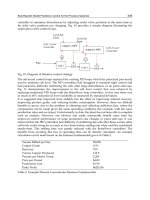
control method. The position errors of longitudinal control simulation are shown in Fig. 8.
Reference inputs are 5m, the velocity of current is 0 m/s, and the voltage of thrusters is
restricted by 2.5V. As can be seen, S surface control is feasible for the AUV motion control.
For the figure on the left,
0.8
1
=k
and 0.5
2
=k . Since the initial parameters are too big, there
is certain overshoot and concussion aroud the object state in S surface control. However, the
Dynamic Modelling and Motion Control for Underwater Vehicles with Fins
553
parameters are adjusted by self-learning in improved S surface control. The overshoot is
reduced and the balance (? Do you mean steady state) is achieved rapidly. For the figure on
the right,
0.3
1
=k
and 0.5
2
=k . The initial parameters are too small, so the rate of
convergence is too slow in S surface control. In improved S surface control, the rate of
convergence is picked up and the performance is improved greatly.
Field experiments are conducted in the lake. The experiments use the impoved S surface
control and the results are shown in Fig. 9 and Fig. 10. As there exits various disturbance
(such as wave and current), the result curves are not smooth enough. In yaw control
experiment, the action of the disturbances is greater than the acting force, so we can see
some concussions in Fig. 9. It needs to be explained in the depth control that there is no
response at the beginning of the experiment. The reason is the velocity of WEILONG mini-
AUV is very low and the fin effect is too small. In the computer simulation, we don’t use the
fins until the velocity reaches certain value.
a. k1=8.0, k2=5.0
-1
0
1
2
3
4
5
6
0 20406080100
t (0.25s)
position error (m)
S surface control
improved S surface control
b. k1=3.0, k2=5.0
-1
0
1
2
3
4
5
6
0 50 100 150 200 250
t (0.25s)
position error (m)
S surface control
improved S surface control
Fig. 8. Simulation results of longitudinal control
140
150
160
170
180
190
200
210
220
0 100 200 300 400 500 600 700 800
t (0.25s)
yaw (degree)
actual value
desired value
Fig. 9. Results of yaw control in lake experiments
Underwater Vehicles
554
-0.2
0
0.2
0.4
0.6
0.8
1
1.2
0 50 100 150 200 250
t (0.25s)
depth (m)
actual value
desired value
Fig. 10. Results of depth control in lake experiments
As can be seen, the control performance meets the requirement for the AUV motion control
by using improved S surface control. It has high response speed and good robustness to
various disturbances in field experiments.
5. Conclusion
This chapter concentrates on the problem of modeling and motion control for the AUVs
with fins. Firstly, we develop the motion equation in six-degree freedom and analyze the
force and hydrodynamic coefficients, especilly the fin effect. The feasibility and accuracy are
verified by comparing the results between at-sea experiments and simulation. The model is
applicable to most AUVs. Secondly, we present a simple and practical control method—S
surface control to achieve motion control for the AUVs with fins, and deduce the self-
learning algorithm using BP algorithm of neural networks for reference. Finally, the
experiment results verify the feasibility and the superiority of the mathmetical modelling
and control method.
6. Acknowledgements
The authors wish to thank all the researchers at the AUV Lab in Harbin Engineering
University without whom it would have been impossible to write this chapter. Specifically,
the authors would like to thank Professor Yuru Xu who is the subject leader of Naval
Architecture and Ocean Engineering in Harbin Engineering University and has been elected
as the member of Chinese Academy of Engineering since 2003. Moreover, the authors would
like to thank Pang Shuo who is an assistant professor of Embry-Riddle Aeronautical
University in USA.
Dynamic Modelling and Motion Control for Underwater Vehicles with Fins
555
7. References
Blidberg D.R. (1991). Autonomous underwater vehicles: a tool for the ocean, Unmanned
Systems, Vol. 9, No. 2, 10-15, 1991.
Xu Y.R.; Pang Y.J.; Gan Y. & Sun Y.S. (2006). AUV-state-of-the-art and prospect. CAAI
Transactions on Intelligent Systems, Vol.1, No.1, 9-16, September 2006.
Xu Y.R. & Xiao K. (2007). Technology development of autonomous ocean vehicle. Journal of
Automation, Vol. 33, No. 5, 518-521, 2007.
Conte G. & Serrani A. (1996). Modelling and simulation of underwater vehicles. Proceedings
of the 1996 IEEE International Symposium on Computer-Aided Control System Design,
pp. 62-67, Dearborn, Michigan, September 1996
Timothy P. (2001). Development of a Six-Degree of Freedom Simulation Model for the
REMUS Autonomous Underwater Vehicle: Oceans. MTS/IEEE Conference and
Exhibition, pp. 450-455, May 2001
Prestero T. J. (2001). Development of a six-degree of freedom simulation model for the
remus autonomous underwater vehicle. Proceedings of the OCEANS 2001
MTS/IEEE Conference and Exhibition, pp. 450-455, Honolulu, Hawaii, November
2001
Ridley P.; Fontan J. & Corke P. (2003). Submarine dynamic modeling. Proceedings of the
Australian Conference on Robotics and Automation, Brisbane, Australia, December
2003
Chang W.J.; Liu J.C. & Yu H.N. (2002). Mathematic model of the AUV motion control and
simulator. Ship Engineering, y, Vol.12, No.3, 58-60, September 2002.
Li Y.; Liu J.C. & Shen M.X.(2005). Dynamics model of underwater robot motion control in 6
degrees of freedom. Journal of Harbin Institute of Technology, Vol.12, No.4, 456-459,
December 2005.
Nahon M. (2006). A Simplified Dynamics Model for Autonomous Underwater Vehicles.
Journal of Ocean Technology, Vol. 1, No. 1, pp. 57-68, 2006
Silva J.; Terra B.; Martins R. & Sousa J. (2007). Modeling and Simulation of the LAUV
Autonomous Underwater Vehicle. Proceedings of the 13th IEEE IFAC International
Conference on Methods and Models in Automation and Robotics, pp. 713-718, Szczecin,
Poland, August 2007
Su Y.M.; Wan L. & Li Y. (2007). Development of a small autonomous underwater vehicle
controlled by thrusters and fins. Robot, Vol. 29, No. 2, 151-154, 2007.
Shi S.D. (1995). Submarine Maneuverability. National Defence Industry Press, Beijing.
Louis A.G. (2004). Design, modelling and control of an autonomous underwater
vehicle. Bachelor of engineering honours thesis, University of Western Australia,
2004.
Giuseppe C. (1999). Robust Nonlinear Motion Control for AUVs. IEEE Robotics & Automation
Magazine. pp. 33-38, May 1999
Peng L.; Lu Y.C. & Wan L. (1995). Neural network control of autonomous underwater
vehicles. Ocean Engineering, Vol.12, No.2, 38-46, December 1995.
Liu X.M. & Xu Y.R. (2001). S control of automatic underwater vehicles. Ocean Engineering,
Vol.19, No.3, 81-84, September 2001.
Underwater Vehicles
556
Liu J.C.; Yu H.N. & Xu Y.R. (2002). Improved S surface control algorithm for
underwater vehicles. Journal of Harbin Engineering University, Vol.23, No.1, 33-
36, March 2002.
29
Fundamentals of Underwater Vehicle Hardware
and Their Applications
Hiroshi Yoshida
Japan Agency for Marine-Earth Science and Technology
Japan
1. Introduction
The evolution of electrical and electronic engineering technology including nanotechnology
over the last several years has led to improvements in the development of mobile
underwater platforms or autonomous underwater vehicles (AUVs) enabling them to go
where tethered vehicles or manned vehicles have trouble reaching, such as under the ice,
other dangerous zones, and into the deepest depths. In order to survey the whole ocean
efficiently, the development of intelligent underwater vehicles will be one necessary
solution. For the development of practical intelligent underwater vehicles, designers need
cutting-edge fundamental devices incorporated into advanced underwater vehicles. Over
the past ten years, the underwater research and development team to which the author
belongs has developed five custom-made underwater vehicles: Urashima (Aoki 2001 & 2008),
UROV7k (Murashma 2004), MR-X1 (Yoshida 2004), PICASSO, and ABISMO.
Urashima is the prototype vehicle of a long cruising range AUV (LCAUV) powered by the
hybrid power source of a lithium-ion battery and a fuel cell. Urashima autonomously
travelled over 300 km for about 60 hours in 2005. The LCAUV aims to make surveys under
the arctic ice possible for distances of over 3000 km. The UROV7k is a tether cable-less ROV,
having its power source in its body like an AUV. The UROV7k was designed to dive up to
7000 m without large on-board equipment such as a cable winch, a traction winch or a
power generator. The MR-X1 is a middle-size prototype AUV for the test of modern control
methods and new hardware and for the development of new mission algorithms. The
plankton survey system development project named Plankton Investigatory Collaborating
Survey System Operon (PICASSO) project at the Japan Agency for Marine-earth Science and
TEChnology (JAMSTEC) aims to establish a multiple vehicle observation system for efficient
and innovative research on plankton. By using the ROV Kaiko, which was the deepest diving
ROV in the world, a number of novel bacteria were found from mud samples taken in the
Challenger Deep in the Mariana Trench (Takai, 1999). However, the lower vehicle of the
KAIKO system was lost when the secondary tether was sheared (Watanabe 2004). The most
important goal of the ABISMO system is to obtain mud samples from the Challenger Deep
in the Mariana Trench, because scientists still want uninterrupted access to the deepest parts
of the oceans using a vehicle equipped with sediment samplers. ABISMO consists of a
sampling station and a sediment probe. The station contains two types of bottom samplers.
One launches the probe to make a preliminary survey, launching the sampler to obtain a
sample.
Underwater Vehicles
558
Through the development of these vehicles, many improvements in fundamental devices for
underwater vehicles were made. In this chapter, firstly, hardware information on the key
devices needed to make cutting edge intelligent underwater vehicles are described. These
include new original devices: a small electrical-optical hybrid communication system, an
HDTV optical communication system, an inertial navigation system, buoyancy material for
the deepest depths, a thin cable with high-tensile strength, a USBL system, a broadcast class
HDTV camera system, an HDTV stereoscopic system, a high capacity lithium ion battery, a
high efficiency closed-cycle PEM fuel cell, and a prototype of an underwater
electromagnetic communication system. In the third section, we present attempts made for
data processing methods for autonomous control of underwater vehicles. Finally, the details
of the AUVs using the above-mentioned devices are given, including some of the sea trial
results.
2. Underwater vehicle hardware
2.1 Categories of unmanned underwater vehicles and their basic device components
Remotely operated vehicles (ROVs) and autonomous underwater vehicles (AUVs) are well-
known kinds of underwater vehicles. Recently, there are also newer categories of
underwater vehicles, untethered ROVs (UROVs) and hybrid ROVs (HROVs). UROVs (Aoki
et al., 1992) have the feature that the vehicle is only connected to its support ship via a long
thin optical fiber cable. The vehicle of an UROV system has its own power supply, in the
form of batteries - much like an AUV. An operator controls the vehicle in real-time and has
access to high quality real-time video images using high data rate optical communication
tools. UROVs have both the advantages of ROVs and AUVs. An HROV (Bowen et al., 2004),
one of which is under development at the Woods Hole Oceanographic Institution, is a single
vehicle that can perform two different, but related, missions. It refers to the vehicle's ability
to do scientific research while tethered to the ship, and also while swimming freely.
Traditionally, a separate vehicle is used to conduct long range surveys, while another
vehicle performs the close-up work and sampling. The HROV will simply transform
between its two modes of operation to accomplish both of these tasks. In this section, cutting
edge basic devices, except for those devices used for controlling vehicles and power sources,
are described.
a. Buoyancy Materials and Cables
These are fundamental devices for underwater vehicles. In extreme environments, such as in
the deepest depths, a developer should use special devices to match the mission. Full depth
buoyancy materials have been commercialized but they have never actually been used in
real situations at full ocean depth. The HROV project group at WHOI has chosen
SeaSpheres, produced by Deepsea Power & Light, as an alternative to syntactic foams made
from micro glass balloons. JAMSTEC has developed a new buoyancy material usable at full
ocean depth. The prototype was used in the ABISMO system and it successfully withstood a
10,300 m depth deployment in 2008. The specifications of the prototype are a crush pressure
of 56 MPa and a specific gravity of 0.63.
Tether cables for underwater vehicles are also a key device for successful development.
Many companies have produced underwater cables, except for cables rated for full depth.
Kyo (Kyo 1999) used a Kevlar fiber cable for the full depth vehicle Kaiko, but it was broken
during retrieval of the Kaiko vehicle in the face of an approaching typhoon (Watanabe 2004).
JAMSTEC thus started the development of a new cable using para-aramid fiber with a
Fundamentals of Underwater Vehicle Hardware and Their Applications
559
tensile strength of 350kg/mm
2
in 2005. This rod type aramid fiber does not concentrate
stress. The cable (φ20 mm x 160 m) consists of this aramid fiber, two coaxial cables, four
single wire cables for power lines, cable sheath, and resin. The cable is covered in
polypropylene. Specific gravity of the cable is around 1.3 and rupture strength is about 70
kN.
Fig. 1. A prototype of the full ocean depth buoyancy material (left) and the secondary cable
made from para-aramid fiber (right).
Thin fiber optic cable and spoolers are used for UROV and HROV systems. Traditional φ0.9
mm single mode fiber (Murashima 2004) or thinner fiber cable (Young 2006) is practically
used for underwater vehicles.
b. Lights and Cameras
For the observation of marine organisms, seafloor geology and underwater object
recognition, the selection and arrangement of lights and cameras are important. The
popularity of high definition television (HDTV) cameras and LED lights are causing an
increase in availability of underwater video. In addition to high quality camera imaging,
there are holographic cameras, laser scanning systems, acoustic imaging systems and so on.
Further information on these imaging systems has been reviewed by Kocak et al. (2008).
The underwater vehicle PICASSO, developed by JAMSTEC (Yoshida 2007), is equipped
with a broadcast quality HDTV camera. This high resolution, high sensitivity camera
enables precise observation of plankton beyond that which was possible with traditional
NTSC cameras. The increase in resolution means animals can be identified to species rather
than genus or simply family in some cases. JAMSTEC has developed an original wideband
optical communication system with five interfaces: one HD-SDI, three NTSCs, four RS-
232Cs, two RS-485s, and 8-channel parallel I/O for the vehicle. This system will be discussed
later. They installed SONY’s compact high definition camera system, HDC-X300K, and an
original camera control board with a CAN interface into an aluminum pressure hull. A
special coaxial underwater cable with pressure-tight SMB type RF connectors was made for
connecting between pressure hulls. HDC-X300 has the following specifications: effective
pixels 1440×1080, sensitivity of 2000 lx @ F10, minimum luminance of 0.003 lx @ F1.4, smear
level of -120 dB , and signal to noise ratio of 52 dB. Its image sensor system consists of three
1/2” 1.5M-pixel CCDs. Remote control of the focus, iris, and zoom of this camera via the
original control board is possible. The HD-SDI output signal the camera is directly
transmitted to an on-board system as an optical modulation signal via the optical
communication system. The HD-SDI signal, demodulated and output from the on-board
system, is connected to both of an HDCAM recorder and an HDTV display. Any movie
subjects are lighted using HID lamps (three custom 30 watt lamps diverted from car use)
and/or handmade 20 watts LED array lights. Examples of captured HDTV images obtained
by PICASSO are shown in Figure 2.
Underwater Vehicles
560
Fig. 2. An examples of an HDTV images taken by PICASSO-1. In this picture, the sponge
and crabs are illuminated by a single HID lamp (left).
High power white LEDs, originally developed by Nichia corporation, have become widely
used. Many underwater device makers produce underwater LED lights but they may be
expensive. A low cost LED array in an oil-filled pressure balanced case is available to use to
11000 m depth. This consists of LEDs, a copper base plate, resistors, an underwater
connector, and a 1/2” clear tube (Yoshida 2007b).
c. Stereoscopic HDTV Camera System.
Three-dimensional (3-D) television is one application for a stereoscopic camera system. 3-D
television would make an effective operation environment for vehicle operators and
viewers. There are lots of commercial software and hardware solutions to make and display
3-D images on a television display and a television screen. Miracube C190x produced by
PAVONINE INC. for presentations aimed at small groups employs a 3-D expression
method called the Parallax Barrier (Meacham, 1986.). This method doesn’t need the observer
to wear special glasses but only a single user can enjoy 3D vision and only from certain
positions. Use of commercial projector systems for 3-D vision uses shutter glasses or
polarizer glasses for users. The use of HDTV cameras for 3-D television gives the audience a
more realistic experience. The PICASSO-1 vehicle has the capability to deploy a stereoscopic
HDTV camera system. The configuration of the camera system is shown in Figure 3. The
major part of the system consists of two pressure-tight HDTV cameras (HDR-SR7 made by
SONY) and a controller. Each aluminum pressure hull (φ170mm x 390 mm; 9 kilograms in
air; depth rating of 4,000 meters; acrylic window) includes an HDTV camera, an interface
Fig. 3. System configuration of the stereoscopic high definition television camera system
installed in the PICASSO-1 system.
Fundamentals of Underwater Vehicle Hardware and Their Applications
561
Fig. 4. PICASSO-1 equipped with the stereoscopic HDTV camera system. Two LED light
arrays were additionally made for this system and installed on either side.
adaptor, and a DC-DC converter. HDTV images (MPEG4 AVC/H.264) are locally recorded
on the internal 60GB hard disk of the HDR-SR7. Figure 4 shows a snap shot of the PICASSO-
1 vehicle equipped with this stereoscopic HDTV camera system.
Fig. 5. Camera placement and coordinate system for stereovision.
The other application for the stereoscopic camera system is as an object scale estimation
system. By using HDTV cameras for scale estimation, the resolution of the system become
threefold compared with a conventional NTSC-based camera system. For measuring the
distance to an object and estimating its size using stereovision, triangulation is generally
used. In this method a disparity map is prepared. The disparity map is a depth map where
the depth information is derived from offset images of the same scene. Figure 5 shows the
coordinate system of the camera system for calculation. The disparity (d) between the left
and right image points is defined as the difference between v
2
and v
1
. The depth; D is
calculated from equation 1,
bf
D
d
=
(1)
Underwater Vehicles
562
Where b, f, and d denote base offset, focal length of camera (distance between lens and film),
and disparity, respectively. Object size; S is roughly estimated from equation 2,
12
()
2
b
s
vv
d
=
Δ+Δ (2)
In this equation,
Δv
1
and Δv
2
are the image size on each film. To measure disparity in the
camera system, we compute a given pixel location in either the right or left image coordinate
frame with a stereo matching technique. Zitnick and Kanade (Zitnick & Kanade, 1999) have
developed a better stereo algorithm. For calculation in real time using high definition
images, a very high performance computer would be needed, so this calculation will be
done after a dive has finished.
d. Inertial Navigation System (INS)
An INS is one of the most important devices for an AUV because an AUV must obtain an
accurate position and information on any attitude changes itself. IXSEA’s Phins, which is an
INS based on a fiber optic gyroscope having a pure inertial position accuracy of 0.6
NM/hour, is widely used with a Doppler velocity log (DVL) in AUVs. A sufficient level of
position accuracy is achieved by the aid of an external sensor, a ground referenced DVL.
Larsen reported (Larsen 2002) that the Doppler-inertia based dead-reckoning navigation
system, MARPOS, has a proven accuracy of 0.1 per cent of the distance traveled for straight-
line trajectories. If an AUV equipped with an INS/DVL hybrid system cruises at a high
altitude from a seafloor, a DVL cannot measure its velocity. This leads to increase of
positioning error. To reduce this error an AUV usually requires an acoustic navigation
system and operators set acoustic transponders in underwater positions before deployment
of the AUV. In the case of longer range AUV operations, the time period of AUV navigation
using pure inertial positioning data becomes long and this means that many transponders
must be deployed – usually an untenable solution. From this point of view an INS should
have the highest pure inertial position accuracy possible. Ishibashi et. al. have proposed a
unique error reducing technique based on a ring laser gyro (Ishibashi 2008). The position
error of an INS results from its drift-bias errors, the sources of which are unidentified
random noises. They have proposed a method where the axial rotational motion is applied
to the INS. They were able to achieve a high pure inertial position accuracy of 0.09
NM/hour by this method.
e. Ultra Short Base Line (USBL) System
Acoustic navigation systems for underwater vehicles are produced by many companies but
USBL systems with full depth capability are very rare. Watanabe et. al. (Watanabe 2006) have
developed a small USBL system for full depth use. The system consists of two major parts: a
USBL transceiver installed on the station and a transponder fixed on the probe. Table 1
shows the specifications of the USBL system. The accuracy of the position is relatively low
because the probe position is directly obtained using the station TV camera in their plan. In
this system, the M-sequence signal is used as the modulation signal. An original processing
unit has been developed using a DSP (Black Fin produced by Analog devices) and an FPGA
(Cyclone produced by Altera). The system was tested in the Marianas Trench in 2008.
2.2 Communications devices and methods needed for each vehicle
Optical communication systems allow operators access to high speed data delivery and
allows real-time control of a vehicle. The systems are widely used for communications
Fundamentals of Underwater Vehicle Hardware and Their Applications
563
Items Specifications
Beam width 120 deg
Accuracy <5% within 200 m range
Range 2,000 m
Depth rating 11,000 m
Frequency 20 kHz
Modulation BPSK
Data M-sequence signal
Sensors Sound velocity meter
Transducer 4 array
TX sound pressure 180 dB re uPa at 1m
RX sensitivity -210 dB re 1V/uPa at 1m
Table 1. Specifications of the USBL
solutions with ROVs, UROVs and HROVs. In recent years, data traffic on networks has
drastically increased with the evolution of broadband networks. In order to meet the
demand, developers are trying to develop a 40 Gbps optical communication system using a
dense wavelength division multiplexing technique for land and submergible cable
applications.
For wireless remote control and status monitoring of AUVs, an acoustic communication
system or an acoustic modem is used. This is also effective for monitoring an UROV or an
HROV. For close-range communication, electromagnetic communication would be useful
because radio communication performance would be less affected by multi-pass
interference. Optical communication systems having a capacity of 622 Mbps and 2.488 Gbps
are generally used for underwater vehicles. Prizm Advanced Communication Electronics
Inc. provides a communication board with an HD-SDI interface. Canare in Japan
manufactures fiber-optic products including an 8-channel coarse wavelength division
multiplexing HD-SDI transceiver module. Neither of these manufacturers produces an all-
in-one optical transceiver, which would consist of video interfaces, serial data interfaces,
and parallel interfaces on one printed circuit board. Yoshida et. al. (Yoshida 2007b) have
developed two types optical communication boards: one is an optical-electrical
communication system for the ABISMO system and the other is a high speed device for an
UROV vehicle, with the prototype being installed in the PICASSO system.
a. An Optical-electrical Communication System
The ABISMO system consists of a launcher and a vehicle. The support ship and launcher are
mutually connected by optical fiber cable for data transmission. The launcher and the
vehicle are mutually connected by a metallic cable. Three-point-communication (the ship –
the launcher – the vehicle) is therefore needed in the ABSIMO system. The block diagram of
the optical communication system model, JT3 for the ship-launcher communication and the
radio frequency digital communication device, JT3-RC for the station-probe communication,
are depicted in Figure 6. Its optical communication bit rate is the same as the SONET (STM-
4) standard but the protocol is an original one. Every input signal is sampled, time shared,
Manchester encoded, and then transmitted at a bit rate of 622 Mbps. The JT3-RC is a full
duplex transceiver with 8 RS-232C channels. In the JT3-RC circuit board, its synchronization
is achieved by a sequential synchronization using Manchester encoding with a 16 bit
preamble. The time-division multiplex data rate is 12.96 Mbps. Maximum transmission
range is designed to be 200 meters by using 2.5-2 V standard coaxial cable. A pre-emphasis
Underwater Vehicles
564
circuit reduces deformation of the transmission wave caused by loss through the cable. This
system was practically tested in the Marianas Trench in June 2008 at a depth of 10300 m.
Fig. 6. The block diagram of the optical communication part of the JT3 (upper) and the
blockdiagram of the JT3-RC. The synchronizer in JT3-RC regenerates the sampling clock.
b. A Low Cost 2.5 Gbps Optical Communication System with HD-SDI Interface
The system consists of a pair of transceiver units for the vehicle and the ship side. The
transceiver unit consists of two printed circuit boards: a protocol converter board and a
power supply board (each board size is 120 x 80 mm). Major devices for the converter are a
2488 Mbps optical transceiver module produced by Sumitomo Electric Industries, Ltd. and a
TLK3101 transceiver chip by Texas Instruments Incorporated which is composed of 2.5
Gbps to 3.125 Gbps Serializer / Deserializer. The transceiver has the interfaces: one HD-SDI
data interface for an HDTV camera, three NTSC interfaces, four RS-232C interfaces, two RS-
485 interfaces, and 8-channel parallel I/O interfaces.
c. Acoustic Modem Using Time-Reversal Waves in Shallow Water
An advanced acoustic communication method utilizing time-reversal waves has been
developed (Kuperman 1998, Shimura 2004). In most acoustic communications the ship-
vehicle configuration is vertical because there are many multi-path signals in the horizontal
configuration. It would be better to use a time-reversal technique for communication under
multi-path fading in the shallow water zone. Shimura did a simulation for communication
between a ship and a vehicle in the shallow water zone using high frequencies (Shimura
2006). He reported that the method of time-reversal process with an adaptive filter provides
good communication results. When the vehicle, however; moves, the advantage of the
method is depressed. We will try to modify the method and choose the best parameters,
aiming at better ship-vehicle communication up to 500 m in distance.
d. Communication by Electromagnetic Field.
In seawater the attenuation coefficient,
α
in the HF band and below is obtained by equation
3 which is derived from Maxwell equations.
f
00
686.8
σπμα
×=
(dB/m), (3)
Fundamentals of Underwater Vehicle Hardware and Their Applications
565
where
μ
0
is the permeability, σ
0
is the conductivity of the seawater, and f is frequency in
Hertz. Substitution of
μ
0
= 4π x 10
-7
and σ = 4 S/m into equation 3, one obtains,
f
2
1045.3
−
×=
α
(dB/m). (4)
The equation means that an RF wave in seawater is rapidly damped, for example 128 dB/m
at 10 MHz. A number of tries at RF communication in seawater have been made. Siegel
attempted propagation measurements in seawater at 100 kHz and 14 MHz (Siegel & King
1973) by preparing a special underwater antenna. They concluded that the experimental
data are in good agreement with theoretically obtained data from asymptotic formulas. A
new approach to electromagnetic wave propagation through seawater has been proposed
(Al-Shamma’a 2004). In their theory, there are conduction currents in the near field and
displacement currents in the far field. This causes rapid signal attenuation in the vicinity of
the antenna but in the far field the attenuation is comparable with the dielectric loss.
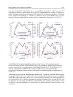
JAMSTEC has also carried out propagation measurements in seawater from a quay. The
propagation characteristics in the ELF roughly agreed with the theoretical characteristics.
The curve according to the HF measurement data as shown in figure 7 is similar to the one
that Al-Shamma’a obtained. This means that someone should make a careful investigation
at HF.
Fig. 7. Propagation characteristics of electromagnetic waves in seawater in the ELF band
(left) and the HF band (right).
JAMSTEC has been developing a new communication tool that uses electromagnetic waves.
This method is used for mutual communication between vehicles at up to 50 m distance. A
prototype transmitter, a receiver, and antennas were made. An NTSC camera for
underwater use was connected to the transmitter. The transmitter encodes and modulates
the image data and then supplies power of 17 Watts to a multi-turn coil antenna. A high
sensitivity search coil antenna receives the modulated data. The receiver demodulates,
decodes, and outputs the image in QVGA format. In the tank test, QVGA images were
transmitted to the receiver set 30 m away from the transmitter.
e. Satellite Communication system
Most satellite communications from the ocean use an earth orbiter satellite, for example
Argos satellites and Iridium satellites, rather than a geostationary satellite because the latter
needs a large sized antenna such as a parabolic antenna. However, a geostationary satellite
can provide full real-time communication and a large coverage area. The Eighth
Underwater Vehicles
566
Engineering Test Satellite, ETS-VIII has as its main purpose, dealing with the increasing
demand for digital communications, such as mobile phones and other mobile devices. The
satellite (weight of 3 tons and diameter of 40 m) has two Large Deployable Antenna
Reflectors (LDARs). Table 2 lists specifications of the ETS-VIII.
Fig. 8. Picture of ELF wave transceiver tested in tap water and a received image.
Figure 9 shows the concept of this project. Devices or facilities on the ocean are able to
communicate with land stations via a satellite with a large capacity wireless network. This
enables us to remotely control these devices or facilities, resulting in effective research in
marine-earth science. By using the ETS-VIII, remote control of an underwater vehicle from a
land station at JAMSTEC as shown in Figure 9 will be possible. For this purpose
development of a satellite communication system with help from the Japan Aerospace
Exploration Agency and National Institute of Information and Communications Technology
was started since 2003.
Items Spec. Unit Remarks
Downlink freq 2500.5-2503.0 MHz
Up link freq 2655.5-2658.0 MHz
Satellite EIRP 61.8-63.8 dBW
Satellite G/T 12-14 dB/K
Satellite Antenna Gain 41 dBi
Communication rate 64 - 384 Kbps internal ant
Table 2. The specifications of ETS-8.
A custom antenna is needed for underwater vehicles because there is no commercial
pressure-tight or water-resistant small antenna. A left-handed circularly polarized; double
resonance antenna is matched to the ETS-VIII. Antenna minimum gain is 6.3 dBi. A four-
element patch antenna, with a gain of about 14 dBi, and a single element patch antenna with
phase difference feeding lines were made. The gain of the single element planar antenna is
only 7 dBi. By decreasing the communication rate by 64 kbps, which gains 7 dB on power
per bit compared with 384 kbps, antenna margin is kept.
The ocean-based system should be equipped with a satellite tracking system to lock on to
the satellite, because of the vehicle oscillation. The tracker must also be water-resistant. For
these reasons, a tracking system has developed using data on network design and the
oscillating characteristics of the Urashima vehicle. Oscillation of the vehicle was measured
with the high accuracy inertial navigation system installed in Urashima in a sea trial. An
oscillation angle of 7 degrees and period of 0.15 Hz were estimated. We set the design target
to pitching and rolling angles of less than 20 degrees and maximum frequency of 0.5 Hz,
The tracking system consists of an attitude sensor and an attitude controller. To obtain the
direction of the satellite, an inertial navigation system and a GPS are used as attitude
sensors. The attitude controller has a three axis stepping motor driver. The system is
currently undergoing tests with the first sea trial in November 2008.
Fundamentals of Underwater Vehicle Hardware and Their Applications
567
Fig. 9. (left) An image of satellite communications with an underwater vehicle. (right)
Photograph of the attitude controller with the 4-element planar antenna.
2.3 Modern power sources
Power sources are extremely important in underwater vehicle development, in particular for
AUVs, UROVs and HROVs. Power source capacity limits the cruising range and mission
style of underwater vehicles. Two main evaluation factors for power sources are the specific
energy, energy per unit mass: Wh/kg, and the energy density, energy per unit volume:
Wh/L. In vehicle design, not only the energy of the power source is considered, but also the
maximum output power. In this section, modern power sources for intelligent underwater
vehicles, secondary batteries and fuel cells in particular are described because these are
rechargeable and are able to be run in a closed system in the underwater environment.
a. Batteries
A number of kinds of secondary battery, lead-acid, silver-zinc, nickel-MH, lithium-ion and
lithium-polymer batteries are utilized in AUV design. Lithium-ion and lithium–polymer
batteries have the advantages of easy handling, higher energy density and longer cycle life
as shown in Table 1. Davies and Moore (Davies 2007) have proposed the ratio of specific
energy and energy density, D as an index for helping power source design.
D (kg/L) = energy density / specific energy (5)
If D is smaller than the density of seawater, approximately 1.03 kg/L, a battery system has
positive buoyancy. Calculating the D of various batteries from table 1, it can be seen that
lithium type batteries have a smaller density than other types. We thus focus on lithium-ion
batteries and lithium-polymer batteries because they have good prospects for future use and
development (Armand 2008). Both batteries use lithium metallic oxide in the cathode and
carbon material in the anode. Lithium-ion batteries use lithium ions in an electrolyte inside
the battery and these transfer between the cathode and the anode during charge or
discharge. In contrast lithium–polymer batteries use a solid polymer composite. The
advantages of Li-polymer over the lithium-ion design include lower cost of manufacturing
and being more robust to physical damage.
Underwater Vehicles
568
Battery Type Specific energy, Wh/kg Energy density, Wh/L Cycle life
Lead-acid 20-30 60-80 700
Silver-zinc 100-120 180-200 100
Nickel-MH 50-70 100-150 1500
Lithium-ion 90-150 150-200 600-1000
Lithium-polymer 130-190 170-240 300-3000
Table 3. Performance of batteries (ref. Abu Sharkh 2003)
Lithium type secondary batteries have been used in a number of AUVs including
Autosub6000 (McPhail 2007), ABE (Bradley 2000), Nereus (Bowen 2004), MMT3000 (Gornak
2006), and Urashima (Aoki 2001). REMUS, which is a mass-produced compact AUV
developed at WHOI and is now commercially available only through Hydroid, Inc., also
uses lithium ion batteries. Autosub6000, 5.5 m long and 2000 kg in weight, runs over 1000
km at 1 m/s and is powered by 12 pressure balanced Lithium-polymer battery packs
including Kokam cells. Each pack stores energy of 18 MJ within 405 battery cells. The
Urashima vehicle, designed by JAMSTEC, is powered by two pressure balanced lithium-ion
battery packs: a main battery pack of 15.6kWh of energy and a 3.6 kW sub battery pack. It
has travelled over 120 km and the energy density of its batteries is about 180 Wh/L.
JAMSTEC has investigated lithium-ion battery performance by changing the cathode
material and battery shape. They have now obtained a sheet type lithium-ion battery with
an energy density of over 210 Wh/L. A pressure resistance test using an oil-filled pressure
balance case was done up to 11000 m in depth.
Utilization of lithium-based batteries will continue for a considerable period of time in the
future because most small AUV designers will choose higher energy density batteries and a
vehicle mounting a generator requires a battery for start-up. The nanotechnology revolution
will help increase the performance of lithium ion batteries in terms of capacity, power, cost,
and materials sustainability (Armand 2008) in the near future. Lithium-oxygen batteries,
which can have a capacity of 1200 mAh/g according to the reaction 2Li + O2 -> Li2O2, have
greater potential compared with lithium-ion batteries of about 150 mAh/g, theoretically.
There are now prominent failures in this type of battery but Armand expects that much
more work may break through the issues after 2050. If this battery becomes of practical use,
the cruising range of every AUV will see an eightfold increase from that of present AUVs.
b. Fuel Cells and Semi-Fuel Cells
A semi fuel cell is a generator but its usability is rather like a battery because it requires a
reactant, hydrogen peroxide, besides an exchange of the anode, due to corrosion of the
aluminium cathode in the electrical generation process, and the electrolyte.
Aluminium/hydrogen peroxide energy semi-fuel cells can theoretically generate an energy
density of 3418Wh/kg and practically one of about 400 Wh/kg. This corresponds to 3 times
that of a lithium-ion system. This type of semi-fuel cell contains only liquid and solid
materials, independently running under the ambient pressure. A vehicle designer is thus
able to design a pressure balanced battery system with a semi-fuel cell. A semi-fuel cell
would be suitable for mid size underwater vehicles because the size of a pressure-hull-less
semi- fuel cell is not so large (Adams 2002). The Hugin 3000 autonomous underwater
vehicle, 5 m long and 1400 kg in weight, uses a semi fuel cell as the main power source
(Hasvold 2002). This semi-fuel cell generates energy of 45 kWh for 50 hours.
Fundamentals of Underwater Vehicle Hardware and Their Applications
569
Many types of fuel cell system have been developed around the world. Proton exchange
membrane fuel cells (PEMFC) are the most suitable for underwater applications such as for
autonomous underwater vehicles. Its operation temperature are around 70 degrees Celsius
and its reactive product is only pure water. Underwater, a typical PEMFC system for land
applications, such as found in automobiles, cannot be used because intake air does not exist
underwater and the water reaction product is not easily drained into the high pressure
external environment. The underwater vehicle Urashima is equipped with a closed-cycle
PEFC system that consists of a fuel cell generator, high pressure oxygen tank, and a metal
hydride tank. Its generating system must be perfectly closed so that there is no emissions
underwater. The energy density of the fuel cell generator itself is high, although for the
whole fuel cell system has a lower value due to weight gain from hydrogen, oxygen, and
reactant water tanks, auxiliary components, and control electronics. Decreasing the size and
weight of these devices is needed for underwater applications of fuel cell technology.
JAMSTEC has developed underwater vehicles for surveys in the vast underwater
environment. The vehicles are utilized for sea floor observations, ocean environmental
research, energy source exploration, and research on marine organisms and micro-
organisms. One of the important underwater vehicles is an AUV with a large capacity
energy source, a highly accurate positioning system, and a smart control system for
autonomous cruising. In 2005, JAMSTEC made a world record of cruising distance of 317
km by the autonomous underwater vehicle Urashima, powered by a closed-cycle PEFC
system. They aim to develop an underwater platform that can survey across entire oceans
for scientific research into global climate change, ocean-trench earthquakes, marine
microorganisms and multicellular organisms. In 2007, they started research and
development on a second generation long-range cruising AUV (LCAUV) to cruise over 3000
km. The development of an improved power source for the vehicle is important to realize
this goal. A fuel cell system has to be the best choice for a power source aimed at long-range
cruising with a limited payload.
The PEFC system for the LCAUV must satisfy the following requirements; 1) high efficiency
(over 60 %), 2) fuel of pure hydrogen and oxygen and downsizing of the storage system, 3)
leakless stacks, 4) perfectly closed system, 5) over 600 hours continuous running time (need
high reliability and durability), and 6) small system. Table 1 shows the power system
specifications required of successive LCAUVs.
Term Platform Endurance Ran
g
ePower ca
p
acit
y
1998 -
p
resent Urashima 60h 300 km 4 kW
(
Max
)
180 kWh
2007 - 2015 2nd LCAUV 600h 3
,
000 km 10 kW
(
Max
)
5000 kWh
2016 or later 3rd LCAUV ? 10
,
000 km ? ?
Table 4. Power system specifications
Urashima, the first prototype of a fuel cell-driven underwater vehicle built by Mitsubishi
Heavy Industry Ltd., has the following specifications: length; 10 m, weight; 10 tons,
maximum depth rating; 3500 m, maximum cruising speed; 3.2 knots, and endurance; 60
hours. Fuel cells for underwater vehicles should run on pure-hydrogen and pure-oxygen
since no air exists underwater. The water byproduct produced in the fuel cell should be
stored in the vehicle body to keep its buoyancy constant. If the reactant water is pumped
into the external environment, the vehicle consumes much more energy and the vehicle
loses weight and will start to float. We have thus developed a completely closed fuel cell
Underwater Vehicles
570
system, which confines energy resources and reactant water to the system, namely the
closed-cycle PEFC system as shown in Figure 10. This FC system consists of two stacks,
recirculation blowers, humidifiers, a heat exchanger and a reactant water storage tank,
generating power of 4 kW. All devices are installed into a titanium pressure vessel. The
coolant water from the FC stack is reused to humidify the hydrogen gas. A metal hydride
(MH) vessel and a high-pressure oxygen tank are included. The heat generated in the FC
stack is applied to heating the MH to extract hydrogen from the MH and the excess heat is
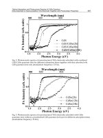
radiated into seawater. Figure 11 shows a typical I-V plot of the PEFC system obtained in
the 317 km sea trial. The maximum FC system efficiency was about 54 % at typical cruising
speed.
Fig. 10. System configuration of the closed-cycle PEFC for Urashima.
Fig. 11. I-V plotting of the closed-cycle PEFC during a 317 km.
The target cruising range of the 2nd LCAUV has increased tenfold from that of the Urashima.
JAMSTEC has set target specifications for the fuel cell system, with system efficiency of over
60 % and downsizing of the pressure vessel and tanks as shown in Table 2. They made and
tested a single cell which consists of a solid polymer electrolyte membrane, carbon black,
platinum-alloy, carbon paper, and metallic separators. The test was done under the
following conditions: cell temperature of 60 degrees Celsius, process pressure of 300 kPaA,
and gas utility factor of 50 %. Figure 12 shows an I-V plot of the new cell compared with the
Urashima system. In the figure the circle and the square show that of Urashima and that of
the new cell, respectively. They have a single cell efficiency of 60 % at a higher heating value
Fundamentals of Underwater Vehicle Hardware and Their Applications
571
in the target current point. Now JAMSTEC has designed a blower- and humidifier-less system
using the new cells.
Platform Efficiency Volume ratio
Urashima 54 % 1
2nd LCAUV 60 % 1/2 or less
Table 5. Required PEFC specifications for underwater vehicle
0.6
0.7
0.8
0.9
1.0
1.1
0 5 10 15 20
C u rre n t[A]
Cell V o lta g e [V]
URASHIMA
HGC- 1
Fig. 12. I-V curve of new cell
3. Data processing
3.1 Control hardware: internal communication bus and distributed CPU system
In control hardware robustness, reliability, high speed, synchronization are important. A
distributed CPU system reduces concentration of processing load on a single CPU and
allows system redundancy. A distributed CPU system can be composed of printed circuit
boards with an embedded CPU chip and an internal bus. In the distributed real-time system,
it is important which internal bus is the best for the system considered. Some researchers
(Weidong 2006, Blandin 1998, Yoshida 2004) proposed the the Controller Area Network
(CAN) bus which was originally developed in the 1980's by R.BOSCH GmbH as an internal
bus for AUVs. The CAN bus is based on the broadcast communication mechanism. Every
message has a message identifier, which is unique within the whole network since it defines
content and the priority of the message. The CAN bus also has the mechanism of bit and
frame synchronization. The maximum data transmission rate of CAN is 10 MHz.
3.2 Image sensing and recognition
a. Midwater Organism Tracker
PICASSO will semi-automatically track animals in midwater. In order to detect and track an
animal the vehicle has to incorporate animal image recognition and then automatically
move so as not to lose the animal that has been recognized. JAMSTEC has developed a
prototype system for an animal tracker using the MROV vehicle. To simplify the prototype
system, only the pan-tilt system of the camera rather than the entire vehicle itself was
Underwater Vehicles
572
controlled by the tracking program. Color deference in HLS (Hue, Saturation, Luminance)
color space was basically used for detection. Identification of a target is initially done by
clicking on the target on the display. RGB values in the 9 x 9 pixels around the pixel clicked
are converted to the HLS color space. A center of gravity for pixels with the near-HLS value
obtained is then calculated. When the distance between the center of gravity and the center
of the image obtained by the camera exceeds a preset limit of the pan-tilt, the program
controls the camera to center the animal in the middle of the observation space. The
program also has a displacement prediction function to predict movements of animals.
A detection and tracking test was carried out in the large fish tank (6.5 m in depth, 144 m
2
area of base) at the Enoshima Aquarium. A scene taken during the test is shown in Figure
13. The prototype system was able to detect and track a small fish (red circle in the figure)
for 30 seconds in this test. However, in most cases the duration of capturing the target was
only a few seconds because there were many fish in the tank and the background-target
contrast was low compared to in the midwater zone of the ocean. For more accurate
detection, they will collaborate on an image recognition method with MBARI (Walther
2004). This method simulates human vision functions and has a high target recognition
probability. JAMSTEC will also investigate a program to track animals by linking this
output with thruster control.
Fig. 13. A tracking test using the MROV in the Enoshima Aquarium. The cross shows the
tracking point.
4. Present intelligent underwater vehicles
In this section, vehicles, equipped with state-of-the-art devices, that were developed at the
institute for which the author works are the mainfocus.
4.1 Plankton survey vehicles
Research on planktonic organisms is important because they are the link between
greenhouse gases being absorbed by the ocean and the final burial of these gases as solid
organic carbon in deep sea sediments. Planktonic organisms also occur at very high point
biodiversities and insights into how so many species can co-exist in a seemingly
homogeneous environment should help shed light on aspects of biodiversity that need to be
grasped for protection of biodiversity hotspots and to understand evolution.
Fundamentals of Underwater Vehicle Hardware and Their Applications
573
Several trials with ROVs and manned submersibles (Wiebe & Benfield, 2003) have been
carried out to investigate the distributions of macro- and micro-plankton versus
environmental parameters. In this way, one is only able to gain information of a point
nature and it is not possible to determine large-scale distributional patterns with limited
ship-time. Both winch-controlled towed systems (MOCNESS net, BIONESS net,
BIOMAPER-II system) have been equipped with a combination of imaging, acoustic and
environmental parameter sensors. However, the maximum operation depth for the
BIOMAPER-II and SeaSoar were only 300 m and none of these systems had imaging
systems of high enough resolution to identify and quantify plankton at the species level
(Wiebe & Benfield, 2003).
Since 2005, JAMSTEC has been developing a multiple-platform autonomous survey system
able to quantitatively characterize the midwater environment, including fragile components
such as large particulates and gelatinous plankton. This system could be deployable from
small to medium sized boats and ships.
Since 2006, we have developed the first small vehicle named PICASSO-1 Plankton
Investigatory Collaborating Autonomous Survey System Operon-1. Fig. 14 shows a snap
shot of PICASSO-1 during a sea trial. PICASSO-1 is small and light (2.4 m long, 200 kg in
weight) and the color of the hull is mostly red because deep sea organisms cannot see light
or reflections in the red spectrum as a rule. The vehicle system consists of an on-board
topside module and a vehicle, and these are connected via a thin optical fiber cable. One
remotely controls the vehicle from the topside module. PICASSO-1 is composed of the
following major parts: an FRP fairing cover, a body frame, buoyancy materials, controllers,
communication systems, three 100 W thrusters, one tilt actuator, lights, devices for
navigation and observation, oil-filled lithium ion battery, and an optical fiber spooler. The
vehicle has one vertical tail fin and two fins for stability. Table 6 shows the PICASSO-1
specifications.
Item Specification Remarks
Dimension 2.1 m x 0.8 m x 0.8 m without VPR
Weight 200 kg in air
Depth rating 1,000 m
Cruising speed 2 kt
Endurance 6 hours
Operation mode UROV
Propulsion 2 horizontal 100 Watt thrusters with tilt system,
1 vertical 100 Watt thruster
Communications
instrumentation
2 G bps optical communication device ,
Radio LAN, ARGOS transmitter, acoustic and
magnetic transceiver*.
Navigation
instrumentation
MEMS gyro, Doppler velocity log, depth meter,
SSBL, compass
Experiment
payload
CTD, TDO, Fluorometer-Turbidity sensor, 4 x
NTSC cameras, 3 x 35 Watt HID lamps, Visual
Plankton Recorder*, High definition TV camera*,
Digital still camera*, 400 watt HID lamp*.
* pick only
one device
Table 6. Specifications of PICASSO-1