báo cáo khoa học: "Direct microcontact printing of oligonucleotides for biochip applications" docx
Bạn đang xem bản rút gọn của tài liệu. Xem và tải ngay bản đầy đủ của tài liệu tại đây (859.76 KB, 12 trang )
BioMed Central
Page 1 of 12
(page number not for citation purposes)
Journal of Nanobiotechnology
Open Access
Research
Direct microcontact printing of oligonucleotides for biochip
applications
C Thibault
†1
, V Le Berre
†2,3
, S Casimirius
1
, E Trévisiol
2,3
, J François*
2,3
and
CVieu*
1
Address:
1
LAAS-CNRS, 7, avenue du Colonel Roche 31077 TOULOUSE Cedex 4,
2
Biochips Platform Genopole Toulouse, UMR-CNRS 5504 &
INRA 792, 135, avenue de Rangueil, 31077 TOULOUSE Cedex 4 and
3
Laboratoire de Biotechnologie & Bioprocédés, UMR-CNRS 5504 & INRA
792, 135, avenue de Rangueil, 31077 TOULOUSE Cedex 4
Email: C Thibault - ; V Le Berre - ; S Casimirius - ; E Trévisiol - trevisiol@insa-
toulouse.fr; J François* - ; C Vieu* -
* Corresponding authors †Equal contributors
microcontact printingelastomeric stampDNA immobilisationbiochipsdetection of mutations
Abstract
Background: A critical step in the fabrication of biochips is the controlled placement of probes
molecules on solid surfaces. This is currently performed by sequential deposition of probes on a
target surface with split or solid pins. In this article, we present a cost-effective procedure namely
microcontact printing using stamps, for a parallel deposition of probes applicable for manufacturing
biochips.
Results: Contrary to a previous work, we showed that the stamps tailored with an elastomeric
poly(dimethylsiloxane) material did not require any surface modification to be able to adsorb
oligonucleotides or PCR products. The adsorbed DNA molecules are subsequently printed
efficiently on a target surface with high sub-micron resolution. Secondly, we showed that successive
stamping is characterized by an exponential decay of the amount of transferred DNA molecules to
the surface up the 4
th
print, then followed by a second regime of transfer that was dependent on
the contact time and which resulted in reduced quality of the features. Thus, while consecutive
stamping was possible, this procedure turned out to be less reproducible and more time consuming
than simply re-inking the stamps between each print. Thirdly, we showed that the hybridization
signals on arrays made by microcontact printing were 5 to 10-times higher than those made by
conventional spotting methods. Finally, we demonstrated the validity of this microcontact printing
method in manufacturing oligonucleotides arrays for mutations recognition in a yeast gene.
Conclusion: The microcontact printing can be considered as a new potential technology platform
to pattern DNA microarrays that may have significant advantages over the conventional spotting
technologies as it is easy to implement, it uses low cost material to make the stamp, and the arrays
made by this technology are 10-times more sensitive in term of hybridization signals than those
manufactured by conventional spotting technology.
Published: 01 July 2005
Journal of Nanobiotechnology 2005, 3:7 doi:10.1186/1477-3155-3-7
Received: 11 April 2005
Accepted: 01 July 2005
This article is available from: />© 2005 Thibault et al; licensee BioMed Central Ltd.
This is an Open Access article distributed under the terms of the Creative Commons Attribution License ( />),
which permits unrestricted use, distribution, and reproduction in any medium, provided the original work is properly cited.
Journal of Nanobiotechnology 2005, 3:7 />Page 2 of 12
(page number not for citation purposes)
Background
DNA microarrays have rapidly evolved to become one of
the essential tools to investigate expression or mutation of
thousands of genes simultaneously. Two main technology
platforms for manufacturing DNA chips have emerged.
The first platform uses the immobilization of prefabri-
cated DNA or oligonucleotides by spotting on functional-
ized glass slides using metal pins as originally developed
by Brown and collaborators (see n
ford.edu/pbrown/index.html), or by a non-contact
method using piezoelectric liquid handling [1]. The sec-
ond platform rests on the direct in-situ synthesis of oligo-
nucleotides (between 20 to 70 mers in general) on glass
slides or silicon surfaces, as developed by Affymetrix or
Agilent [2]. A typical characteristic of these techniques is
the sequential nature of the process. One molecule is
deposited after another or one base is added to the previ-
ous one, with the consequence that each array is made as
an original with a reduced throughput, although Affyme-
trix microarrays manufacturing involves combinatorial
processes that allow multiple microarrays (around 96) to
be synthesized in parallel in matters of hours. Neverthe-
less, these technology platforms needs sophisticated
equipment, leading to high density arrays that can be too
expensive for production and utilization of simple-cus-
tomized-DNA arrays.
There is a need for alternative patterning methods that
must be very simple, reproducible, cost-effective, and
eventually transferable to any laboratories for their own
problematic. The microcontact printing (µCP) could ful-
fill this requirement as it is a printing technology that uses
cheap elastomeric stamps made usually of polydimethyl-
siloxane (PDMS) and which exhibits relief patterns at the
micron and nanoscale [3]. These stamps let to parallel
deposition of molecules on a target surface, in the same
manner as the printing of a page of book instead of a letter
being written individually to compose the page. Previous
works demonstrated that proteins can be deposited on a
substrate surface by microcontact printing (µCP) [4,5].
More recently, Lange et al. [6] showed that µCP technique
can be used to deposit DNA molecules with a PDMS sur-
face of the stamp chemically modified to enable the DNA
molecules to stick on the stamp. This functionalization
step strongly restricted the speed of this technology, as it
takes several hours from the conversion of the CH
3
termi-
nated surface of the PDMS into an aminated surface to
complete inking of the stamps prior to printing the target
surface.
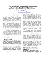
In this paper, we demonstrate that µCP can be used to fab-
ricate DNA biochips directly without any surface modifi-
cation of the stamps. We show that inking and contact
times of less than 30 seconds give high quality and high
resolution arrays by µCP. According to our new variant of
the process, the stamp is simply inked with the molecules
of interest, dried under a nitrogen stream and then printed
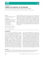
manually onto the substrate surface (see Fig. 1). It is fore-
seen that this technology platform will be highly compet-
itive for high throughput analysis of gene expression and
mutation detection analyses. Moreover, this technique
can be easily implemented for sub-micron patterns as
demonstrated previously [6] and in this work.
Results and Discussion
The two main steps of µCP are the adsorption of the bio-
molecules on the stamp (inking process) and the transfer
from the stamp to a target surface (contact printing). It is
important that the retention of molecules on the stamp
surface does not prevent their subsequent transfer to the
slide, and that the inking and the contact time were as
short as possible for optimizing the high throughput of
the technique. In a recent work [6], this compromise was
obtained by a specific chemical treatment of the elasto-
meric poly(dimethylsiloxane) material (PDMS) of the
stamp after molding. In contrast to this report, we found
that untreated PDMS stamp that has a strong hydrophobic
surface after curing, easily adsorbs a sufficient amount of
DNA molecules within few seconds while allowing their
subsequent deposition by contact on microscope glass
slides or silicon. The printing process works for untreated
glass or silicon surfaces, but real bioassays were carried
out on treated glass surfaces enabling strong binding of
the probe molecules. During the contact, the purpose is to
transfer efficiently and as quick as possible the molecules
from the stamp surface to the slide without affecting the
size of the patterns. A specific chemistry on the surface of
the slide is also important for the attachment of the
probes after taking away the stamp from the surface. We
also verified that stamps could be reused several times
after cleaning in deionized water. The experiments
detailed below aim at investigating the influence of sev-
eral parameters including the surface chemistry of the
slide, the inking and the contact time of the stamp, and to
demonstrate the potentiality of this technique for actual
biochips.
Surface chemistry and high uniformity of DNA printing on
target surfaces
Experiments reported in this paper were carried out using
two different type of glass slides that differed by their sur-
face functionalization: positively charged amine glass
slides (Ultra Gap, Dow corning) and dendrislides, which
are glass slides that have been functionalized with nano-
metric spherical dendrimeric particles bearing aldehydes
reactive group at the periphery for covalent attachment of
the 5'-NH
2
probes [7,8]. These two types of functionalized
slides were printed for 15 sec with a stamp that has been
incubated for 30 sec with a 10 µM solution of 35-mers 5'-
NH
2
probe in Na-phosphate buffer at pH 9.0.
Journal of Nanobiotechnology 2005, 3:7 />Page 3 of 12
(page number not for citation purposes)
Hybridisation was achieved using a 15-mer 5'Cy5 target
complementary to the 35-mer 5'-NH
2
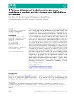
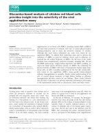
probe. As shown on
Fig. 2, the micronic features of the stamp (squares, disks,
gears, crosses, spirals, ) were clearly noticeable on both
types of glass slides. However, we observed systematically
a greater signal to noise ratio, a better uniformity and edge
definition of the spots with dendrislides (Fig. 2B) than
with electrostatic slides (Figure 3A). This result is consist-
ent with our previous report that the functionalization of
surface with dendrimers reduces the non specific adsorp-
tion of fluorescent material [8]. In addition, the "donut"
formation of spots frequently obtained after deposition of
DNA molecules by contact spotting was no longer
observed since the µCP is a "dry" deposition technique.
This enables a better treatment of the fluorescence images
for quantitative analysis. The upper part of Fig. 2C shows
few lines on the array that exhibit a pitch of 4 µm which
could only be seen as very small red spots because the flu-
orescent scanner cannot resolve the features. A magnifica-
tion on conventional features (i.e. squares and disks) is
shown in Fig. 2D. On this image, the contour of the pat-
terns was mainly blurred by the pixel size of the scanner.
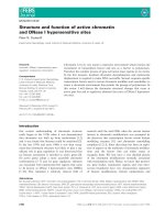
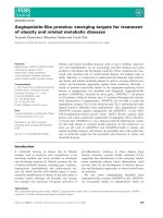
In order to allow Atomic Force Microscopy (AFM) charac-
terization, submicronic features were printed on silicon
surface instead of glass slides to minimize the surface
roughness. These patterns consisted in a periodic array of
500 nm wide lines at a pitch of 1 µm. As shown in Fig. 3,
the 500 nm wide lines are clearly visible and the printed
oligonucleotides appear as small aggregates that could be
distinguished from the smooth surface of the silicon sub-
strate. It is worth noticing that in this case the surface of
the sample could not be rinsed after printing, because the
untreated silicon surface does not provide strong adhe-
sion of DNA molecules. Edge roughness and small aggre-
gates visible on the image can be possibly attributed to
residues coming from the buffer solution.
Inking time
In our first trial, the molded PDMS stamps were incubated
at room temperature in the oligonucleotides solution for
different times ranging from 30 sec to 1 hr, and then
printed on a dendrislide after drying. Under these condi-
tions, a very high and saturating fluorescent intensity was
obtained independently of the inking time, likely because
the amount of transferred fluorescent DNA molecules to
the surface was already very high at the shortest inking
time tested. It was even possible to observe deleterious
effects for excessive inking times due to excess fluorescent
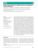
Principe of microcontact printing of DNA moleculesFigure 1
Principe of microcontact printing of DNA molecules. (1) Inking of the stamp with the oligonucleotide solution, a 1 cm
2
stamp is loaded with a 2 to 20 µl droplet of solution for a given time (2) drying of the stamp under Nitrogen stream, (3) manual
contact between the inked PDMS stamp and the glass slide, (4) probe molecules are transferred on the slide along patterns
that correspond to the relief structures of the PDMS stamp.
Journal of Nanobiotechnology 2005, 3:7 />Page 4 of 12
(page number not for citation purposes)
Comparison between two types of slidesFigure 2
Comparison between two types of slides. Fluorescence images of printed micronic patterns. Stamp was incubated with a
35-mers probe oligonucleotide for 30 sec, then put in contact for 15 sec with two types of microscope glass slides. A, electro-
static slide (ultra Gap, corning), B, dendrislide (home made slide). Slides were then incubated with a 15-mer 5'-Cy5 labeled oli-
gonucleotide. C and D are a zoom area of B.
Journal of Nanobiotechnology 2005, 3:7 />Page 5 of 12
(page number not for citation purposes)
material deposited at the periphery of the stamp (data not
shown). These results indicated that the PDMS surface
was saturated with DNA molecules in less than 30 sec of
inking. We therefore reduced the inking time to a period
that is easily compatible with a handling procedure of the
stamps, i.e. 15 sec.
To explain the excellent performance of this technique to
print DNA probes, we suggest that a hydrophobic interac-
tion takes place between the PDMS surface of the stamp
and single strand DNA molecules, since the PDMS surface
is highly hydrophobic, and the DNA strand can also
exhibit hydrophobic properties through its bases content,
even though it is an hydrophilic molecule. Moreover,
hydrophobic interactions are 10 to 100 times stronger and
have a longer range of action than the Van der Waals inter-
actions [9,10]. On the other hand, a fast and efficient
transfer of the DNA probes from the stamp to the slide
required that the interacting forces between the oligonu-
cleotides and the PDMS surface must be weaker than
those occurring between the oligonucleotides and the sur-
face of the slide. This was verified in our experiments for
both positively charged and hydrophobic dendrimeric
activated surface slides. As a consequence, preserving the
hydrophobicity of the PDMS stamp is clearly a key point
in order to reduce the inking times for DNA printing and
to favor the subsequent transfer of the molecules to either
a positive charged or a hydrophobic surface. This is the
main difference between our work and that of Lange et al
[6]. In this latter work, the adsorption of DNA probes on
the stamp was mainly based on electrostatic interactions
with the consequence of long inking period (45 min.). In
addition, as the surface treatment of PDMS is known to be
unstable on air, our process, which does not involve any
surface modification after molding, should be more
reproducible and should allow the reusability of the
stamp (see below). It is worth to note that similar results
were obtained using long single DNA molecules or dou-
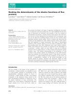
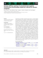
ble stranded PCR fragments. However, as can be seen in
Fig. 4, the signal intensity was significantly lower with
stamped PCR products than with oligonucleotides. This
observation was actually not specific to this technique
since the same results were observed using conventional
fabrication of arrays by mechanical spotting (V. Le Berre,
unpublished data).
Contact time and successive prints
To identify the transfer mechanisms of the molecules
from the stamp surface to the slide, we investigated the
influence of the contact time and the evolution of fluores-
cent signals after successive prints with the same stamp
loaded with a fluorescent 35-mer 5'-labelled Cy5-oligonu-
cleotide-3'NH
2
(5'Cy5-TTAGCGCATTTTGGCATATTT-
GGGCGGACAACTT-NH
2
-3'). On the same slide,
Example of DNA printing at the submicronic scaleFigure 3
Example of DNA printing at the submicronic scale. AFM image (taping mode) of 30-mers 5'-GCATGCTTAGTT-
GCTATTATCAAAATA-3', corresponding to BCK2 yeast gene printed on an untreated silicon surface. The pitch of the peri-
odic array of lines is 1 µm. Note that the chemical surface states of the silicon was not really controlled: rough native oxide.
Journal of Nanobiotechnology 2005, 3:7 />Page 6 of 12
(page number not for citation purposes)
consecutive stamping steps were performed with a contact
time of 15 sec, 1 min or 2 min, which took in total 2 to 20
min to pattern a dendrislide with 10 successive prints. To
evaluate the change in fluorescence intensity along the
successive print, the total intensity subtracted from the
local background of specific features on the patterned
slide were integrated and compared to the total intensity
from the first print which was set arbitrarily at 100%. As
shown on Fig. 5, this change followed an exponential
decay up to the 4
th
stamping, and surprisingly, this decay
was dependent of the contact time. The following
equation
-dN/dn = kN
where N
is the number of molecules deposited on the
slide at print number n
, could be used to determine the
characteristic of k
, a kind of sticking coefficient of the mol-
ecules on the surface. The extracted values for k turned out
to be dependent upon the contact time, with k increasing
as the contact time decreased (k = 1.36 for t = 15 s, k = 0.67
for t = 1 min, k = 0.57 for t = 2 min). This result indicated
that longer the contact time, slower was the depletion of
the stamp in biomolecules. This behavior is suggestive of
a slow diffusion of the molecules retained inside the cav-
ity of the PDMS stamp to its relief structures that are in
contact with the slides, as depicted in Fig. 6. It is therefore
expected to observe a slower decrease of the fluorescence
intensity for increasing contact times because there is
more time for the biomolecules to migrate to the surface.
In addition, we calculated that the k coefficient roughly
changes with the inverse of the square root of the contact
time, which is consistent with a diffusion limited deposi-
tion mechanism. Accordingly, the exponential decay of
the fluorescence signal was no longer valid after 4 succes-
sive printing steps (Fig. 6). For n > 4, the number of
molecules initially adsorbed on the relief structures of the
PDMS stamp has been largely depleted in previous prints.
However, a low fluorescence intensity that decrease very
slowly from the 5
th
to the 7
th
print was still measured. This
suggested a slow diffusion of molecules from the edges of
the pattern to the slides during the contact. In that case,
the number of printed molecules should be higher at the
periphery of the features than in the center. The fluores-
cence images of the 5
th
to the 7
th
print for a contact time of
2 min nicely confirmed this assumption (Fig. 7). Essen-
tially the rims of the specific features were recognizable
likely because the remaining molecules had enough time
to migrate from the edges of the relief printing of the
stamp to the glass surface during the contact time. Thus, at
shorter contact times, the fluorescence images were even
worse (not shown), and hence the intensity values were
lower (see Fig. 5).
As a conclusion of this section, we clearly identified some
problems related to diffusion of biomolecules during
stamping that may hamper the production of high quality
arrays by successive stamping without re-inking. On the
other hand, taking into account that the loading of the
stamp is very fast and that high quality deposition by µCP
of DNA molecules takes less than 15 sec to give optimal
fluorescence signals, it appears more favorable to re-ink
the stamp during 15 – 30 sec after each print, which is
eventually faster than consecutive print.
Comparison between oligonucleotides and PCR fragmentsFigure 4
Comparison between oligonucleotides and PCR frag-
ments. Fluorescent images of typical micrometric printed
features. Stamp was incubated for 30 sec with a 500 bp PCR
fragment (dsDNA) of the yeast HSP12 gene (A) or with a 20-
mer oligonucleotide of the same yeast gene (B), then set in
contact manually for 15 sec with a dendrislide. Hybridisation
was carried out with HSP12 complementary Cy5-labelled oli-
gonucleotide. Values of fluorescence intensity were meas-
ured at 635 nm with the GenePix 4000B from axon at 600
PMT. Mean intensity at 635 of 12 features on two experi-
ments – Background was 2120 for A and 4119 for B.
Journal of Nanobiotechnology 2005, 3:7 />Page 7 of 12
(page number not for citation purposes)
Comparison between
µ
CP deposition and contact
deposition using metal pins
In order to compare µCP with a conventional spotting
method, we performed a dedicated experiment in which
the fluorescence intensity of DNA array was determined as
a function of the concentration of the DNA probe used to
manufacture the slides by the two techniques. To allow a
direct comparison between the two methods, spots of 60
µm diameter size made with different concentration of
20-mer oligonucleotides from HSP12 were spotted with a
commercial spotter (VersArray ChipWriter Pro, Biorad
company) on a dendrislide, and disks of the same dimen-
sion were printed by µCP under the same condition. The
arrays were then hybridized with the complementary
labeled molecules. Fig. 8 shows the evolution of the fluo-
rescence intensity in arbitrary units as a function of the
Fluorescence signal variation for successive printsFigure 5
Fluorescence signal variation for successive prints. Variation of the fluorescence intensity for successive prints and for
three different contact times (15 seconds, 1 minute and 2 minutes) between the stamp and the slide. Stamp was incubated with
a 35-mer 5'-labelled Cy5 oligonucleotide for 30 sec than put in contact with the dendrislides. The value of fluorescence inten-
sity (fluorescent – background) was measured at 635 nm with Genepix scanner under 600 PMT optical excitation. Each point
represents an average of 4 independent experiments. Fittings of the data points with an exponential linear regression (solid
lines), exhibits good agreement as attested by the reported correlation factors R.
Journal of Nanobiotechnology 2005, 3:7 />Page 8 of 12
(page number not for citation purposes)
initial concentration of the probe. From a range of 0.1 to
10 µM, the fluorescence signal was 5 to 10-fold higher
when the deposition was performed by µCP than by a
conventional spotter. This significant difference could be
explained by the fact that deposition with a dry stamp in
which the DNA molecules are delivered at the interface
between the elastomeric material and the slide surface
could offer uniform layers of densely packed molecules.
Conversely, the deposition of a liquid droplet on the slide
surface, which is let to evaporate, may give irregular layers
of dispersed molecules. Alternatively or complementary
to this explanation, it is possible to consider that the
probes printed on the surface by µCP are better organized
than by spotting, enabling a greater amount of targets
accessible to the probes. In any case, for a given signal/
noise ratio, the amount of probe molecules is significantly
lower to get the same hybridization signals using µCP as
compared to the spotting technology. This could be in the
future a reasonable advantage of this technique taking
into account the prohibitive price of DNA probe mole-
cules. Moreover, this printing procedure is versatile and
gives also excellent results with longer DNA molecules or
double stranded PCR fragments.
Mutation detection
Having demonstrated that oligonucleotides can be suc-
cessfully printed in multiple copies, yielding uniform pat-
terns, we investigated the possibility to manufacture an
array bearing short oligonucleotides of a given gene by
µCP for detecting a single mutation as it can be made with
the DNA microarray technology [11,12]. We printed 5 dif-
ferent 20-mer oligonucleotides from HSP12, encoding a
protein chaperone in yeast [13]. These probes differed
from each other by a single or a double base mutation at
positions proximal to the 5' or 3' end or in the middle of
the sequence. These oligonucleotides were then hybrid-
ized with Cy5-labelled cDNA prepared from total yeast
RNA (see method section for additional details) in the
automatic hybridization room. We compared the hybrid-
ization intensity of the target molecules on the printed
patterns with that from the perfectly matching target
sequence to the 20-mer oligonucleotide probe. We
observed that whatever the position and nature of the
mutation, the hybridization signal was considerably
reduced for mutated sequences. As expected, the position
of the mutation along the sequence of the probe molecule
strongly influenced the hybridization ratio (Fig 9). This
experiment was repeated 4 times independently and
yielded highly reproducible data with a statistical devia-
tion of <1%. Altogether, these results were very similar to
those obtained using microarrays fabricated with dendris-
lides by a conventional spotting method [7]. This indi-
cates that the quality of the arrays printed by µCP with
respect to hybridization assay is largely equivalent to
arrays produced by conventional deposition techniques.
Proposed mechanism for the diffusion of oligonucleotides during stampingFigure 6
Proposed mechanism for the diffusion of oligonucleotides during stamping. This picture shows schematically the
possible migration direction of the oligonucleotides on the stamp surface during contact. This flow could explain the preferen-
tial deposition of molecules at the rim of the patterns.
Journal of Nanobiotechnology 2005, 3:7 />Page 9 of 12
(page number not for citation purposes)
Conclusion
In this work, we demonstrated that µCP is a new potential
technology platform to pattern DNA microarrays at a rel-
atively high speed, high resolution and high reproducibil-
ity. Two additional features which may provide significant
advantages of this technology over the conventional spot-
ting technologies are: (i) the simplicity of the µCP associ-
ated with the low cost of the material employed to make
the stamp, and (ii) the arrays made by µCP technology
provide 10-times higher fluorescence intensity after
hybridization compare to those manufactured by conven-
tional spotting technology. With these advantages in
mind, our next step will be the fabrication of a dedicated
automatic X, Y, Z controlled tool for printing different
probe molecules with a high throughput. In the future,
µCP may help to simplify, accelerate and improve the fab-
rication of microarrays and increase significantly their
reliability and accessibility in i.e. clinical applications.
Comparison between first and last print with the same stampFigure 7
Comparison between first and last print with the same stamp. (A) shows the fluorescent image of the patterns trans-
ferred at the first print, and (B) shows the printing patterns after 5
th
(B1), 6
th
(B2) and 7
th
print (B3). Stamps were inked with a
15-mer 5'-labelled Cy5 oligonucleotide for 30 sec and then set in contact for 2 min with the dendrislide. The well defined fea-
tures is shown in (A) whereas only the rims of the patterns were detected after the 4
th
print (B).
Journal of Nanobiotechnology 2005, 3:7 />Page 10 of 12
(page number not for citation purposes)
Methods
Stamp fabrication
The first step of fabrication consists in generating a silicon
master. This was achieved by proximity U.V. photolithog-
raphy on a Si [100] wafer coated with positive resist (AZ
1529), and pattern transfer by deep Reactive Ion Etching
(1.4 µm deep). For submicronic patterns, Electron beam
lithography on PMMA (PolyMethylMetAcrylate) was used
instead of UV photolithography and the etch depth was
limited to 100 nm. To enable simple demoulding of this
master, an anti-adhesive treatment is carried out using
silanisation in liquid phase with OTS (octadecyltrichlo-
rosilane). The final step consists to cure the PDMS pre-
polymer solution containing a mixture (10:1 mass ratio)
of PDMS oligomers and a reticular agent from Sylgard 184
Kit (Dow Corning) on the silicon master. The PDMS was
thermally cured at 120°C for 90 min or for 12 hr at 80°C
(both methods giving similar results of stamping). A
silicon master can be reused more than 50 times and each
stamp can be used for a large number of prints (>100).
Surface chemistry of the substrate
Two kinds of microscope glass slides were used for spot-
ting and printing the probes. Using "electrostatic" glass
Comparison between µCP deposition and contact deposition using metal pinsFigure 8
Comparison between µCP deposition and contact deposition using metal pins. Evolution of the fluorescence inten-
sity in arbitrary units as a function of the concentration of the solution containing the probe molecules. 60 µm diameter spots
of 20-mer oligonucleotides from HSP12, were deposited using a commercial Spotter (VersArray ChipWriter Pro, BIO-RAD)
and then hybridized with the complementary labeled molecules. Disks and square of the same dimension were printed by µCP
and treated exactly in the same conditions.
Journal of Nanobiotechnology 2005, 3:7 />Page 11 of 12
(page number not for citation purposes)
slides that are positively charged amine glass slides (Ultra
Gap, Dow corning), the printed/spotted probes were
cross-linked onto the amine surface by UV light at 300 mJ.
With dendrislides (home made slide bearing generation 4
dendrimers, see [7], and our web site: a-
toulouse.fr), a covalent attachment of the probes on the
glass surface through aldehyde function of the dendrimers
was performed [8,9]). After spotting, the dendrislides
were allowed to dry overnight at room temperature. The
reduction of the imines function formed between probes
and dendrimer was carried out by immersion of the slides
into a solution containing NaBH
4
at 3.5 mg/ml for 3 hr at
room temperature under agitation. The DNA slides were
washed three times in water during 2 min, at room tem-
perature and then dried under a stream of nitrogen.
Stamping process
Stamps were incubated with 2–20 µl of a 10 µM oligonu-
cleotide solution made in Na-phosphate buffer 0.3 M, pH
9 for only 30 sec (unless mentioned differently), and then
blown dried under a stream of nitrogen. Then, the stamp
was printed manually onto the substrate surface and left
in place during a controlled contact time. A 35-mer 5'-
labelled Cy5-oligonucleotide-3'NH
2
(5'Cy5-TTAGCG-
CATTTTGGCATATTTGGGCGGACAACTT-NH
2
-3'), a 35-
mer 5'-amino modified (5'NH
2
-GTGATCGTTGTATC-
Mutation detectionFigure 9
Mutation detection. Comparison of the hybridization signal intensity of the target molecules on 5 different printed patterns
differing by only single or double mutations. "Mutation" 1 corresponds to the exact match of the target molecule and serves as
a reference. Five 20-mer oligonucleotides probes were printed at 10 µM in Na-Pi buffer 0.3 M, pH 9.0 on a dendrislide. These
oligonucleotides were part of the yeast HSP12 sequence, and varied from each other by a single or two mutations proximal to
the 5' end or 3' end or in the middle of the sequence. The 20-mer sequences from HSP12 are noted as follows: 1: NH2 5'-
AATATGTTTCCGGTCGTGTC-3'; 2: NH2 5'-AATATGTTTCAGGTCGTGTC-3'; 3: NH2 5'-AATATGTTTCCGGTCGT-
GTA-3'; 4: NH2 5'-AATATGATTCCGGACGTGTC-3'; 5: NH2 5'-AATAAGTTTCCGGTCGTGTC-3'; Hybridisation was car-
ried out with Cy5-labelled oligonucleotide (Cy5 5'-GACACGACCGGAAACATATT 3'). Values of fluorescence intensity were
measured at 635 nm with the GenePix 4000B from axon at 600 PMT and correspond to an average of 4 experiments. Statistics
errors are less than 0.4% for the 4 experiments.
Publish with BioMed Central and every
scientist can read your work free of charge
"BioMed Central will be the most significant development for
disseminating the results of biomedical research in our lifetime."
Sir Paul Nurse, Cancer Research UK
Your research papers will be:
available free of charge to the entire biomedical community
peer reviewed and published immediately upon acceptance
cited in PubMed and archived on PubMed Central
yours — you keep the copyright
Submit your manuscript here:
/>BioMedcentral
Journal of Nanobiotechnology 2005, 3:7 />Page 12 of 12
(page number not for citation purposes)
GAGGAATACTCCGATACCATT) and 70-mer 5'NH
2
oligo-
nucleotides corresponding to yeast HSP12 gene (from
Qiagen/Operon yeast set) were used in spotting and print-
ing experiments. The PCR fragment was a 500 bp ampli-
fied fragment on HSP12 gene using universal primers as
described elsewhere [7].
Preparation of labeled targets
The target was a 15-mer 5'-labelled Cy5 oligonucleotide
(Cy5-AATGGTATCGGAGTA) complementary to the 35-
mer probes (5'NH
2
-GTGATCGTTGTATCGAG-
GAATACTCCGATACCATT). Other targets were prepared
from total yeast RNA as a template by incorporation of
fluorescent-labeled Cy5 or Cy3-dCTP during first-stand
cDNA synthesis. The labeling reaction and cDNA purifica-
tion was carried out with 15 µg total RNA using the Label-
Star Kit from Qiagen following the manufacturer's
instruction.
Hybridization
In initial experiments, the hybridization was carried out in
an hybridization cassette (Corning Inc), according to the
standard protocol used in the lab for microarray
technology
in the pres-
ence of 20 µl solution containing 16.5 µl Dig Easy buffer
(Roche Diagnostic), 1 µl of denatured salmon sperm DNA
and 2.5 µl of labeled target and covered with a 2.2 cm
2
cover slip to achieve a uniformed hybridization reaction
during 15 min. After hybridization, the slides were
washed for 2 min in 2 × SSC/0.1% (v/v) SDS; 2 min in 0.2
× SSC/0.1% (v/v) SDS and 2 min in 0.2 SSC at room tem-
perature, and then dried under a nitrogen stream. In
experiments reported on Figure 8, hybridization was car-
ried out with an automatic hybridization room (Discov-
ery from Ventana Medical System, Inc). Prehybridization
was carried out with a freshly prepared solution of 1%
BSA, 2 × SSC, 0.2% SDS during 1 h 30 at 42°C. After auto-
matic washing according to manufacturer instruction, the
slides were hybridized for 8 hr in a 200 µL of ChipHy-
beTM buffer (Ventana Medical System, Inc) containing 20
µl of labeled and purified cDNA.Fluorescence imaging.
Fluorescent images were captured with the laser scanner
GenePix 4000 B from Axon at appropriate sensitivity lev-
els of photomultiplier (PMT). The scanner run and col-
lects data in 5 µm steps, then averages the data into 10 µm
pixels. For correct data treatment, only features bigger
than 10 µm were used.
Authors' contributions
C.T. and V.L carried out the technological and biological
part of the work and wrote the first draft of the manu-
script. E.T. carried out the chemical part of the study. JF
and CV conceived of the study, participated in the design
of the experiments, and finalized the writing of the man-
uscript. All authors read and approved the final
manuscript.
Acknowledgements
This work was supported in part by the EC-funded project NaPa (Contract
n° NMP4-CT-2003-500120, to C.V.) and by Genopole Toulouse Midi-
Pyrénées (to J.F.). The content of this work is the sole responsibility of the
authors.
References
1. Hughes TR, Mao LM, Jones AR, Burchard J, Marton MJ, Shannon KW,
et al.: Expression profiling using microarrays fabricated by an
ink-jet oligonucleotide synthesizer. Nat Biotechnol 2001,
19:342-347.
2. Lipshutz RJ, Fodor SPA, Gingeras TR, Lockhart DJ: High density
synthetic oligonucleotide arrays. Nat Genet 1999, 14:1675-1680.
3. Renault JP, Bernard A, Bietsch A, Michel B, Bosshard HR, Delamarche
E, Kreiter M, Hecht B, Wild UP: Fabricating Arrays of Single Pro-
tein Molecules on Glass Using Microcontact Printing. J Phys
Chem B 2003, 107:703-711.
4. Michel B, Bernard A, Bietsch A, Delamarche E, Geissler M, Juncker D,
Kind H, Renault JP, Rothuizen H, Schmid H, Schmidt-Winkel P, Stutz
R, Wolf H: Printing meets lithographiy: Soft approaches to
high-resolution patterning. IBM J Res & Dev 2001, 45(5):697-719.
5. Malaquin L, Vieu C: Using PDMS as Thermocurable Resist for
a Mold Assisted Imprint Process. In Alternative Lithography
"unleashing the potentials of Nanotechnology" Volume Chapter 8. Edited
by: Clivia M Sotomayor Torres. Kluwer Academic Publishers Boston/
Dordrecht/London; 2003:169-199.
6. Lange S, Benes V, Kern D, Hörber H, Bernard A: Microcontact
Printing of DNA Molecules. Anal Chem 2004, 76:1641-1647.
7. Le Berre V, Trevisol E, Dagkessamanskaia A, Sokol S, Caminade AM,
Majoral JP, Meunier B, François J: Dendrimeric coating of glass
slides for sensitive DNA microarrays analysis. Nucleic Acids
Research 2003, 31:e1-8.
8. Trévisiol E, Leberre V, Leclaire J, Pratviel G, Caminade AM, Majoral
JP, François J, Meunier B: Dendrislides, Dendrichips: a Simple
Chemical functionalization of glass slides with Phosphorus
Dendrimers as an effective Mean for the Preparation of
Biochips. New J Chem 2003, 27:1713-1719.
9. Huajian G, Yong K, Daxiang C, Cengiz S: Spontaneous Insertion of
DNA Oligonucleotides into carbon Nanotubes. Nano Letters
2003, 3:471-473.
10. Fain B, Xia Y, Levitt M: Determination of Optimal Chebychev-
expanded hydrophobic discrimination function for globular
protein. IBM Journal of research and development 2001, 45:525-532.
11. Hacia JG: Resequencing and mutational analysis using oligonu-
cleotide microarrays. Nature Genet 1999, 21:42-47.
12. Hacia JG, Collins FS: Mutational analysis using oligonucleotide
microarrays. J Med Genet 1999, 36:730-736.
13. Praekelt UM, Meacock PA: HSP12, a new small heat shock gene
of Saccharomyces cerevisiae: analysis of structure, regulation
and function. Mol Gen Genet 1990, 223:97-106.