Báo cáo y học: "The instantaneous helical axis of the subtalar and talocrural joints: a non-invasive in vivo dynamic study" ppsx
Bạn đang xem bản rút gọn của tài liệu. Xem và tải ngay bản đầy đủ của tài liệu tại đây (1.99 MB, 10 trang )
JOURNAL OF FOOT
AND ANKLE RESEARCH
Sheehan Journal of Foot and Ankle Research 2010, 3:13
/>Open Access
RESEARCH
© 2010 Sheehan; licensee BioMed Central Ltd. This is an Open Access article distributed under the terms of the Creative Commons At-
tribution License ( which permits unrestricted use, distribution, and reproduction in any
medium, provided the original work is properly cited.
Research
The instantaneous helical axis of the subtalar and
talocrural joints: a non-invasive
in vivo
dynamic
study
Frances T Sheehan
Abstract
Background: An understanding of rear-foot (talocrural and subtalar joints) kinematics is critical for diagnosing foot
pathologies, designing total ankle implants, treating rear-foot injuries and quantifying gait abnormalities. The majority
of kinematic data available have been acquired through static cadaver work or passive in vivo studies. The applicability
of these data to dynamic in vivo situations remains unknown. Thus, the purpose of this study was to fully quantify
subtalar, talocrural and calcaneal-tibial in vivo kinematics in terms of the instantaneous helical axis (IHA) in twenty-five
healthy ankles during a volitional activity that simulated single-leg toe-raises with partial-weight support, requiring
active muscle control.
Methods: Subjects were each placed supine in a 1.5 T MRI and asked to repeat this simulated toe-raise while a full
sagittal-cine-phase contrast (dynamic) MRI dataset was acquired. From the cine-phase contrast velocity a full kinematic
description for each joint was derived.
Results: Nearly all motion quantified at the calcaneal-tibial joint was attributable to the talocrural joint. The subtalar
IHA orientation and position were highly variable; whereas, the talocrural IHA orientation and position were extremely
consistent.
Conclusion: The talocrural was well described by the IHA and could be modeled as a fixed-hinge joint, whereas the
subtalar could not be.
Background
An understanding of rear-foot kinematics is critical for
diagnosing/treating foot pathologies and injuries [1-3],
designing total ankle implants [4,5], and quantifying gait
abnormalities. The complicated foot-ankle complex is
composed of 26 bones that transfer ground reaction
forces to the lower limb. Due to its role in transferring
these forces to the rest of the body, the rear-foot is fre-
quently exposed to injury and pathology. For example,
ankle sprains account for roughly 25% of all sports related
injuries, making it the most common sports-related
injury [6]. Osteoarthritis secondary to trauma is also
common [7]. Total ankle arthroplasty is often considered
for end stage arthritis, but the long term success does not
match that found for the proximal leg joints [8]. A com-
mon thread amongst these pathologies and injuries is
that intervention would likely be enhanced with accurate
in vivo rear-foot kinematic and kinetic data. Gougoulias
and colleagues [7] stated, "The frequent failure of ankle
implants may be related to poor reproduction of the
normal mechanics of the ankle (talocrural) joint". With-
out knowledge of in vivo talocrural and subtalar motion
during volitional exercise under active muscle control,
"normal" mechanics cannot be understood and thus, can-
not be reproduced. Therefore, implant design may be
enhanced with in vivo data acquired during dynamic
tasks requiring active muscle control.
The majority of kinematic data (Table 1) available for
the tibial-talus (talocrural) and talus-calcaneus (subtalar)
joints have been acquired through static cadaver work [9-
13] or passive in vivo experiments [14-17]. In general,
these studies presented data in terms of the finite helical
axis (FHA), typically defined as the axis of rotation
* Correspondence:
1
Functional and Applied Biomechanics Section, Rehabilitation Medicine
Department, National Institutes of Health, Bethesda, MD, USA
Full list of author information is available at the end of the article
Sheehan Journal of Foot and Ankle Research 2010, 3:13
/>Page 2 of 10
Table 1: Summary of Previous Rear-Foot FHA and IHA studies (in date order).
Talocrural
Study Study type # Inclination
Cor Sag Ax Rot Trans
Inman
[11]
Static, cadaver
(max PF - DF)
49 82°
(SD 3.6°)
Manley
[10]
Static, cadaver
(max PF - DF)
80°
(SD 10°)
84°
Lundberg
[16]
Static,in vivo
(max PF - DF)
8 -2°
(SD 5°)
van den Bogert
[21]
Model optimization with in vivo data 14 6.84° 19.1°
Arndt
[23]
in vivo, gait
(begin-end PF)
3 7.5° - 33.6° 56.1° -69.9°
Pearce
[17]
Static,in vivo
(max inv -ev)
20 5.2°
(SD 2.2°)
Siegler
[15]
Static,in vivo
(neutral to inv)
7 8.4°
(SD 5.7°)
3 mm
(SD 2.5 mm)
Current in vivo, simulated toe-raise 25 84.5°
(SD 12.9°)
22.0°
(SD 41.7°)
105.8°
(SD 12.2°)
31.7°
(SD 11.3°)
-0.5 mm
(SD 1.4 mm)
Subtalar
Manter
[13]
Static cadaver
(max PF - DF)
42° (range 29°-47°) 16 (range 8° -24°)
Root
[9]
Static, cadaver
(max PF - DF)
22 41°
(SD 8.36°)
17°
(SD 2.23°)
Close
[22]
in vivo, gait 8 17.6°
(SD 6.7°)
Inman
[11]
Static, cadaver
(max PF - DF)
49 42°
(SD 9°)
23
(SD 11°)
Manley
[10]
Static, cadaver 41° 23°
Lundberg
[16]
Static,in vivo
(max PF - DF)
8 34°
(SD 16°)
32°
(SD 16°)
Sheehan Journal of Foot and Ankle Research 2010, 3:13
/>Page 3 of 10
between two extreme static poses (e.g., extreme plantar-
flexion to extreme dorsiflexion). These studies have led to
an overall assumption that rear-foot kinematics can be
modeled by two fixed hinge joints [18-21]. Plantarflex-
ion-dorsiflexion (PF-DF) is assumed to occur at the tal-
ocrural joint and inversion-eversion coupled with
internal-external rotation is assumed to occur at the sub-
talar joint. Yet, cadaver-based experiments were unable
to quantify the change in the FHA throughout a range of
motion during a volitional task (a voluntary motion
under active muscle control). Two studies did report the
rotation about [22] and orientation of [23] the subtalar
FHA during volitional dynamic activities, the former
included data for the talocrural joint as well. Both studies
used highly invasive bone screws, with a small number of
subjects (n = 3 and n = 8). Thus, the bulk of the data avail-
able for rear-foot kinematics lack information in regards
to in vivo joint motion during volitional activity. More
importantly, no studies have provided a complete kine-
matic definition of the FHA for either joint. As described
by Woltring and colleagues [24], the FHA is only fully
defined when: the three-dimensional direction of the
FHA (n), the three-dimensional location of a single point
on the FHA (s), the rotation about the FHA (θ) and trans-
lation along the FHA are provided.
Thus, the purpose of this study was to fully quantify
subtalar, talocrural and calcaneal-tibial joint kinematics
in terms the Instantaneous Helical Axis (IHA), during an
activity that simulated single-leg toe-raises with partial-
weight support, requiring active muscle control, in
healthy volunteers. The use of cine-PC MRI allowed the
IHA to be calculated directly from the angular velocity, as
this technique was able to quantify musculoskeletal
velocities during a dynamic movement. This was in con-
trast to numerous previous studies that defined rear-foot
kinematics using the FHA, calculated between two dis-
crete positions. Although the calcaneal-tibial was not a
true joint, it was included because it has been used to
describe rear-foot motion when talar kinematics were not
available. A secondary purpose was to determine the rela-
tive contributions of the subtalar and talocrural joints to
calcaneal-tibial rotation, during a functional task requir-
ing active muscle control.
Methods
Twenty asymptomatic volunteers provided informed
consent to participate in this Institutional Review Board-
approved study. Subjects were excluded if they had any
contraindications to magnetic resonance (MR) imaging,
reported previous foot impairment, pathology, pain or
surgery. For fifteen subjects, the side (right of left) studied
was selected at random and for five subjects both rear-
feet were studied, because scanning time permitted.
Thus, in total, 25 rear-feet were included within the study
(age = 26.2 ± 4.5 years; weight = 71.1 ± 13.3 kg; height =
173.6 ± 7.2 cm, 6F/19M).
Complete six degree of freedom kinematics for the
tibia, talus and calcaneus were derived from fast-cine
phase contrast (fast-PC or dynamic) MR images. To
acquire these images, subjects were placed supine in a 1.5
Pearce
[17]
Static,in vivo
(max inv -ev)
20 10.9°
(SD 3.3°)
Leardini
[12]
Static, cadaver
(max Inv. - Ev)
6 range 43.5°-60.8° range 32.8°-46.5°
Arndt
[23]
in vivo, gait
(begin-end PF)
2 31.4° - 36.45° 15.7° -23.5°
Siegler
[15]
Static,in vivo
(neutral to inverted)
7 9°
(SD 4°)
1.9 mm
(SD 1.2 mm)
Biemers
[14]
Static,in vivo
(max PF- DF)
20 9.5°
(SD 46.8°)
23.6°
(SD 30.1°)
7.3°
(SD 6.0)
1.mm
(SD 2.1 mm)
Current in vivo, simulated toe-raise 25 variable variable variable 15.1°
(SD 9.7°)
-0.3 mm
(SD 1.4 mm)
The abbreviations used are: # - number of subjects or specimens; Cor - coronal plane; Sag - sagittal plane; Ax - axial plane; Rot - rotation about the
FHA; Trans - translation along FHA and SD - standard deviation. "Max PF-DF", "max Inv-Ev", and "Neutral to inverted" indicate that the FHA was
defined as the change in joint attitude between two poses (extreme PF to extreme DF, extreme Inversion to extreme Eversion, and neutral to
extreme inversion respectively).
Table 1: Summary of Previous Rear-Foot FHA and IHA studies (in date order). (Continued)
Sheehan Journal of Foot and Ankle Research 2010, 3:13
/>Page 4 of 10
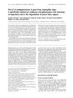
T magnet (LX-9.1M4; GE Medical Systems, Milwaukee,
WI, USA) with the hip and knee maintained in full exten-
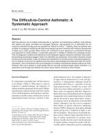
sion (Figure 1). A custom-built ankle loading device (ALD
[25]) supported a dual transmit-receive phased array coil
medial-lateral to the foot, with the coils centered around
the malleoli. The subject's sock-covered foot was
strapped to the freely moving foot-pedal, which allowed
three rotational degrees freedom at the plantar surface of
the forefoot ("ball of the foot") and had a base plate
extending to the mid-calcaneus. The ball of the foot
rested on the foot pedal of the ALD. Plastic stops were
placed in the ALD to limit foot-pedal rotation such that
the subject's motion was maintained in a comfortable,
repeatable range, typically 1-5° less than the subject's
maximum calcaneal- tibial DF-PF range. The external
weight system was adjusted so that a 2.3 kg (5l b) weight
hung freely outside the MR imager, resulting in a resistive
load being applied in calcaneal-tibial PF. The use of a cam
resulted in a fixed moment arm from the rope to the cen-
ter of rotation of the ALD (Figure 1). The loading level
was selected as the level at which all subjects could
smoothly and comfortably perform the task without
reporting fatigue at the end of the trial (based on a pre-
liminary analysis).
A full fast-PC MR image set (x, y, z velocity and ana-
tomic images over 24 time frames) was acquired while the
subjects cyclically repeated a simulated single-leg toe-
raises with partial-weight support for approximately 4
minutes. Subjects were asked to push the pedal down and
release it back to the beat of an auditory metronome
(cycle rate = 35 cycles/minute with 2 beats/cycle). This
motion was not limited to PF-DF, as the three-degree of
freedom pedal allowed the rear-foot joints to move in
internal-external and inversion-eversion, as well. Prior to
data collection, subjects practiced the task until they
could comfortably repeat the motion. Axial cine images
(anatomic images only) were also acquired during the
movement in order to establish bone-based coordinate
systems (Figure 2). Three-dimensional MR images were
acquired and reviewed by a musculoskeletal radiologist to
confirm the absence of foot pathology.
The IHA direction was defined as the unit angular
velocity vector for each joint, expressed relative to the
tibial coordinate system (Figure 2). Unlike other imaging
techniques, fast-PC MRI acquires velocity data directly.
Yet, the bone velocity profiles of specific anatomical
points over time are not known a priori. Thus, the ori-
entation and displacement of the tibia, calcaneus and
talus were individually quantified by integrating velocity
data obtained during the fast-PC acquisition [26]. This
technique has been shown to have excellent accuracy (<
0.5 mm) [27] and subject repeatability (1.3° and 0.9 mm)
[25]. From the orientation data, the direction cosine
(orientation) matrices [talus relative to tibia and calca-
neus relative to both talus and tibia] were defined,
allowing the IHA to be quantified for all three joints
[28].
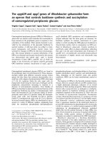
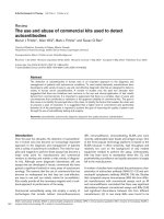
All data were referenced to a tibial coordinate system,
using axial and sagittal images, acquired during rear-foot
supination and pronation (Figure 2), at the time frame
representing the neutral tib-foot angle. The neutral tib-
foot angle was defined as the point in the cycle during
early calcaneal-tibial supination when the tib-foot angle
was as close to zero as possible. The y-axis (ty) was paral-
lel to the anterior aspect of the tibia in the sagittal image.
The temporary tibial z-axis (~tz) was defined as the unit
vector connecting the most lateral and medial tibial
points on the axial image. These points were identified by
finding the point at the greatest concavity on medial mal-
leolus and on the edge of the tibia just anterior to the fib-
ula, respectively. The final coordinate system was
calculated using two cross products in order to ensure a
dextral orthogonal coordinate system. The tibial origin
(To) was defined as the point that bisected the line con-
necting the most lateral and medial tibial points in the
axial image.
Figure 1 Subject placement within the MR imager.
Figure 2 Tibial coordinate system and tib-foot angle.
Sheehan Journal of Foot and Ankle Research 2010, 3:13
/>Page 5 of 10
Once the orientation matrices were defined for the
entire arc of motion, the angular velocity was derived for
each joint of the rear-foot [29,30]:
B1
ω
B2
= ω
x
t
x
+ ω
y
t
y
+ ω
z
t
z
= angular velocity vector of the
body B2 relative to the B1 in the B2 basis.
B1 and B2 = Body 1 and Body 2. For the talocrural joint,
Body 1 = tibia and Body 2 = talus
ω
i
= angular velocity magnitude in the ith direction (i =
x, y, z).
B1
c
B2
= direction cosine matrix
B1
ċ
B2
= its derivative (defined using a centered finite-dif-
ference technique)
The sagittal plane point [28], defined as the point on
the IHA with a medial-lateral location of zero relative to
the tibial coordinate system, represented the IHA loca-
tion. Since the IHA is ill-defined as ω approaches zero,
data were eliminated if ω < 0.3 rad/s. Specifically, when ω
= 0, the sagittal plane point is located at infinity, thus the
cut-off was established so that the IHA maintained a rea-
sonable proximity to the joint for all subjects tested.
For all analyses an orthogonal dextral coordinate sys-
tem was maintained with anterior, superior and right
being positive (x, y and z-directions, respectively), as rec-
ommended by the International Society of Biomechanics
[31,32]. The tibial shaft-to-foot (tib-foot) angle (Figure 2)
was defined to approximate the clinical ankle angle. This
angle was defined as the 90° minus the angle between the
vector parallel to the tibial anterior edge and the vector
from the most posterior-inferior point on the calcaneus
to the inferior metatarsal (typically the third metatarsal).
This calculation allowed a tib-foot angle of 0° to represent
the anatomical neutral position. For averaging and data
presentation the z-direction along with rotations about
the superior and anterior axes were negated for all right
rear-feet such that medial displacement, external rotation
and eversion were positive. DF was presented as a nega-
tive rotation, in order to maintain consistency with stan-
dard clinical notation. The entire movement cycle was
used for all calculations, but data presentation was lim-
ited to calacaneal-tibial supination (defined as the por-
tion of the movement with increasing tib-foot angle).
Since data were taken with respect to time and not the
tib-foot angle, interpolation was used to present data in
single tib-foot angle increments. The translation along
and the rotation about the IHA were derived post-inter-
polation. The range of motion a subject achieved was
self-selected, as this was a volitional exercise requiring
active muscle contraction. Therefore, not all subjects
were represented at the extremes of the range of motion
and average data points representing three or fewer sub-
jects were eliminated from the group average.
Results
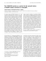
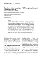
The talocrural and calcaneal-tibial IHAs had similar
directions, predominantly medial-lateral (Figure 3). The
calcaneal-tibial displayed the expected supination pattern
of PF with internal rotation and inversion (Figure 4) as
did the talocrural joint. The medial and anterior direc-
tions of the IHA (indicating PF and inversion, respec-
tively) were fairly consistent throughout the arc of
motion. Yet, the axes became less inferiorly directed as
the calcaneal-tibial joint supinated, (indicating diminish-
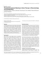
ing internal rotation). The average direction of the subta-
lar IHA did not represent the kinematics well, as its
direction typically changed sign in all three directions at
least once during calcaneal-tibial supination for the
majority of subjects (Figure 4).
The variability in the subtalar IHA resulted in the calca-
neal-tibial joint having a smaller average angular velocity,
relative to the talocrural joint:
The translation along all IHAs was small and tended to
be largest at extreme ranges of tib-foot angle (Figure 5).
Average translations over the arc of motion were -0.5 mm
(SD 1.4), -0.3 mm (SD 1.4) and -0.6 mm (SD 1.4) for the
talocrural, subtalar and calcaneal-tibial joints, respec-
tively. Total rotations about the IHA through the arc of
motion, averaged across subjects, were 31.7° ± (SD 11.3°),
15.1° (SD 9.7°) and 29.1° (SD 8.5°) for the talocrural, sub-
talar and calcaneal-tibial joints, respectively. The variabil-
ity reflects the different ranges of tib-foot angle achieved
by each subject. Since rotation about the IHA is an
unsigned variable, the total rotation about the IHA does
not directly relate to the overall change in orientation,
particularly for the subtalar joint.
The sagittal plane point (Figure 6) was nearly identical
for the talocrural and calcaneal-tibial joint throughout
the range of supination. Its location varied little across
the arc of motion and tended to cross the tibial origin
point in the coronal plane, but remained posterior to it in
the axial and sagittal planes. Adding this result to the
small translation along the IHA indicates that both joints
exhibit primarily rotation during calcaneal-tibial supina-
tion.
BB
zy
zx
yx
BB
T
BB
cc
1 2 12 12
0
0
0
w
ww
ww
ww
=
−
−
−
⎡
⎣
⎢
⎢
⎢
⎤
⎦
⎥
⎥
⎥
=
()
•
w
w
_
_
:
calcaneal tibial
talocrural
84 21 range 53 1 24
−
=± −
()
00 0
w
w
_
_
:
talocrural
subtalar
2 49 78 range 1 5 4 44=± −
()
00
Sheehan Journal of Foot and Ankle Research 2010, 3:13
/>Page 6 of 10
Discussion
One of the primary findings of this study is that the IHA
does not describe subtalar joint kinematics well, for the
specific volitional activity examined, which agrees with
the gait analysis of Arndt and colleagues [23]. The major-
ity of the calcaneal-tibial motion was derived from the
talocrural joint, with the limited subtalar rotations incon-
sistently opposing and supporting this motion. This high-
lights a primary limitation the IHA: it is a velocity
measurement and is, therefore, not defined when the
angular velocity approaches zero. Further, it cannot be
used to define the initial pose of a joint, a major short-
coming as this is often key in defining pathology.
Figure 3 Pictorial representation of the IHA. For the sagittal, coronal, and axial images (left foot) the view is from lateral to medial, anterior to pos-
terior, and distal to proximal, respectively. The maximum DF/PF is shown in the darkest shade of red/green; and the beginning, middle, and end of
the PF cycle is highlighted with a thicker line. For clarity the IHA was graphed at 5° increments of tib-foot angle, instead of single degree increments.
Since all images are of the same scale (280 mm
2
), the length of each IHA represents the actual angular velocity, which directly relates to the amount
of rotation, at that tib-foot angle. The inclination of the IHA is provided (white dashed lines) for the talocrural and the calcaneal-tibial joints at the mid-
range of motion (tib-foot angle = 20° and 25°, respectively).
Sheehan Journal of Foot and Ankle Research 2010, 3:13
/>Page 7 of 10
Arndt and colleagues [23] noted that the subtalar FHA
orientation was quite variable during the gait cycle.
Unfortunately, the data were presented as a single FHA
over the entire gait cycle. Thus, the cycle variability was
not defined. In a static in vivo study, Beimer and col-
leagues [14] found a large variation across subjects in
FHA inclination (Table 1) and location (~120 mm infe-
rior-superior range in the sagittal plane point) when mea-
sured from extreme PF to extreme DF. In addition,
Lundberg and colleagues [16] demonstrated a high vari-
ability in the inclination of the subtalar FHA when quan-
tified at different ranges of PF. Taken together, these
studies support the high variability of subtalar IHA orien-
tation and position observed across subjects and across
the arc of motion. The majority of cadaver studies that
quantified the FHA between maximum DF and maxi-
mum PF have shown good agreement (Table 1) with
Inman's original publication [11] of a subtalar FHA incli-
nation, with fairly low variability. This consistency is
likely due to the fact that these past studies typically
defined the FHA between two maximum joint positions
(e.g., maximum inversion to maximum eversion or maxi-
mum PF to maximum DF). Thus, direct comparisons to
these past studies are difficult and the variability reported
for the subtalar IHA is likely due to the presence of active
muscle control and the intact nature of the joints studies
(often some or all of the soft tissue is removed during
cadaver studies).
This is the first study to report complete rear-foot kine-
matics, based on the IHA, throughout a range of motion
during a voluntary motion under active muscle control.
To d ate , only tw o stud ie s h ave re por te d in vivo talocrural
joint kinematics [23,25], based on the FHA, during voli-
tional activity. Arndt and colleagues [23] defined the FHA
as the change in joint attitude from the beginning to the
end of calcaneal-tibial PF during the gait cycle. Their lim-
ited the range of calcaneal-tibial PF (13.5°, the range of
calcaneal-tibial PF is ~30° during gait [33]) was likely due
to soft tissue impingement on bone pins or anesthesia.
Despite these differences, the sagittal and axial plane
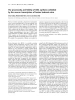
Figure 4 Unit joint angular velocities. which define the IHA direction. Pure supination occurs when all components fall within the grey areas. One
SD bars are provided every 5°, except for the subtalar joint, where each subject is represented by a unique line color (due to the rapidly changing
direction of the subtalar IHA, creating a subject average did not represent the data well).
Sheehan Journal of Foot and Ankle Research 2010, 3:13
/>Page 8 of 10
inclination of the talocrural FHA was similar to the cur-
rent results (Table 1). The rotations about the FHA were
smaller in the previous study, likely due to the smaller arc
of motion. In addition, the current data agree well with
other previous cadaver studies in terms of the talocrural
orientation (Table 1).
The translational component of motion has not been a
focus of most previous studies. Yet, it is important to
appreciate the small translation of the IHA and the small
translation along the IHA for both the talocrural and cal-
caneal-tibial joints. These small translations indicate that
the IHA is excellent descriptor for talocrural and calca-
neal-tibial kinematics and that these joints can be mod-
eled as fixed hinge joints. A more precise model would
incorporate the small changes in IHA inclination and the
small translation throughout the arc of motion.
The fact that the IHA the talocrural joint was depicted
as being slightly more superior and posterior than previ-
ous reports [16] is most likely due to the motion studied.
The current study focused on volitional activity requiring
active muscle control, which may have allowed for greater
translation of the IHA and translation along the IHA.
Such a translation would maintain joint congruency with
the IHA being slightly outside of the talus bone. Further,
the average IHA was superimposed onto the images from
a single subject. Thus, the visual interpretation relative to
the bones is an approximation, as an average set of bones
was not used to display the average IHA.
The primary limitation of this study was the fact that
the IHA was defined for emulated partial-weight bearing,
instead of full-weight bearing. This was necessary in
order to exclude fatigue and maintain volunteer comfort.
As open MR imaging technology improves, experiments
including full-weight bearing will become available. The
non-invasive dynamic nature of this experiment, its abil-
ity to incorporate muscle control and its excellent accu-
racy/subject-repeatability justify this potential limitation.
This study is limited in its ability to define translations
along the IHA, as the overall translations were within the
same range as the accuracy of the technique. The vari-
ability in the subtalar IHA was not due to an inability to
measure a small bone, such as the talus, with dynamic
MR imaging. This is evidenced by the consistent results
for the talocrural IHA, which defines the motion of the
Figure 5 Translation along and rotation about the IHA. One stan-
dard deviation bars are provided every five degrees of tib-foot angle,
instead of every degree increments, for clarity.
Figure 6 The sagittal plane points of the IHA. One standard devia-
tion bars are provided every five degrees of tib-foot angle, instead of
every degree, for clarity. The top and bottom graphs represent the su-
perior-inferior and anterior-posterior location, respectively, of the sag-
ittal plane point.
Sheehan Journal of Foot and Ankle Research 2010, 3:13
/>Page 9 of 10
talus relative to the fairly stationary tibia, and by the
excellent subject-repeatability in measuring talar motion
[25]. Thus, the variability quantified is due to the true
variability of the subtalar FHA both across subjects and
throughout the arc of motion.
Conclusions
The current study provides a basis for the development of
improved surgical and rehabilitative protocols by estab-
lishing a normative database of rear-foot joint kinematics
(represented by the IHA), acquired during a partial-
weight bearing functional task. The differences between
the current study and past static studies are likely due to
the dynamic nature of the experiment, the required mus-
cle activity and the inclusion of full three-dimensional
rear-foot movement. The excellent subject-repeatability,
high accuracy and clearly-defined coordinate systems
make these data readily available for experimental com-
parison, modeling input and device design. Additionally,
the experimental paradigm can easily be used to study
impairments and the effects of intervention. In this rela-
tively large asymptomatic population, it was obvious that
the primary motion of the rear-foot (during emulated
toe-raise with partial-weight support) is derived from the
talocrural joint. Rotation at the subtalar joint is inconsis-
tent and can work in both harmony and opposition to the
talocrural joint in creating overall tibio-calcaneal joint
movement.
Competing interests
The author declares that they have no competing interests.
Acknowledgements
A presentation based on this work won the Best Paper Award at the 2008 Inter-
national Foot and Ankle Biomechanics meeting (iFAB) in Bologna. I wish to
thank Andrea R. Seisler and Tracy Rausch for the assistance in device design &
fabrication along with data collection. I would like to thank Steven Stanhope,
PhD, for guidance throughout the project. I would also like to thank Bonnie
Damaska, Jamie Fraunhaffer, Jere McLucas and the Diagnostic Radiology
Department at the National Institutes of Health for their support and research
time. Any opinions, findings, and conclusions or recommendations expressed
in this material are those of the author and do not necessarily reflect the views
of the National Institutes of Health or the US Public Health Service. This
research was supported in part by the Intramural Research Program of the NIH,
(CC and NICHD).
Author Details
Functional and Applied Biomechanics Section, Rehabilitation Medicine
Department, National Institutes of Health, Bethesda, MD, USA
References
1. Bozkurt M, Doral MN: Anatomic factors and biomechanics in ankle
instability. Foot Ankle Clin 2006, 11:451-463.
2. Daniels T, Thomas R: Etiology and biomechanics of ankle arthritis. Foot
Ankle Clin 2008, 13:341-52. vii
3. Karlsson J, Sancone M: Management of acute ligament injuries of the
ankle. Foot Ankle Clin 2006, 11:521-530.
4. Chou LB, Coughlin MT, Hansen S Jr, Haskell A, Lundeen G, Saltzman CL,
Mann RA: Osteoarthritis of the ankle: the role of arthroplasty. J Am Acad
Orthop Surg 2008, 16:249-259.
5. Leardini A, O'connor JJ, Catani F, Giannini S: Mobility of the human ankle
and the design of total ankle replacement. Clin Orthop Relat Res
2004:39-46.
6. O'Loughlin PF, Hodgkins CW, Kennedy JG: Ankle sprains and instability
in dancers. Clin Sports Med 2008, 27:247-262.
7. Gougoulias NE, Khanna A, Maffulli N: History and evolution in total ankle
arthroplasty. Br Med Bull 2009, 89:111-151.
8. Wood PL, Clough TM, Smith R: The present state of ankle arthroplasty.
Foot Ankle Surg 2008, 14:115-119.
9. Root ML, Weed JH, Sgarlato TW, Bluth DR: Axis of motion of the subtalar
joint: An anatomical study. J Am Acad Orthop Surg 1966, 56:149-155.
10. Manley MT: Biomechanics of the Foot. Disorders of the Foot 1980:21-30.
11. Inman VT: Inman's Joints of the Ankle Williams & Wilkins; 2002.
12. Leardini A, Stagni R, O'connor JJ: Mobility of the subtalar joint in the
intact ankle complex. J Biomech 2001, 34:805-809.
13. Manter JT: Movements of the subtalar and transverse tarsal joints. Anat
Rec 1941, 80:397-410.
14. Beimers L, Tuijthof GJ, Blankevoort L, Jonges R, Maas M, van Dijk CN: In-
vivo range of motion of the subtalar joint using computed
tomography. J Biomech 2008, 41:1390-1397.
15. Siegler S, Udupa JK, Ringleb SI, Imhauser CW, Hirsch BE, Odhner D, Saha
PK, Okereke E, Roach N: Mechanics of the ankle and subtalar joints
revealed through a 3D quasi-static stress MRI technique. J Biomech
2005, 38:567-578.
16. Lundberg A, Svensson OK, Nemeth G, Selvik G: The axis of rotation of the
ankle joint. J Bone Joint Surg Br 1989, 71:94-99.
17. Pearce TJ, Buckley RE: Subtalar joint movement: Clinical and computed
tomography scan correlation. Foot Ankle Int 1999, 20:428-432.
18. Dul J, Shiavi R, Green NE: Simulation of tendon transfer surgery. Eng
Med 1985, 14:31-38.
19. Gauffin H, Areblad M, Tropp H: 3-Dimensional Analysis of the Talocrural
and Subtalar Joints in Single-Limb Stance. Clin Biomech 1993,
8:307-314.
20. Procter P, Paul JP: Ankle joint biomechanics. J Biomech 1982, 15:627-634.
21. van den Bogert AJ, Smith GD, Nigg BM: In vivo determination of the
anatomical axes of the ankle joint complex: an optimization approach.
J Biomech 1994, 27:1477-1488.
22. Close JR, Inman VT, Poor PM, Todd FN: The function of the subtalar joint.
Clin Orthop Relat Res 1967, 50:159-179.
23. Arndt A, Westblad P, Winson I, Hashimoto T, Lundberg A: Ankle and
subtalar kinematics measured with intracortical pins during the stance
phase of walking. Foot Ankle Int 2004, 25:357-364.
24. Woltring HJ, Huiskes R, Delange A, Veldpaus FE: Finite Centroid and
Helical Axis Estimation from Noisy Landmark Measurements in the
Study of Human Joint Kinematics. J Biomech 1985, 18:379-389.
25. Sheehan FT, Seisler AR, Siegel KL: In vivo talocrural and subtalar
kinematics: A non-invasive 3D dynamic MRI study. Foot Ankle Int 2007,
28:323-335.
26. Sheehan FT, Zajac FE, Drace JE: In vivo tracking of the human patella
using cine phase contrast magnetic resonance imaging. J Biomech Eng
1999, 121:650-656.
27. Sheehan FT, Zajac FE, Drace JE: Using cine phase contrast magnetic
resonance imaging to non-invasively study in vivo knee dynamics. J
Biomech 1998, 31:21-26.
28. Sheehan FT: The Finite Helical Axis of the Knee Joint (a non-invasive in
vivo study using fast-PC MRI). J Biomech 2007, 40:1038-47.
29. Kane TR, Likins PW, Levinson DA: Spacecraft Dynamics New York: McGraw-
Hill Book Company; 1983.
30. Woltring HJ: 3-D Attitude Representation of Human Joints - A
Standardization Proposal. J Biomech 1994, 27:1399-1414.
31. Wu G, Siegler S, Allard P, Kirtley C, Leardini A, Rosenbaum D, Whittle M,
D'Lima DD, Cristofolini L, Witte H, et al.: ISB recommendation on
definitions of joint coordinate system of various joints for the reporting
of human joint motion part I: ankle, hip, and spine. International
Society of Biomechanics. J Biomech 2002, 35:543-548.
32. Sheehan FT, Mitiguy P: In regards to the "ISB recommendations for
standardization in the reporting of kinematic data". J Biomech 1999,
32:1135-1136.
Received: 21 June 2010 Accepted: 13 July 2010
Published: 13 July 2010
This article is available from: 2010 Sheehan; licensee BioMed Central Ltd. This is an Open Access article distributed under the terms of the Creative Commons Attribution License ( ), which permits unrestricted use, distribution, and reproduction in any medium, provided the original work is properly cited.Journal of Foot and Ankle Research 2010, 3:13
Sheehan Journal of Foot and Ankle Research 2010, 3:13
/>Page 10 of 10
33. Gundersen LA, Valle DR, Barr AE, Danoff JV, Stanhope SJ, Snydermackler L:
Bilateral Analysis of the Knee and Ankle During Gait - An Examination
of the Relationship Between Lateral Dominance and Symmetry. Phys
Ther 1989, 69:640-650.
doi: 10.1186/1757-1146-3-13
Cite this article as: Sheehan, The instantaneous helical axis of the subtalar
and talocrural joints: a non-invasive in vivo dynamic study Journal of Foot and
Ankle Research 2010, 3:13