Advanced Strategies For Robot Manipulators Part 3 pdf
Bạn đang xem bản rút gọn của tài liệu. Xem và tải ngay bản đầy đủ của tài liệu tại đây (2.17 MB, 30 trang )
Hyper Redundant Manipulators
51
Fig. 13. Camera looks to the center of the circle
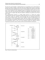
How to “move” the camera according to the steps of these algorithms? The image behavior
in accordance with camera’s movements was studied. The effect of pan and tilt rotations on
two points placed in a quadratic position on a circle was geometrically described.
Coordinate transformation matrices corresponding to rotations with pan and tilt angles,
respectively for perspective transformation were used. The variation of the distance between
the two points, placed in a quadratic position on the circle, and the centre of the circle,
depending of the tilt angle X, is plotted bellow in Fig. 14.
Fig. 14. Distance variation for quadratic positions
The variation of the ratio of the two distances is plotted bellow in Fig. 15a. The plot from
Fig. 15b shows how is transformed a rectangle (inscribed in the circle and having the edges
parallel with the axes OX and OY) when a tilt rotation is performed. Theoretically, by
zooming, the distance between the two points varies in a linear way, as it is shown upper
right.
The image’s segmentation is basically a threshold procedure applied to the image’s
histogram. All the procedures included in the calibration algorithms were mathematically
proven. If the calibration algorithm was successfully applied then the system is ready to
perform the visual servoing tasks.
0 0.5 1 1.5
0
5
10
15
FRx1 f α, ( ) FRx0 f α, ()−
α
0 0.5 1 1.5
0
1
2
3
4
5
6
FRx2 f α, ( ) FRx0 f α, ()−
α
Advanced Strategies for Robot Manipulators
52
Fig. 15. a. Ratio distances variation b. Rectangle transformation and distance variation under
zoom influence
5. A Compliance control of a hyper redundant robot
This section treats a class of hyper redundant arms can achieve any position and orientation
in 3D space, and that can perform a coil function for the grasping. The arm is a high degree
of freedom structure or a continuum structure, but in this chapter a different technological
solution is assumed.
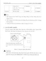
The general form of the arm is shown in Figure 16. It consists of a number (N) of elements,
cylinders made of fibre-reinforced rubber.
Fig. 16. The force sensors distribution
There are four internal chambers in the cylinder, each of them containing the ER fluid with
an individual control circuit. The deformation in each cylinder is controlled by an
independent electrohydraulic pressure control system combined with the distributed
control of the ER fluid.
The last m elements (
m < N) represent the grasping terminal. These elements contain a
number of force sensors distributed on the surface of the cylinders. These sensors measure
the contact with the load and ensure the distributed force control (Singh & Popa, 2005)
during the grasping. The theoretical model is described as in Fig. 7 and equation (26)-(33).
For an element
dm, kinetic and gravitational potential energy will be:
0
Y
X
Z
Force sensors
Force sensors
0 0.5 1 1.5
1
1.1
1.2
1.3
1.4
1.5
FRx1 f α, ( ) FRx0 f α, ()−
FRx2 f α, ( ) FRx0 f α, ()−
α
2− 1− 0 1 2
3−
2−
1−
0
1
2
yp
i
yn
i
xp
i
xn
i
,
Hyper Redundant Manipulators
53
(
)
2
z
2
y
2
x
vvvdm
2
1
dT ++= , zgdmdV
⋅
⋅
=
(101)
where
dsdm ⋅=
ρ
, and
ρ
is the mass density.
The elastic potential energy will be approximated by the bending of the element:
()
θ
=
=+
∑
2
22
1
4
N
eii
i
d
Vk q
(102)
We will consider
(
)
t,sF
θ
,
(
)
t,sF
q
the distributed forces on the length of the arm that
determine motion and orientation in the
θ
-plane,
q
-plane. The mechanical work is:
()() ()()
()
∫∫
+=
l
0
t
0
q
dsd,sq,sF,s,sFL
ττττθτ
θ
(103)
The energy-work relationship will be
()() ()()
()
∫∫
+=
l
0
t
0
q
dsd,sq,sF,s,sFL
ττττθτ
θ
(104)
where
()
tT and
(
)
0T ,
(
)
tV
∗
and
(
)
0V
∗
are the total kinetic energy and total potential
energy of the system at time
t and 0, respectively.
In this chapter, the manipulator model is considered as a distributed parameter system
defined on a variable spatial domain
[
]
L,0
=
Ω
and the spatial coordinate s.
From (101-103), the distributed parameter model becomes,
()()(
()
()
()
()
()
()
())
q
S
0
2
2
S
0
S
0
Fqksdqcosgsdsdqqsinqq
cosqsinqcosqcosqsincosqsinqcosq
sinqsinqcosqcosqcosqqcosqsinqsinq
=+
′′
+
′′′′
−
′′′′′
−
−
′′
−
′′′′′
+
′′′
−
′′
−
′′′′′
+
+
′
−
′′′′′′
−
′′′
+
′′
−
′′′′′
∗
∫
∫∫
ρ
θθθθθ
θθθρ
(105)
()
(
()
()
()
()
() ()
)
θ
θθθθθθθ
θθθθθθθρ
Fksdsdcosqcosqsinqsinqcosqcos
sinqcosqcosqcosqcosqcossinqcosqsinq
2
2
S
0
S
0
=+
′′′′
−
′′′′′′′
−
′
−
′′′′′′
+
+
′
−
′′′′′′
−
′
−
′′′′′′
+
′
−
′′′′′′
∗
∫∫
(106)
The control forces have the distributed components along the arm,
()
t,sF
θ
,
()
t,sF
q
,
[
]
L,0s∈ that are determined by the lumped torques,
() ( )()
() ( )()
⎪
⎪
⎩
⎪
⎪
⎨
⎧
−=
−=
∑
∑
=
=
N
1i
N
1i
tilst,sF
tilst,sF
i
i
τδ
τδ
θθ
(107)
Advanced Strategies for Robot Manipulators
54
where
δ
is Kronecker delta, llll
N21
=
=
=
=
… , and
(
)
(
)
8dSppt
21
iii
⋅−=
θθθ
τ
(108)
(
)
(
)
8dSppt
2
q
1
iii
⋅−=
τ
,
N,,2,1i …
=
(109)
In (107)-(108),
1
i
p
θ
,
2
i
p
θ
,
1
q
i
p ,
2
q
i
p represent the fluid pressure in the two chamber pairs,
θ
, q
and
S, d are section area and diameter of the cylinder, respectively (Fig. 17).
Fig. 17. The cylinder driving
The pressure control of the chambers is described by the equations:
()
ki
k
i
ki
u
dt
dp
a
θ
θ
θ
= (110)
()
qki
k
qi
ki
u
dt
dp
qb =
,
2,1k
=
,
N,,2,1i …
=
(111)
where
()
θ
ki
a ,
(
)
qb
ki
are determined by the fluid parameters and the geometry of the
chambers and
(
)
00a
ki
> ,
(
)
00b
ki
> (112)
The control problem of a grasping function by coiling is constituted from two subproblems:
the position control of the arm around the object-load and the force control of grasping
(Chiaverini et al., (1996). We consider that the initial state of the system is given by
(
)
[
]
T
000
q,s,0
θωω
==
(113)
corresponding to the initial position of the arm defined by the curve
0
C
(
)
(
)
(
)
sq,s:C
000
θ
,
[
]
L,0s
∈
(114)
E R F
Li
θ
τ
i
u
1
θ
i
u
2
θ
r
r
2
i
p
θ
1
i
p
θ
Hyper Redundant Manipulators
55
Fig. 18. (a) The grasping position; (b) The grasping parameters
The desired point is represented by a desired position, the curve
C
d
that coils the load,
[
]
T
ddd
q,
θω
=
(115)
(
)
(
)
(
)
sq,s:C
ddd
θ
,
[
]
L,0s∈ (116)
In a grasping function by coiling, only the last m elements (
m < N) are used. Let l
g
be the
active grasping length, where
∑
=
=
n
mi
ig
ll . We define by
(
)
te
p
the position error
() ( ) ()
()
() ()
()()
∫
−
−+−=
L
lL
bbp
g
dssqt,sqst,ste
θθ
(117)
It is difficult to measure practically the angles
θ
, q for all
[
]
L,0s∈
. These angles can be
evaluated at the terminal point of each element. In this case, the relation (117) becomes
() ()
()
()
()()
∑
=
−+−=
N
mi
biibiip
qtqtte
θθ
(118)
The error can also be expressed with respect to the global desired position
C
d
() ()
()
()
()()
∑
=
−+−=
N
1i
diidiip
qtqtte
θθ
(119)
The position control of the arm means the motion control from the initial position
C
0
to the
desired position
C
d
in order to minimize the error. An area reaching control problem is
discussed. The desired area is specified by the inequality function:
(
)
0rf
≤
δ
(120)
where
f is a scalar function with continuous first partial derivates,
δ
=
−
0F
rr r,
3
0
Rr ∈ is a
reference point of the desired area and
F
r is the position vector of the terminal point.
The potential energy function for the area reaching control has the form:
() () ()
()
⎟
⎟
⎠
⎞
⎜
⎜
⎝
⎛
⋅
∂
∂
−−−=
∗∗
iiP
T
P
2
q,ak
r
V
,0maxtektekt
i
iiiii
θτ
θ
θθθθθ
(121)
(a)
Grasping
elements
load
Initial
Position (C
0
)
Desired
Position (C
d
)
F
id
X
0
b
C
b
s
(b)
Advanced Strategies for Robot Manipulators
56
Theorem 1.
The closed-loop control system for the desired reaching area problem is stable if
the control forces are
(
)
(
)
(
)
(
)
(
)
iiP
T
P
2
q,akrV,0maxtektekt
i
iiiii
θτ
θ
θθθθθ
∗∗
⋅∂∂−−−=
(122)
(
)
(
)
(
)
(
)
(
)
iiP
T
P
2
qqqq
q,akrV,0maxtektekt
i
qiiiii
θτ
θ
∗∗
⋅∂∂−−−=
(123)
Theorem 2. The closed-loop control system of the position (107)-(108), (110)-(111) is stable if
the fluid pressures control law in the chambers of the elements given by:
(
)
(
)
(
)
(
)
(
)
θθθθθ
θ
=− +
12jj
ji ji i i i i
ut a ketket (124)
() ( ) () ()
(
)
θ
=− +
12jj
qji ji qi qi qi qi
ut b ket ket
(125)
where
2,1j = ;
N,,2,1i …=
, with initial conditions:
(
)
(
)
(
)
(
)
θθ θθθ
−=−
12 1121
00 0
ii iii
pp kke (126)
() ()
(
)
()
−=−
12 1121
00 0
qi qi qi qi qi
pp kke (127)
(
)
θ
=
00
i
e (128)
(
)
=
00
qi
e , N,,2,1i …= (129)
and the coefficients
θ
i
k ,
q
i
k ,
θ
mn
i
k ,
mn
q
i
k are positive and verify the conditions
21
i
11
i
kk
θθ
>
;
22
i
12
i
kk
θθ
>
(130)
21
qi
11
qi
kk > ;
22
qi
12
qi
kk > , N,,2,1i …
=
(131)
The grasping by coiling of the continuum terminal elements offers a very good solution in
the fore of uncertainty on the geometry of the contact surface. The contact between an
element and the load is presented in Fig. 19. It is assumed that the grasping is determined
by the chambers in
θ
-plane. The relation between the fluid pressure and the grasping forces
can be inferred for a steady state from,
(
)
() () ()
()
θ
θθ
∂
+=−
∂
∫∫∫
2
12
2
000
8
lls
T
s
d
kdsfsTsTsdsppS
s
(132)
where
()
sf is the orthogonal force on
b
C ,
(
)
sf is
(
)
sF
θ
in
θ
-plane and
(
)
sF
q
in q-plane.
For small variation
i
θΔ
around the desired position
id
θ
, in
θ
-plane, the dynamic model
(118) can be approximated by the following discrete model,
(
)
(
)
(
)
eiiididdidiidiiiii
Ffdq,Hq,,Hcm −=−+++
θθθΔθθΔθΔ
(133)
Hyper Redundant Manipulators
57
Fig. 19. The grasping force
Fig. 20. The block scheme of the control system
where
Δ
ρ
Sm
i
= ,
1
l,,2,1i …
=
.
(
)
did
q,H
θ
is a nonlinear function defined on the desired
position
()
did
q,
θ
,
(
)
diii
q,,cc
θν
=
,
0c
i
>
,
(
)
ΩΓθ
∈q,
, where
ν
is the viscosity of the
fluid in the chambers. The equation (133) becomes:
(
)
(
)
(
)
eiiiididiidiiii
Ffdq,hq,,cm −=⋅++
θΔθθΔθνθΔ
(134)
The aim of explicit force control is to exert a desired force
id
F . If the contact with load is
modelled as a linear spring with constant stiffness
L
k , the environment force can be
modelled as
iLei
kF
θ
Δ
= . The error of the force control may be introduced as
idiefi
FFe
−
=
(135)
It may be easily shown that the equation (134) becomes
idi
i
iifii
i
fi
L
i
fi
L
i
Fd
k
h
fded
k
h
e
k
c
e
k
m
⎟
⎠
⎞
⎜
⎝
⎛
+−=
⎟
⎠
⎞
⎜
⎝
⎛
+++
(136)
Theorem 3. The closed force control system is asymptotic stable if the control law is
(
)
()
(
)
idiLifi
2
iiLi
iL
i
Fdkhemdkh
dk
1
f −−++=
σ
,
σ
ii
mc >
(137)
s
i
s
i+1
Δ
f
i
k
L
Load
Grasping
element
F
id
Eq(135), (136)
e
fi
f
i
E
q(
137
)
υ
Δθ
i
+
F
ie
Transducer
Advanced Strategies for Robot Manipulators
58
6. Conclusion
The research group from the Faculty of Automation, Computers and Electronics, University
of Craiova, Romania, started working in research field of hyper redundant robots over 25
years ago. The experiments used cables and DC motors or stepper motors. The rotation of
these motors rotates the cables which by correlated screwing and unscrewing of their ends
determine their shortening or prolonging, and by consequence, the tentacle curvature.
The inverse kinematics problem is reduced to determining the time varying backbone curve
behaviour. New methods for determining “optimal” hyper-redundant manipulator
configurations based on a continuous formulation of kinematics are developed.
The difficulty of the dynamic control is determined by integral-partial-differential models
with high nonlinearities that characterize the dynamic of these systems. First, the dynamic
model of the system was inferred. The method of artificial potential was used for these
infinite dimensional systems. In order to avoid the difficulties associated with the dynamic
model, the control law was based only on the gravitational potential and a new artificial
potential.
The control system is an image – based visual servo control. Servoing was based on
binocular vision, a continuous measure of the arm parameters derived from the real-time
computation of the binocular optical flow over the two images, and is compared with the
desired position of the arm. The method is based on the particular structure of the system
defined as a “backbone with two continuous angles”. The control of the system is based on
the control of the two angles. The error angle was used to calculate the spatial error and a
control law was synthesized. The general control method is an image based visual servoing
one instead of position based. By consequence, camera calibration based on intrinsic
parameters is not necessary („calibration“ in the classic sense of the term, not the one used
in this paper). The term “camera calibration” in the context of this paper refers to
positioning and orienting the two cameras at imposed values. This calibration is performed
only at the beginning, after that the cameras remain still.
A new application investigates the control problem of a class of hyper-redundant arms with
continuum elements that performs the grasping function by coiling. The control problem of
a grasping function by coiling is constituted from two subproblems: the position control of
the arm around the object-load and the force control of grasping.
7. Acknowledgement
The research presented in this paper was supported by the Romanian National University
Research Council CNCSIS through the IDEI Research Grant ID93 and by FP6 MARTN
through FREESUBNET Project no. 36186.
8. References
Blessing, B.; & Walker, I.D. (2004). Novel Continuum Robots with Variable- Length Sections,
Proc. 3rd IFAC Symp. on Mechatronic Systems, Sydney, Australia, pp. 55-60.
Boccolato, G.; Dinulescu, I.; Predescu, A.; Manta, F.; Dumitru, S.; & Cojocaru, D.; (2010). 3D
Control for a Tronconic Tentacle,
12
th
International Conference on Computer Modelling
and Simulation,
p380-386, ISBN 978-0-7695-4016-0,
Hyper Redundant Manipulators
59
Cambridge University, England.
Ceah, C.C. & Wang, D.Q. (2005). Region Reaching Control of Robots: Theory and
Experiments,
Proceedings of IEEE Intl Conf on Rob. and Aut., Barcelona,
pp. 986-991.
Chiaverini, C.; Siciliano, B. & Villani, L. (1996). Force and Position Tracking: Parallel Control
with Stiffness Adaptation,
IEEE Control Systems, Vol. 18, No 1, pp. 27-33.
Chirikjian, G.S. (1993). A continuum approach to hyper-redundant manipulator dynamics,
Proc. 1993 Int. Conf. on Intelligent Robots and Syst., Yokohama, Japan,
pp. 1059 - 1066.
Cojocaru, D.; Ivanescu, M.; Tanasie, R.T.; Dumitru, S.; Manta, F. (2010), Vision Control for
Hyperredundant Robots,
International Journal Automation Austria (IJAA), ISSN 1562-
2703, IFAC-Beirat Österreich, Vol. 1, 18(2010), p52-66.
Cowan, L. S. & Walker, I.D., 2008. “Soft” Continuum Robots: the Interaction of Continuous
and Discrete Elements,
Artificial Life X.
Douskaia, N.V. (1998). Artificial potential method for control of constrained robot motion,
IEEE Trans. on Systems, Man and Cybernetics, part B, vol. 28, pp. 447-453.
Ge, S.S.; Lee, T.H. & Zhu, G. (1996). Energy-Based Robust Controller Design for Multi-Link
Flexible Robots,
Mechatronics, No 7,Vol. 6, pp. 779-798.
Gravagne, I. D. & Walker, I.D. (2001). Manipulability, force, compliance analysis for planar
continuum manip,
Proc. IEEE/RSI Intl. Conf. o Intell. Rob. and Syst., pp. 1846-1867.
Grosso, E.; Metta, G. & a.o. (1996). Robust Visual Servoing in 3D Reaching Tasks,
IEEE
Transactions on Robotics and Automation
, vol. 12, no. 15, pp. 732-742.
Hannan, M.W. & Walker, I.D. (2005). Real-time shape estimation for continuum robots using
vision,
Robotica, volume 23, pp. 645–651.
Hemami, A, (1984). Design of light weight flexible robot arm,
Robots 8 Conference
Proceedings
, Detroit, USA, pp. 1623-1640.
Hirose, S. (1993).
Biologically Inspired Robots, Oxford University Press.
Hutchinson, S.; Hager, G. D. & Corke, P. F. (1996). A Tutorial on Visual Servor Control,
IEEE
Transactions on Robotics and Automation
, vol. 12, no. 15, pp. 651-670.
Immega, G. & Antonelli, K. (1995). The KSI Tentacle Manipulator.
Proc. 1995 IEEE Conf. on
Robotics and Automation
, pp. 3149-3154.
Ivănescu, M.; Cojocaru, & a.o. (2006). Hyperredundant Robot Control by Visual Servoing,
Studies in Informatics and Control Journal, Vol. 15, No. 1, ISSN 1220-1766, p93-102.
Ivanescu, M. (2002). Position dynamic control for a tentacle manipulator,
Proc. IEEE Int.
Conf. on Robotics and Automation
, Washington, A1-15, pp. 1531-1539.
Kelly, R. (1996), Robust Asymptotically State Visual Servoing,
Proceedings IEEE Inernational
Conference on Robotics and Automation
, vol. 22, no. 15, pp. 759-765.
Masoud, S. A. & Masoud, A.A. (2000). Constrained motion control using vector potential
fields,
IEEE Trans. on Systems, Man and Cybernetics, part A, vol. 30, pp. 251-272.
Mochiyama, H. & Kobayashi, (1999). H. The shape Jacobian of a manip with hyper degrees
of freedom,
Proc. 1999 IEEE Intl. Conf. on Rob. and Autom., Detroit, pp. 2837- 2842.
Robinson, G. & Davies, J. B. C. (1999). Continuum robots—A state of the art.
In IEEE
International Conference on Robotics and Automation
, pages 2849–2854. Detroit, MI.
Advanced Strategies for Robot Manipulators
60
Singh, S.K. & Popa, D.O. (2005) An Analysis and Some Fundamental Problems in
Adaptive Control of Force,
IEEE Trans. on Robotics and Automation, Vol. 11 No 6, pp
912-922.
Suzumori, K.; Iikura, S.; & Tanaka, H. (1991). Develop. of flexible microactuator and its appl.
to robot mech,
IEEE Intl. Conf. on Rob. and Autom., Sacramento, pp. 1564 - 1573.
Takegaki, T.; & Arimoto, S. (1981). A new feedback methods for dynamic control of
manipulators,
Journal of Dynamic Systems, Measurement and Control, pp. 119-125.
Tanasie, R.T.; Ivănescu, M. & Cojocaru, D. (2009). Camera Positioning and Orienting for
Hyperredundant Robots Visual Servoing Applications,
Journal of Control
Engineering and Applied Informatics
, ISSN 1454-8658, Vol 11, No 1, p19-26.
Walker, I.D., Dawsona, D.M. & a.o. (2005), Continuum Robot Arms Inspired by
Cephalopods, DARPA Contr. N66001-C-8043, .
Walker, I.D. & Carreras, C. (2006) Extension versus Bending for Continuum Robots,
Internl.
Journal of Advanced Robotic Systems
, Vol. 3, No.2, ISSN 1729-8806, pp. 171-178.
Wang, P.C. (1965). Control of distributed parameter systems,
Advance in Control Systems,
Academic Press.
3
Micro-Manipulator for Neurosurgical Application
M. R. Arshad and Ya’akob Yusof
Underwater Robotics Research Group (URRG),
School of Electrical and Electronics Engineering, Universiti Sains Malaysia,
Malaysia
1. Introduction
Neurosurgery is a part of the surgical field that focused in taking care of the diseases related
to human’s central peripheral nervous system and also their central spinal cord [20]. The
term surgery refers to the operation of peripheral nervous system as well as the spinal cord,
brain, blood vessel connected to it, spine, spinal cord, and also nerves that control our senses
and body’s movement [29]. There are lots of neuro diseases, which among them were brain
tumors, head trauma, stroke, thalamic astrocytomas, and spinal cord trauma. These
diseases, if not thrown away, will results the patient in body disorder, health problem, and
of course, death. To put an end to these disorders, appropriate treatment is mandatory.
Those diseases need to be cured and removed. Surgery, or specifically neurosurgery, is one
of the effective methods to treat it.
Neurosurgery comes with risks. Any operation dealing with brain or the spinal cord can
cause paralysis, brain damage, infection, psychosis, or even death if a mistake happens.
These operations are also likely to cause mental impairment as of any surgical procedure
dealing with the brain. Therefore, it is vital for neurosurgeon to make sure that this kind of
surgery is performed in an almost perfect condition to minimize any risks or poor results as
the consequences from it. Traditionally, starting from scalp removing, drilling and removing
the skull, handling the lump, until sewing the skull and scalp back at its original location;
surgeons put their efforts with their own hands and bare eyes. Tools and equipments did
improved, for example with the usage of apparatus such as top-mount microscope and
magnetic resonance imaging (MRI) machine. However, they still need to manipulate the
surgical tools, the closest tools to the human brain, such as the knife and biopsy needles
with naked hands. As a results, it will surely introduced limits to the tools manipulation.
This is where robots can do a lot better. A very precise robotic device that can perform
manipulation at much smaller or micro scale, plus the capability of the surgeon himself, will
produce much superior results. These robotic devices are termed surgical micro-
manipulator.
This chapter presents readers with information regarding the design of a micro-manipulator
purposely for neurosurgical application. It also shares beneficial facts and particulars
regarding current progress about micro-manipulator research around the globe. This
chapter is organized as the following: Section 2 provides details justification of designing a
robotic hand in an operating room based on the constraints for a neurosurgical procedures.
Section 3 will discuss design considerations for a micro-manipulator for neurosurgery. This
Advanced Strategies for Robot Manipulators
62
includes the important hardware and software elements that contributed to the build-up of
a micromanipulator. Section 4 briefly shares on the design and uniqueness of one of the
recent and successful micro-manipulator for neurosurgical application. Section 5 will finally
conclude this article.
(a) (b)
Fig. 1. (a) Graphical illustration of brain tumor. A primary brain tumor is a mass created by
the growth or uncontrolled proliferation of cells in the brain. (b) Spinal tumor
2. Why robotics
Fig. 2. Da Vinci® tele-surgical system.
The idea of having robots inside the operation theatre is basically to assist the neurosurgeon
perform the surgery. Fatigue experienced by surgeons, post-surgery trauma on the patient
and human errors are among the challenges faced during neurosurgical operation [10].
According to [6], there are studies being done that shows during a long surgical operation,
there will be substantial muscle fatigue. Neurosurgical or any surgical procedure usually
takes a very long time, thus will decrease the effectiveness of a surgeon. In contrast, robots
will never experience fatigue because their moves are controlled by devices. Moreover, they
Micro-Manipulator for Neurosurgical Application
63
can be very precise and reliable because robot can filter the handshakes and keep the
operation steady.
Another reason surgeons need to use such a system is that it can provide them with a
minimally invasive surgery (MIS). This provides less trauma for the patient after the surgery
and of course, a shorter recovery period. Moreover, human involvement is also a concern. In
today's operating rooms, you'll find two or three surgeons, an anesthesiologist and several
nurses, all needed for even the simplest of surgeries. Most surgeries require nearly a dozen
people in the room. As with all automation, surgical robots will eventually eliminate the
need for some personnel. Taking a glimpse into the future, surgery may require only one
surgeon, an anesthesiologist and one or two nurses. In this nearly empty operating room,
the doctor its at a computer console, either in or outside the operating room, using the
surgical robot to accomplish what it once took a crowd of people to perform.
The first use of robot in a neurosurgical procedure is in 1985, according to [30]. Researches
from Department of Radiology, Memorial Medical Center employed a PUMA
(Programmable Universal Machine for Assembly) robot in the operating room. Even though
the task of the robot at that time is only to hold and manipulate biopsy cannulae, it marked
the start of a robot’s manipulator cooperation inside the operation room. Since then, various
researches in various aspect of neurosurgery have been explored. Those included the
micromanipulators design [22], vision and imaging scheme, sensors design [16], haptic
technology [9], magnetic resonance imaging (MRI) compatibility equipments, telesurgery
system [15], as well as controller technique and planning.
2.1 What is a micro-manipulator?
The term manipulator in robotics means a device or equipment that allows for movement of
a part through multiple joints on the mechanical device. It is also better known as robotic
arm [26]. Micro-manipulator also carries the same meaning, but the term ‘micro’ referred it
to a more specific task, which is object handling in small (micro) scale. In dealing with
neurosurgical procedure, precision and accuracy plays a very important role. This situation
leads to the needs of micro-manipulation, using micro-manipulator. This further explains
that the level of manipulation is very small and the accuracy in need is very high. It is not
(a) (b)
Fig. 3. (a) A micro-manipulator for surgery, deisgned by Francesco Cepolina, [4] & [7]
(b)NeuroMaster, a stereotactic neurosurgery robot system by Beihang University, [13] & [18]
Advanced Strategies for Robot Manipulators
64
necessarily that the tool and manipulator must be small, but the whole system itself must be
able to integrate and produce very precise micro-manipulation with a very minimal error in
all the 3- axis’s direction. This includes the sensors parts, vision and imaging system and
also the controller technique.
2.2 Type of robotics involvement in operation theatre / operation room
According to [27], robotic involvement in surgical procedure can be divided into three
categories. These categories were based on robot and surgeon interaction during the
procedure.
The first category is supervisory-controlled system. This is where robots performed the surgery
by implementing specific instructions and paths set earlier by the surgeon. Those paths were
planned during planning and registration process before the operation, which integrates the
images from the MRI scanning process. In this scheme, surgeon is still playing the important
roles, which is planning and setting up the whole operation’s path. Then, the robot will do
everything that has been pre-planned, while the surgeon supervising the operation. Though,
the surgeon did not directly use his hands during this procedure.
The second category, which is the telesurgical system, needs the surgeon to use his own hands
during the process. Also known as remote surgery, this is different from the previous
technique. However, it is the robotic manipulator who is doing the real operation on the
patient. The surgeon, on the other hand, is manipulating the robot through some distance
from a computer console. In this method, sensors including haptic feedback system are
providing the surgeon with all the necessary data for the surgeon to react with. The
computer console is the master, while the manipulator is called slave. The operation being
done by the robotic manipulator is imitating the master controller’s movement in real time.
The most popular and widely used telesurgical system is the da Vinci® Surgical System
manufactured by Intuitive Surgical, where more than 1000 units sold worldwide [5].
The last category is the shared-control system. This is where surgeon and robot works together
at the same time, where a number of specifically designed tasks were done by the doctor
and others by the robot. This system, compared to the previous two, has the most surgeon
involvement in the operation theatre. Figure 3(b) is an example of this.
4. Discussion
The buildup of a neurosurgical type micro-manipulator usually consists of few important
parts or elements, both hardwares and softwares. These elements were essential to ensure
the specification and performance of the robot itself achieved the function of a
micromanipulator. This description may act like a general guideline in developing the
micromanipulator because some of the micro-manipulator might not have all the elements,
because each of them has different specifications and design.
4.1 Modeling
Modeling is a process of using mathematical description to simulate real physical events
[17]. It allows complex systems to be understood and thus their behavior can be predicted
and simulated. In modeling, usually some details will be ignored or assumed, due to the
shortcomings occurred in the process. Micro-manipulator is a very expensive system to
build.
Micro-Manipulator for Neurosurgical Application
65
Thus, it needs to be modeled before it is fabricated. From the model, we can investigate
much information, such as the kinematic and dynamic behavior of the model, the
workspace of the model, materials to build the model, suitable actuator to achieve the
design objectives and the controller technique that is most efficient to the system. There are
lots of software that can be use to model a micro-manipulator system, including Robotics
Toolbox® and SimMechanics from Matlab, AutoCAD, SolidWorks and Rhinoceros®.
One common technique to model a manipulator system is to use Denavit-Hartenberg (DH)
method [12]. From the DH model, either the classical or the modified version of it, we can
simulate and further investigate the behavior of the micro-manipulator, both the kinematic
and dynamic. Kinematics relates the motion behavior of the robot without regards to the
forces that causes it, whereas dynamic considers the effect of internal and external forces or
torques applied to the micro-manipulator. With the information from both the kinematic
and dynamic behavior, we can have a good knowledge on how the micro-manipulator
moves, which path it follows, how many micro-Newton of forces applied at the patient’s
head, how precise the robot is, as well as the speed of the robot movements. Those are
among the vital information needed by the surgeon during his usage of the micro-
manipulator during a surgery. In addition, we can always estimate the workspace of the
robot. Workspace is the region where the end effector of the micro-manipulator can possibly
reach, which a surgeon needs to know prior to an operation to estimate the tools
arrangements and movements.
Equation 1 below represents the transformation matrices associated with modified DH
method. The parameters ‘α’ and ‘θ’ represents the angular behavior of the
micromanipulator’s links, while the ‘a’ and ‘d’ parameters represents the prismatic aspect.
1
1 111
i-1
i
1111
cos sin 0
sin cos cos cos sin sin
T
sin sin cos sin cos cos
0001
ii i
ii ii i ii
ii ii i ii
d
d
θθ α
θα θα α α
θα θα α α
−
− −−−
−−−−
−
⎡
⎤
⎢
⎥
××−−×
⎢
⎥
=
⎢
⎥
×× ×
⎢
⎥
⎢
⎥
⎣
⎦
(1)
Equation 2 shows the equations of motion, in general, of a micro-manipulator.
() (,) (,)MC N
τ
θθ θθθ θθ
=+ +
(2)
where;
τ
= torques vector
M = inertia matrix
C = Coriolis and Centrifugal matrix (these are types of internal forces)
N = gravity terms and other forces act on the joints (all external forces defines here)
4.2 Trajectory planning
Trajectory refers to time domain of the position, velocity and acceleration of a system [23]. It
described the motion’s behavior of the micro-manipulator in all of the 3-dimensional (3-D)
axis. The trajectories were generated through interpolation or approximation of the desired
path by a polynomial or any other smooth function. The function is used to approximate
and provide the mathematical description of the trajectory.
Advanced Strategies for Robot Manipulators
66
There are two categories of trajectory planning techniques. They are joint space technique
and Cartesian space technique. Joint space technique is suitable for point-to-point motion,
where the motion planning is done at the joint level. This technique describes the time
function of all the joints’ variables including the speed and acceleration. Equation 3 below
shows an example of a five-degree or quintic polynomial equations with its joints’ variables,
Ci. The position of the end effector was computed by using forward kinematics. This is just
one of many smooth functions that can be used to interpolate a trajectory.
Cartesian space technique is a method that most suited with continuous path type of
motion, and therefore suit neurosurgical application better than the previous technique.
While joint space method focus on the joint position, Cartesian space method controls the
end effector itself, with respect to the base of the robot. By using inverse kinematics, the
joints variables were computed.
In general, to set a trajectory, we must define the starting and end points, as well as the
mathematical function that the joints and end effector will undertake during its movement.
The time taken to complete the trajectory is also important as it will affect the speed and
smoothness of the manipulation. This is important in designing a micro-manipulator since
we need to specify each and every point on the route of the end-effector and the joints as
well. Failing to do this will let us lose control of the surgical tools.
2345
01 2 3 4 5
()t c ct ct ct ct ct
θ
=+++++
(3)
where;
00
10
0
2
2
000
3
3
2
000
4
4
2
000
5
5
2
20 20 (8 12 ) (3 )
2
30 30 (14 16 ) (3 2 )
2
12 12 (6 6 ) ( )
2
fffff
f
ff f ff
f
fffff
f
c
c
c
tt
c
t
tt
c
t
tt
c
t
θ
θ
θ
θθθθ θθ
θθ θθ θθ
θθθθ θθ
=
=
=
−−+ −−
=
−+ + −−
=
−−+ −−
=
4.3 Actuator
This is an equipment that allows a robot to move by conversion of different energy types
such as electrical or mechanical processes [26]. This includes human muscles, propellers,
and hydraulic cylinders. Actuators are very important because it’s the main mechanism to
make the robot being in specified motion. For micro-manipulator, type of actuator that is
widely used is the electrically controlled motors. Electrical motors are favored because it is
much more precise and accurate in terms of their generated motion, as compared to the
hydraulic and pneumatic-actuated motor.
Accuracy to the highest level is very important for a micro-manipulator design. Thus, the
selection of a suitable actuator is very important. In [1], Adha Cahyadi et al use piezo
Micro-Manipulator for Neurosurgical Application
67
electric actuator in their micro-manipulator design. With the special capability of piezo
material, it can produce a very fine displacement, down till micrometers. This shows the
importance of selecting the right actuator. It really depends on the micro-manipulator
design. Moreover, suitable controller implementation technique can also contribute well to
manage the output of an actuator.
4.4 Sensors
Sensors are very important devices that allow the analog world to communicate with the
digital environment. By definition, it converts physical signals such as heat, light, sound,
rotary motion, and force into electrical signal [24]. The resulting electrical signal will be send
to the controller and the required calculation or assigned resulting action will be taken. A
precise rotary encoder for example, can provide the system with the exact location of each
joints and the end effector. Then by using various types of control method, their locations
can be corrected if it does slightly differ from the desired one.
In micro-manipulator design, there are many types sensor that is very useful to be
incorporated with. Among them is vision or imaging sensor and force or haptic devices.
Imaging is a key element for a robotic neurosurgery. It can be used during the registration
process before the surgery to organize the surgery through coordinate relationship between
the robot frame and the patient head’s frame [13]. In addition, MRI images can also help the
surgeon. Using images from the MRI and special software, the patient head can be redraw
in the computer, and allows the surgeon to use it for a rehearsal before the real surgery [8].
From the MRI images as well, the location of the tumor can be captured and locked for
operation. This can act as a simulation tool for the surgeon, as well as it can help the surgeon
during the registration process.
On the other hand, the term haptic is referring to the tactile or sense of touch information
that is required during a surgery [11]. By using the tele-operated surgery system, this kind
of information is not there with the surgeon. Thus, haptic or force feedback sensor must be
put at the slave robot so that the surgeon who is manipulating the master robot can have
better control and awareness of the operation undertaken. Excessive force applied on the
head of a patient might well damage important tissues or nerves.
4.5 End-effector
It is a device or tool specifically designed and attached to the last link of the robot or to the
robot wrist [25]. It enables the robot to perform its intended tasks, for example cutting the
skull or taking samples inside a body. The end-effector is loosely comparable to a human's
hand. Its size is depending on the tasks assigned and also the working area. For a MIS
operation, the end effector must be small enough to get to the body through the specified
path or hole created.
4.6 Controller design
Control technique or controller is a tools used to cause the micro-manipulator perform the
desired motions and actions, for example to executes planned trajectories. There are two
class of manipulator control, namely the linear control and the nonlinear control. If a system
can be defined using linear differential equations, than a linear control method is used.
Otherwise, nonlinear control will come into action. There are various types of control
method or technique. Among them were closed loop and open loop, classical, adaptive and
intelligent control technique.
Advanced Strategies for Robot Manipulators
68
4.7 Size and materials
The micro-manipulator’s type of materials used, its shape and size depends on the purpose
and intended usage. The size and shape can be as shown in Figure 3(a) or as big as the
DaVinci® system. It goes back to the user or surgeon, and the use of the system. The most
important aspect is that it can works as it was intended to be, in a neurosurgical procedure.
Moreover, the material is also very important. Let say it is going to be used inside an MRI
machine, thus it must be made from MRI compatible type of materials.
5. Case study: NeuroArm
NeuroArm is a research project that was organized by the University of Calgary and
MacDonald Dettwiler Associates (MDA). It was aimed to develop a MR-compatible micro-
manipulator system for neurosurgical operation. This surgical robot system provides an
immersive robotic system with full complement of planning and assistive software. Besides
being a MR-compatible, this system is also incorporated with powerful image-guided
system and haptic devices in its architecture ([2], [6] & [8]).
The system consists of three main parts. They are the robot itself, the workstation, and its
cabinet for control system. The robot has with two arms with a moveable platform. Each
arm has 8 degree of freedom (dof). The size of the arm is small and can operate in a 68cm
working area inside the MRI scanner. The end-effector of the robot can fit various surgical
tools required by the surgical procedure, such as forceps, needle drivers, suction,
microscissor, and dissector. It is using the master-slave concept, means it incorporated the
telesurgical system. The type of actuator used on the surgical side is a piezoceramic motors.
This is primarily used to ensure safe functioning of the robot at the operative site and to
avoid image distortion.
(a) (b)
Fig. 4. (a) NeuroArm workstation. (b) NeuroArm surgical robot.
Micro-Manipulator for Neurosurgical Application
69
The master and the surgeon workstation are placed in a room adjacent to the operation
room, while the slave or the robot itself was put inside the operation room. The master and
slave are bit different in design, where the master was only a 6-dof controller with 3-dof
positional force feedback. The workstation also consists of high-resolution binoculars where
the surgeon can have direct access to the surgical binoculars, haptic hand-controllers,
microphone to communicate with the operation room’s personnel, and four monitors that
display the information needed to know by the surgeon of the surgery that is going on. The
master manipulator, as shown in Figure 6 has high-fidelity haptic capability, so the surgeon
that is using the master controller will know the force currently being exerted to the patient
at real time. In addition, tremor filter was installed in the system, to improve accuracy and
precision as well as the stamina of the surgeon. This also enhances the surgical ability of the
robot. The force exerted during operation can be limited. And for security purpose, if the
robot fails itself, intrinsic braking system will automatically freeze the robot. Besides, the
robot’s actuators are functioning at low torque and low force in order to reduce any risks of
injury. It can also move on a slow pace as 1mm/s, and can go up to 200mm/s, depending on
the needs.
Fig. 5. Specifications and accuracy of NeuroArm
This system has has a simulation software that allows the surgeon to do a simulation
operation before actually going for the real surgery. During the simulation, he can calculate
the safe region for the robot’s arm to operate. The virtual boundaries were also being able to
define before the surgery. This can prevent injuries to the neural area surrounding the
operation area.
Among the uniqueness of this NeuroArm is that it can fit into an MRI magnet bore. This
means that the material used in building this robot is not affected by the effect of the magnet
bore. Its upper arm is made of titanium and its lower arm is made from
polyetheretherketone (PEEK) materials. In addition it ensures that the image generated by
Advanced Strategies for Robot Manipulators
70
the MRI is not significantly affected by the surgical tools. Even though some of the
procedure is still being done by the surgeon himself, like burr holes and cranial exposure,
NeuroArm has started creating its milestones in neurosurgery. With tested accuracy of
30micron, it is so great that in will surely enhance surgical capability. In addition to that,
NeuroArm has successfully performed a neurosurgical operation in May 2008. The
operation is to remove a tumor from a 21-year old’s women brain in United States of
America.
Fig. 6. Master manipulator of NeuroArm, that has the haptic interface
6. Conclusion
Researches on various aspects of neurosurgical operation were still going on. The purpose is
to improve the existing system and also human lives. While surgical robots offer some
advantages over the human hand, we are still a long way from the day when autonomous
robots will operate on people without human interaction. With advances in our technology,
it is not an impossible thing to be done. However, besides the excitement in this research
field, the safety of the patient inside the operation theatre must be the highest priority.
7. References
[1] Adha Cahyadi and Yoshio Yamamoto, Hysteretic Modelling of Piezoelectric Actuator
Attached on Flexure Hinge Mechanism, IEEE International Conference on
Intelligent Robots and Systems, Beijing, China, 9-15 October 2006
[2] Alexander D. Greer, Perry M. Newhook, and Garnette R. Sutherland, Human–Machine
Interface for Robotic Surgery and Stereotaxy, IEEE/ASME Transactions on
Mechatronics, Vol. 13, No. 3, JUNE 2008
[3] Da Liu and Tianmiao Wang, A Workflow for Robot Assisted Neurosurgery, IEEE
International Conference on Intelligent Robots and Systems, Beijing, China, 9-16
October 2006
[4] Damien Sallé, Francesco Cepolina and Philippe Bidaud, Surgery grippers for Minimally
Invasive Heart Surgery, Proceedings of IEEE International Conference on
Intelligent Manipulation and Grasping, Genova, Italy, 1-2 July 2004
[5] da Vinci Surgical System,
Micro-Manipulator for Neurosurgical Application
71
[6] Deon F. Louw, Tim Fielding, and Paul B. McBeth et al, Surgical Robotics: A Review and
Neurosurgical Prototype Development, Neurosurgery, Vol. 54, No. 3, March 2004
[7] F. Cepolina, Development of Micro Tools for Surgical Applications, Ph.D. Thesis,
Universita’ Degli Studi De Genova/ Uiversite Piere Et marie Currie: Paris 2005
[8] Garnette R. Sutherland, Isabelle Latour, and Alexander D. Greer, Integrating an Image-
Guided Robot with Intraoperative MRI, IEEE Engineering in Medicine and Biology
Megazine, May/June 2008
[9] Ho-seok Song, Ki-young Kim and Jung-ju Lee, Development of the Dexterous
Manipulator and the Force Sensor for Minimally Invasive Surgery, IEEE
International Conference on Autonomous Robots and Agents, Wellington, New
Zealand, 10-12 February 2009
[10] How Robotic Surgery Will Work,
[11] James C. Gwilliam, Mohsen Mahvash and Balazs Vagvolgyi et al, Effects of Haptic and
Graphical Force Feedback on Teleoperated Palpation, IEEE International
Conference of Robotics and Automation, Kobe, Japan, 12-17 May 2009
[12] John J. Craig, Introduction to Robotics Mechanics and Control, 3rd edition, 2005,
Pearson Prentice Hall
[13] Junchuan Liu, Yuru Zhang, Zengmin Tian, Tianmiao Wang and Hongguang Xing,
NeuroMaster: A Robot System for Neurosurgery, IEEE International Conference on
Robotics and Automation, 2004
[14] Junchuan Liu, Yuru Zhang and Zhen Li, The Application Accuracy of NeuroMaster:A
Robot System for Stereotactic Neurosurgery, Proceedings of the 2nd IEEE/ASME
International Conference on Mechatronic and Embedded Systems and
Applications, 2006
[15] Koji Ikuta, Keiichi Yamamoto and Keiji Sasaki, Development of RemoteMicrosurgery
Robot and New Surgical Procedure for Deep and Narrow Space, IEEE International
Conference on Robotics and Automation, Taipei, Taiwan, 14-19 September 2003
[16] M. Tanimoto, F. Arail and T. Fukuda et al, Micro Force Sensor for Intravascular
Neurosurgery and In Vivo Experiment, The Eleventh Annual International
Workshop on Micro Electro Mechanical Systems, 1998
[17] Mathematical Model,
[18] Meng Cai, Wang Tianmiao, Chou Wusheng and Zhang Yuru, A Neurosurgical Robotic
System under Image-Guidance, IEEE International Conference on Industrial
Informatics, 2006
[19] NeuroArm,
[20] Neurosurgery,
[21] Paul B. McBeth, Deon F. Louw, Peter R. Rizun and Garnette R. Sutherland, Robotics in
Neurosurgery, The American Journal or Surgery 188 (Suppl to October 2004)
[22] Peter R. Rizun, Paul B. McBeth, Deon F. Louw and Garnette R. Sutherland, Robot-
Assisted Neurosurgery,
[23] R. K. Mittal and I. J. Nagrath, Robotics and Control; 2005, Tata McGraw Hill
[24] Robot and Robotic Glossary,
[25] Robot End Effector,
Advanced Strategies for Robot Manipulators
72
[26] Robot Glossary – Industrial Terminology Defined,
[27] Robotic Surgery,
[28] Victor M. Becerra, Callum N. J. Cage, William S. Harwin and Paul M. Sharkey,
Hardware Retrofit and Computed Torque Control of a PUMA 560 Robot, IEEE
Control System Megazine: pp. 78-82, October 2004
[29] What is Neurosurgery by Sanjay Mongia (Dr.),
[30] Yik San Kwoh, Joahin Hou, Edmond A. Jonckheere and Samad Hayati, A Robot with
Improved Absolute Positioning Accuracy for CT Guided Stereotactic Brain Surgery,
IEEE Transactions on Biomedical Engineering, Vol. 35, No. 2, February 1988
4
DeLiA: A New Family of
Redundant Robot Manipulators
Jaime Gallardo–Alvarado
Instituto Tecnológico de Celaya,
México
1. Introduction
A fully decoupled parallel manipulator is a mechanism in which one output kinematic joint,
degree of freedom, is affected by only one active or input kinematic pair, the perfect
mechanism from a kinematic point of view due to the possibility to generate linear input–
output kinematic constraint equations. Parallel manipulators with fewer than six–degrees–
of–freedom frequently referred as limited–dof or defective parallel manipulators were the
first class of parallel manipulators to be considered in that trend. Kong & Gosselin (2002a)
introduced a class of translational fully decoupled parallel manipulators called Tripteron
family. Carricato & Parenti–Castelli (2004) invented a two–degrees–of–freedom parallel
wrist in which two interconnected linkages independently actuate one of the two angles
associated to the orientation of the moving platform. Recently, Briot & Bonev (2009)
proposed a fully decoupled translational parallel manipulator, called Pantopteron, for
simple pick–and–place operations. Certainly, there is a significative number of contributions
dealing with the study of limited–dof fully decoupled parallel manipulators, see for instance
Carricato & Parenti–Castelli (2002), Kong & Gosselin (2002b, 2002c), Gosselin et al., (2004),
Gogu (2005), Li et al., (2005), Ruggiu (2009) and so on. On the other hand, a fully decoupled
six–degrees–of–freedom parallel manipulator is maybe, still in our days, an unrealistic task.
In fact, the dream that in a Gough–Stewart platform one degree of freedom shall be affected
by only one active kinematic joint is a far away reality, if sensors are not considered. In
order to diminish such drawback, the term fully can be removed from the original concept
meaning that a decoupled parallel manipulator is a mechanism in which the position and
orientation, pose, of the moving platform with respect to the fixed platform can be
computed separately. The decoupled motion can be achieved by introducing geometric
conditions, e.g. Wohlhart (1994) studied a Gough–Stewart platform in which three of the six
limbs share a common spherical joint over the moving platform, other topologies with
uncoupled rotations and translations were investigated by Innocenti & Parenti–Castelli
(1991), Zabalza et al., (2002), Yang et al., (2004), Takeda (2005) and so on. Despite the
indisputable recent valuable advances in this subject, the development of decoupled parallel
manipulators with simplified architectures preserving the well–known benefits of parallel
manipulators such as higher stiffness and payload/capacity is a rather complicated task. At
this point, and mainly due to the lack of an efficient mathematical resource to approach the
forward kinematics of a general Gough–Stewart platform capable to determine the actual
configuration of the manipulator, without using sensors, one can take into account that if
Advanced Strategies for Robot Manipulators
74
there is not essential the fully decoupled motion, then the development of partially
decoupled parallel manipulators is a viable option to apply the benefits of mechanisms with
nearly parallel kinematic structures, see for instance Briot et al., (2009), Altuzarra et al.,
(2010). It is interesting to note that mechanisms with mixed motions can be included in the
class known as partially decoupled parallel manipulators.
In this chapter a new family of partially decoupled parallel manipulators endowed with an
extra active kinematic joint is introduced. One member of this new family of robot
manipulators is selected with the purpose to illustrate the methodology of kinematic
analysis chosen to characterize the angular and linear kinematic properties, up to the
acceleration analysis, of it. The forward position analysis of the robot, a challenging task for
most parallel manipulators, is carried–out in a semi–closed form solution applying
recursively the Sylvester dialytic elimination method that allows to determine all the
feasible locations that the output platform can reach with respect to the fixed platform given
a set of generalized coordinates. On the other hand, the velocity and acceleration analyses of
the robot are approached by means of the theory of screws. With this mathematical tool,
simple and compact expressions for computing the velocity and reduced acceleration states
of the output platform are obtained taking advantage of the properties of reciprocal screws,
via the Klein form of the Lie algebra e (3). Finally, the robot is simulated as a virtual five–
degrees–of–freedom parallel kinematic machine using special commercially available
software like ADAMS©.
2. Description of the DeLiA robot family
Before the transcendental contributions of Gough (1957), Gough & Whitehall (1962) and
Stewart (1965), it seems that a five–degrees–of–freedom spray painting machine was the first
promissory industrial application of a parallel manipulator (Pollard, 1940; Bonev, 2003).
Furthermore, many practical applications do not require the six degrees of freedom of a
general Gough–Stewart platform, particularly five–degrees–of–freedom parallel
manipulators had been proposed, among simple pointing devices, as multi–axis machine
tools (Bohez, 2002; Zheng et al., 2005; Gao et al., 2005, 2006), bio–mechanical devices (Zhu et
al., 2008; Gallardo–Alvarado, 2010) or new architectures for medical applications (Vlachos &
Papadopoulos, 2005; Piccina, 2009).
With these considerations in mind and with the motivation that not always is essential a
pure parallel kinematic topology, this work is intended to be a viable option to the
development of a new class of five–degrees–of–freedom robots with a nearly parallel
kinematic architecture, preserving the advantages of serial-parallel manipulators but with
the possibility to mount all the active limbs on the fixed platform.
The proposed general topology is depicted in Fig. 1, it consists of a fixed platform, a coupler
platform and an end–effector–platform also called output– platform. Please note that while
in a general Gough–Stewart platform the generalized coordinates or active joints are
necessarily coupled, in the proposed topology these motors can be decoupled into two
different groups which allows to simplify the forward kinematics of the mechanisms at
hand. Furthermore, the end–effector–platform is connected at the fixed platform by means
of an active 6–dof three–legged parallel manipulator (XYS–type limb with X=RR,U,C,S;
Y=P,R,C) whereas the coupler platform is connected at the fixed platform by means of an
active 3–dof parallel manipulator (XYS–type limb with X=R,P; Y=R,P) and at the end–
effector platform through a passive 3–dof parallel manipulator (XYS–type limb with X=R,P;
Y=R,P). Interesting benefits can be observed in this topology:
DeLiA: A New Family of Redundant Robot Manipulators
75
Fig. 1. General Gough–Stewart platform and the general proposed topology
• The motors can be mounted on the fixed platform
• The forward finite kinematics can be carried–out solving two decoupled systems of
non–linear kinematic constraint equations
• The spherical joints attached at the end–effector platform allow to affirm that this
topology is a non–overconstrained mechanism, e.g. does not require of additional
tolerances of manufacture that ensure the intersection of screws
On the other hand, the 3–dof parallel manipulators chosen for this research, belong to the
class known as zero–torsion parallel manipulators (Bonev, 2002).
Several combinations can be generated with the considerations above–mentioned and one of
them, here after called D1 robot, is presented in Fig. 2.
D1 is a robot formed with an active 3–UPS parallel manipulator and two 3–RPS parallel
manipulators, one active and the other passive. The nominal coordinates of the universal,
prismatic, spherical and revolute joints of the chosen architecture are denoted respectively
by U, P, S and R and are located by vectors U, P, S and R. In the rest of this work, the
analysis is focused on the D1 robot.
3. Mobility analysis of the D1 robot
An exhaustive review of formulae addressing the mobility analysis of closed kinematic
chains can be found in Gogu (2005) and the following is a variant of the well–known
Kutzbach–Grübler formula for computing the degrees–of– freedom of spatial parallel
manipulators
=1
=6( 1)
j
i
i
Fnj f−− +
∑
(1)