Volume 16 - Machining Part 10 ppt
Bạn đang xem bản rút gọn của tài liệu. Xem và tải ngay bản đầy đủ của tài liệu tại đây (1.22 MB, 60 trang )
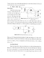
Example 1: Three 60.35 mm (2.376 in.) Diam Cylinder Bores.
Figure 7 shows a brake housing, cast from AZ92A magnesium alloy, in which the walls of three 60.35 mm (2.376 in.)
diam cylinder bores were roller burnished to a diametral tolerance of ±0.020 mm (±0.0008 in.) and a 0.38 m (15 in.)
surface finish. These bores had been machined undersize to a diametral tolerance of 0.025 to 0.038 mm (0.001 to 0.0015
in.) and a 1.50 m (60 in.) surface finish.
Speed 435 rev/min (82 m/min, or 270 sfm)
Feed
2.5 mm/rev (0.100 in./rev)
Cutting fluid
SAE 20 oil:kerosene (1:1)
Downtime for changing tools
12 min
Average tool life
10,000 bores
Fig. 7 Roller burnishing cylindrical bores in a magnesium brake housing
For roller burnishing, the housing was clamped, bore side up, to the fixture base with L-type clamps, as shown in Fig. 7.
The burnishing tool contained a series of hardened tapered rollers that rode on a mandrel tapered inversely to the taper of
the rollers.
Fillet Rolling
Fillet rolling is done to improve fatigue resistance. It is a specialized operation that uses a narrow roller of required shape.
The rolling and pressing cause combined rolling and sliding (lubrication is used). Forces are not large; for example, a
fillet of 0.8 mm ( in.) radius can usually be rolled with a force of 440 N (100 lbf) or less in ten revolutions (passes)
around the fillet. A plain roller of oil-hardening tool steel at 62 to 65 HRC can roll fillets on several thousand pieces at
low cost.
Bearingizing
In a modification of roller burnishing known as bearingizing, metal surfaces are finished by a combined rolling and
peening action. In this process, hardened rollers rotating around and bearing on cams (Fig. 8) rise and fall rapidly,
delivering as many as 200,000 blows per minute. This action produces a smooth surface, improves roundness and
straightness, and increases surface hardness to a depth of 0.13 to 0.38 mm (0.005 to 0.015 in.). The inside surfaces of
tubes 3 to 6 m (10 to 20 ft) long have been successfully processed by this method. In most applications, however, bore
length is relatively short (less than three times diameter). Copper alloys, because of their low hardness and high ductility,
are especially suitable for this process.
Fig. 8 Cross sections of bearingizing tools positioned in workpieces showing rollers riding over cams
Tools. Three basic types of tools for the finishing of bores are illustrated in Fig. 9. Selection depends on whether the hole
is through or blind and, for blind holes, on how close to the bottom that finishing is required. The bottoming tool shown
in Fig. 9 can finish to 0.76 mm (0.030 in.) from the bottom of a blind hole. Two styles of cams are also available (Fig. 8);
the steep-rise cam is used in thin-wall parts.
Fig. 9 Bearingizing tools for finishing through and blind holes. (a) Bottoming. (b) Semibottoming. (c) Through-
hole
Taper-shank tools are available from stock in diameters of 4.8 to 25 mm ( to 1 in.) in 0.8 mm ( in.) increments.
Overall length and working length (distance from the leading end of the tool to the beginning of the taper shank) vary
proportionately, from 75 mm (2 in.) for the 4.8 mm ( in.) diam tool to 152 mm (6 in.) for the 25 mm (1 in.) diam
tool. The number and size of rollers also vary with diameter; for example, the 4.8 mm ( in.) diam tool has 6 rollers,
while the 25 mm (1 in.) diam tool has 12.
Tools are available in diameters up to 305 mm (12 in.), but sizes larger than 203 mm (8 in.) in diameter are seldom used.
A tool can be adjusted in a total range of about 0.10 mm (0.004 in.) by changing rollers. Rollers are available in
increments of 0.0025 mm (0.0001 in.). Because the rollers are diametrically opposed, the tool can be adjusted in
increments of 0.0051 mm (0.0002 in.).
Tolerance and Finish. Bores are commonly finished to tolerances of ±0.0001 mm/mm (±0.0001 in./in.) of diameter by
the bearingizing process. Notable examples are piston-pin bores, which are finished to a total tolerance of 0.0051 mm
(0.0002 in.). However, such parts must be finished to close tolerances in a prior operation, because the total expansion for
holes less than 25 mm (1 in.) in diameter is only about 0.013 mm (0.0005 in.) (except holes in thin-wall tubing, which can
be expanded several hundredths of a millimeter). For holes larger than 25 mm (1 in.) in diameter, a total expansion of
0.025 mm (0.001 in.) is normal. Hole straightness depends largely on prior operations.
The preferred prior surface is one produced by a single-point tool (as in boring) to a roughness of 2.00 to 3.00 m (80 to
120 in.). Starting with this roughness, most metals can be finished to about 0.125 m (5 in.). For porous metals (such
as sintered bronze), however, the resulting finish is likely to be closer to 0.30 m (12 in.).
Speed and Feed. Neither speed nor feed is critical. Speeds of 90 to 150 m/min (300 to 500 sfm) have proved
satisfactory. Because the operation is done in one quick pass, feed rate is difficult to measure, but 3800 to 6350 mm/min
(150 to 250 in./min) is normal.
Little time is required per hole; for example, a hole 75 mm (3 in.) deep is finished in slightly over 1 s. Indexing of the
workpiece usually requires more time than the actual operation.
Lubrication is seldom necessary, but tools should be cleaned frequently with a light oil having a viscosity of about 100
SUS (Saybolt universal second). Spindle oil is often used. Only a few drops applied with a squirt can or a brush are
necessary to get oil into the roller cage. Centrifugal force then washes out metal particles or dust.
Tapping
Revised by Mark Johnson, Tapmatic Corporation
Introduction
TAPPING is a machining process for producing internal threads. A tap is a cylindrical or conical thread-cutting tool
having threads of a desired form on the periphery. Combining rotary motion with axial motion, the tap cuts or forms the
internal thread.
Most metals that can be machined with single-point tools can be tapped, but the cost of tapping usually rises sharply as
the hardness of the work metal increases beyond 25 HRC. Although steel as hard as 52 HRC can be tapped, efficiency is
low and cost is high.
Threads as fine as 360 threads per 25 mm (1 in.) in 0.335 mm (0.0132 in.) diam holes or as coarse as 3 threads per 25 mm
(1 in.) in 610 mm (24 in.) diam pipe fittings are routinely tapped.
Machines and Accessories
The machines most commonly used for tapping are drill presses, tapping machines, gang machines, manual or automatic
turret lathes, and other multiple-operation machines. Tapping machines are basically drill presses equipped with lead
screws, tap holders, and reversing mechanisms.
Lead screws or lead-control devices provide a means of regulating the desired feed rate during tapping. The amount of
feed per revolution determines the pitch of the tapped thread. Lead screws convert rotary motion into linear motion so that
the axial motion of the tap into the hole conforms with the desired pitch of the thread. Lead-screw control is often used in
high-volume applications or with larger tap sizes to ensure quality threads.
A typical lead control is shown in Fig. 1. A driving pinion, keyed to the main drive shaft, drives a gear keyed to the lead-
screw shaft. The lead screw passes through the lead-screw nut, which is fastened to the stationary housing. When the
main drive shaft rotates, it turns the lead-screw shaft. The rotation of the lead screw within the lead-screw nut causes the
assembly to travel up or down at a speed regulated by the lead screw. This controlled action, transmitted to the chuck,
drives the tap into the workpiece at a controlled rate. At the end of the stroke, when the tap has penetrated the workpiece
to the desired depth, the direction of shaft rotation is reversed, and the lead-control mechanism backs the tap out of the
tapped hole.
Fig. 1 Lead-screw mechanism for control of top feed. See text for discussion.
There are two disadvantages of lead control in tapping. First, the need to return to the starting point to begin each cycle,
and to stop rotation between cycles, may lengthen the tapping cycle. For example, when using a collapsible tap, it would
be possible to retract the tap more rapidly from the workpiece without lead control. Second, changing taps for different
thread sizes consumes more time when lead control is used because the feed-controlling members in the mechanism also
must be changed. The additional time required may increase cost in short-run tapping, in which the thread pitch is
frequently changed.
Tension/compression tapping spindles and attachments provide axial float and compensate for any difference
between machine feed and correct tap feed. The axial float of tapping attachments with tension/compression mechanisms
also makes it possible to tap several different thread pitches at the same time with a single machine feed rate.
Self-reversing tapping attachments eliminate the need for reversing motors for tap retraction and provide
precision tapping for machines without reversing motors. These attachments can be used on all machines that provide
rotation to the reversing mechanism inside the attachment.
Compact reversing attachments are the most popular type of self-reversing tapping attachment. These devices have a self-
feed, or axial float, that permits the tap to act as its own lead screw, and their compact size provides versatility. Other
types of self-reversing attachments utilize built-in lead screws or require a higher degree of operator skill in maintaining
proper feed rates.
Ball drive provides a reduction in friction during tapping operations. A spring-biased rolling ball transmits rotational
power to the tap and compensates for any operator or machine feed error during tapping. The symmetrical design of ball-
driven tools has made it possible to tap right- or left-hand threads with a self-reversing tool.
Nonreversing tapping attachments must be used on machines equipped with reversing motors. These devices are
extensively used on radial drills, milling machines, lathes, and numerical-controlled equipment. The main advantages of
nonreversing attachments are their simplicity and compact design.
Drill Presses. When no other machining operations are involved, drill presses are often used for tapping because they
are easy to set up and simple to operate. Drill presses can be provided with lead-control devices to regulate tap feed rates.
However, when lead control is required, tapping machines are ordinarily used rather than drill presses.
When a solid tap is used, the drill press must be provided with a tapping attachment or a reversing motor having a
tension/compression tap holder. This additional equipment is necessary because the spindle cannot be stopped quickly or
precisely enough to hold specified depth tolerance and is not easily reversed to allow the tap to be removed from the
workpiece. With a tapping attachment, movement of the feeding lever is stopped at a predetermined point; the tapping
attachment then automatically stops the rotation of the tap. Upward movement of the control lever causes the tapping
attachment to reverse and spin the tap out of the hole.
With a collapsible tap, a tapping attachment is not required. The tap penetrates the work to a predetermined point at which
it automatically collapses and retracts from the work, letting the spindle return without stopping or reversing.
Single-spindle tapping machines are generally used for small-to-medium production lots. The simpler models have
no lead control but depend on the screw action of the tap in the hole to govern feed.
In a hydraulically driven machine without lead control, axially floated spindles or holders compensate for differences
between the feed of the machine and the lead of the tap. An uncontrolled hydraulic feed will not maintain a stable feed
rate and might tear the threads.
Multiple-spindle tapping machines are for high-volume production. All spindles (some machines have 25 or more)
are rotated by a common power source. With these machines, holes of different sizes can be tapped simultaneously.
Spindles having axial float can compensate for differences between the lead of the tap and the feed of the spindle. Thus,
different thread pitches can be tapped simultaneously in the same machine.
Gang machines permit in-line drilling, reaming, and tapping operations, much as in multiple-spindle drilling. Gang
machines are intended and used primarily for low production.
Manual turret lathes are used for tapping small production lots. Turret lathes are generally more accurate than
machines that rotate the tap instead of the workpiece. Moreover, in a turret lathe, tapping can be combined with other
operations; therefore, on the same machine the holes can be drilled, bored, reamed, and tapped. This permits the use of
higher tapping speed and results in longer tap life than is possible when the holes are less accurate. A lead-control device
is almost mandatory when tapping on a turret lathe because the mass of the turret decreases the feel the operator needs to
control the feed by hand.
Automatic Turret Lathes and Bar or Chucking Machines. Tapping can often be included in a sequence of
operations in an automatic turret lathe or in a single-spindle or multiple-spindle bar or chucking machine. However,
because of the relatively long setup time required for these machines, they are usually efficient only for large production
lots. Moreover, tapping efficiency may depend on the number of other operations that can be incorporated into the
automatic sequence; some machines can perform 25 operations per piece. All automatic turret lathes, bar machines, and
chucking machines use lead-control devices for regulating the feed.
Machine Selection. Selection of the appropriate machine for a tapping operation is based on:
• Size of the workpiece
• Shape of the workpiece
• Production quantity
• Tolerance
• Specified finish
• Number of related operations
• Cost
Many machines tap a wide range of thread sizes. Somewhere within its range, however, a machine is most effective in
producing quality threads. Small-diameter, fine-pitch threads should be cut on machines of relatively low power, while
larger threads and harder materials require heavier machines with more power. Pipe threads require considerably more
torque than straight threads.
Tap Classification
On the basis of their construction, taps are classified into seven categories:
• Solid taps
• Shell taps
• Sectional taps
• Expansion taps
• Inserted-chaser taps
• Adjustable taps
• Collapsible taps
The following sections describe the design and function of taps in these categories.
Solid Taps
Solid taps are one-piece taps, usually made of high-speed steel but sometimes of carbon tool steel or of carbide. Solid taps
are of two basic types: straight thread and taper thread. Straight-thread taps make threads that do not vary in pitch
diameter; taper-thread taps make threads with a uniform reduction in pitch diameter from thread to thread (pipe threads).
Standard nomenclature for details of solid taps is given in Fig. 2. Most solid taps have flutes and chamfer.
Fig. 2 Standard nomenclature for design details of solid taps
Flutes. Taps have flutes for three reasons: to provide cutting edges, to provide chip clearance and a means of chip
control, and to conduct fluid to the cutting sections of the tap. Taps may have straight flutes, spiral flutes, or a
combination of both. Taps with straight flutes are the most commonly used because they are more easily made and
sharpened than spiral-flute taps and because they perform satisfactorily under many conditions.
Chamfer. Solid taps have three types of chamfer:
• Taper chamfer (7 to 9 threads)
• Plug chamfer (3 to 5 threads)
• Bottoming chamfer (1 to 1 threads)
Taper chamfer (Fig. 3a) distributes the cutting load over the greatest number of threads and permits easiest starting of
the tap into the workpiece. Therefore, taper-chamfer taps are especially suited for tapping difficult-to-machine metals.
However, taper-chamfer taps are seldom suitable for blind holes (too much of the hole is left unthreaded). They also
require longer travel than other types to produce full threads in through holes.
Fig. 3 Chamfers for solid taps
Plug chamfer (Fig. 3b) is the most commonly used type. Taps with plug chamfer are not required to penetrate a hole as
deeply as taps with taper chamfer to produce a given length of thread; therefore, they produce at a slightly higher rate.
Except in the difficult-to-machine metals, a plug-chamfer tap enters the hole with reasonable ease. If sufficient clearance
can be provided, plug-chamfer taps are used successfully in blind-hole tapping.
Bottoming chamfer (Fig. 3c) is usually used only for blind holes. When tapping a blind hole in a difficult-to-machine
metal, it is common practice to tap as deeply as possible with a taper-chamfer tap or plug-chamfer tap (or sometimes with
both, successively) and then to use a bottoming-chamfer tap to finish tapping to the required depth. This practice reduces
the time that the 1 to 1 cutting threads in a bottoming chamfer are under maximum stress.
Basic Styles of Solid Taps. The solid taps generally in use are standard hand taps, spiral-point taps, and spiral-flute
taps. Each style is described below.
Hand taps (Fig. 4a) are the most common type. They were originally used for tapping by hand, and although most are
now used in machines, the name has persisted.
Fig. 4 Three basic styles of solid taps
Hand taps are produced with either straight or spiral flutes. Many have four flutes, but for tapping metals that produce
soft, stringy chips or for ease of chip removal in deep-hole tapping, three or even two flutes can be used.
Spiral-point taps (Fig. 4b) have straight flutes supplemented by left-hand angular flutes near the point. The purpose of
the spiral point is to push the chips ahead of the tap as tapping progresses.
Spiral-point taps are best suited for through holes. However, spiral-point taps with plug chamfer can be used for blind
holes, provided there is enough clearance beyond the tapped section to accommodate the chips.
Because the flutes in spiral-point taps are less needed for chip passage, they can be shallower than in standard hand taps,
and the tap body can have a stronger cross section. The angular cutting edges generated by the spiral points cut with a
shearing action, producing a fine finish on the threads. Furthermore, with the flutes clear of chips, the cutting fluid can
move more freely along the flutes to the cutting edges.
Spiral-flute taps (Fig. 4c) can have right-hand or left-hand flutes; right-hand flutes are more common. The spiral
produces a lifting action that forces the chips along the flute. The spiral of the flutes may be regular (about 25 to 35°) or
fast (about 50 to 65°); a fast spiral accelerates chip removal.
Spiral-flute taps are also used to advantage when tapping holes having keyways or other interruptions. The cutting edges
meet the interruption progressively, thus cutting more smoothly and being less subject to shock.
Taps cutting regular right-hand threads can be furnished with left-hand spirals. These spirals will push the chips ahead of
the tap through the hole for disposal. Keeping the chips out of the flutes minimizes tap breakage and thread damage when
the tap is reversed for removal. The shearing action resulting from the angle of the cutting edge on spiral-flute taps
produces a better thread finish on difficult-to-machine metals.
Modified Styles of Solid Taps. Six of the many modifications of the three basic styles of solid taps are shown in Fig.
5.
Fig. 5 Six modifications of solid taps
Bent-shank tapper taps (Fig. 5a) are used for tapping nuts in an automatic tapping machine. The nuts are usually fed
from a hopper, and as they are tapped, they pass over the shank and are ejected automatically over the bent end.
Consequently, it is unnecessary to reverse the tap as it would be with a conventional tap.
Combination roughing-and finishing taps (Fig. 5b) have two stages; the first cuts to rough dimensions, and the
second cuts the finished thread. The main disadvantage of these taps is the distance they extend beyond the workpiece at
the completion of tapping; this limits their use to the tapping of through holes.
Step taps (Fig. 5c) are used for simultaneously cutting threads of the same pitch but of two different diameters.
Short-flute spiral-point taps (Fig. 5d) are designed for through holes in thin sections such as webs and sheet metal.
Because they are fluted only at the spiral point, these taps are durable. They are limited to tapped holes that are not deeper
than one diameter.
Pulley taps (Fig. 5e) have the same thread dimensions as hand taps, but they have shanks as large in diameter as the
major diameter of the tap thread and much longer than the shanks of hand taps. When the taps thread holes for oil cups or
setscrews in pulley hubs, the oversize shanks act as guides in the access holes in the pulley rims to keep the taps aligned.
Piloted ground-thread taps (Fig. 5f) are used to maintain the concentricity of threads in workpiece holes. The pilot
can be guided by the work hole, a special pilot hole, or a bushing. Piloted taps are specially made to order.
Sizing Solid Taps. With solid taps, the relationship between tap size and solid hole size is varied to meet specific
conditions. For example, a tapped hole in a part to be electroplated must be oversize by a minimum of four times plate
thickness to compensate for the electrodeposited metal. Another condition for which compensation is required is the
outward force exerted by the tap when cutting. This force, particularly in thin-wall parts, may be sufficient to influence
the final results because the part will expand during tapping and will contract when the tap is removed. To meet these
conditions, standard taps are ground oversize in established increments and then coded for identification, as indicated in
Table 1.
Table 1 Tolerance on pitch diameter of standard taps ground oversize
Code
(a)
Tolerance
Taps 25 mm (1 in.) or less in diameter
GH1, mm (in.)
Basic, to basic plus 0.0125 (0.0005)
GH2, mm (in.)
Basic plus 0.0125-0.025 (0.0005-0.001)
GH3, mm (in.)
Basic plus 0.025-0.0375 (0.001-0.0015)
GH4, mm (in.)
Basic plus 0.0375-0.05 (0.0015-0.002)
GH5, mm (in.)
Basic plus 0.05-0.0635 (0.002-0.0025)
GH6, mm (in.)
Basic plus 0.0635-0.075 (0.0025-0.003)
GH7
(b)
, mm (in.)
Basic plus 0.075-0.087 (0.003-0.0035)
Taps over 25 mm (1 in.), and through 38 mm (1 in.) in diameter
GH2, mm (in.)
Basic, to basic plus 0.025 (0.001)
GH4, mm (in.)
Basic plus 0.025-0.05 (0.001-0.002)
GH6, mm (in.)
Basic plus 0.05-0.075 (0.002-0.003)
GH8, mm (in.)
Basic plus 0.075-0.10 (0.003-0.004)
(a)
GH, Ground high (oversize).
(b)
Nonstandard; for tapping workpieces that are susceptible to extreme
distortion or to which extremely heavy electrodeposits will be applied.
Some manufacturers stock GH7 taps in a special series for tapping
zinc die castings.
Standard taps ground undersize, identified as GL (ground low), are also available. These taps are used when the tapped
hole will be retapped after some process such as heat treating has caused distortion. They are also used when the mating
part is undersize. Tolerances for three GL taps are:
Code
Tolerance
GL1
Basic, to basic minus 0.0125 mm (0.0005 in.)
GL2
Basic minus 0.0125-0.025 mm (0.0005-0.0010 in.)
GL3
Basic minus 0.025-0.0375 mm (0.0010-0.0015 in.)
Shell and Sectional Taps
Shell taps are generally made of high-speed steel, without shanks, and are threaded to, or nearly to, their full length. As
shown in Fig. 6(a), this type of tap has a full-length hole to accommodate an arbor or shank for driving purposes. The
arbor hole is often made with a keyway for a positive drive. Other shell taps may have a tongue or groove across the
middle of the back of the tap to fit a specific driver or shank.
Fig. 6 Two styles of taps used with inserted shanks
Shell taps are made to order, usually 25 mm (1 in.) or larger in diameter and 13 mm ( in.) or more in length. These taps
are best suited to large-diameter holes where thread pitch is eight to the inch or finer and where a short tap is required.
Shell taps can be resharpened in a gang by placing two or more on an arbor. In the large diameters, they are sometimes
cheaper than solid taps. However, shell taps of the smaller diameters are generally more expensive than their solid tap
counterparts.
Sectional taps (Fig. 6b) are similar to shell taps in that they have inserted shanks. The cutting section is generally shorter
for sectional taps than for shell taps. Like shell taps, they can be resharpened in gang, with two or more on an arbor.
Expansion Taps
Of the various kinds of expansion taps available on special order, all have two features in common:
• An axial hole is drilled from the front end to beyond the thread length of the tap
•
One or more radial slots or saw cuts are made from the surface of the tap to this hole between pairs of
flutes. The slots, which exte
nd the full working length of the tap, provide springiness to the threaded
portion
Two types of expansion taps are illustrated in Fig. 7.
Fig. 7 Two styles of expansion taps
These taps are available in sizes 9.5 mm ( in.) in diameter and larger. They are ordinarily used only for finishing work
or for tapping free-machining metals. They are comparatively high in cost.
Inserted-Chaser Taps
The body of an inserted-chaser tap has slots that accept sets of four or more chasers held in place either by wedges,
screws, and grooves, or by a combination of screws and serrations cut into the chaser body. A typical fixed-chaser type is
shown in Fig. 8.
Fig. 8 Typical inserted-chaser tap
In one common inserted-chaser type, each chaser is wedge shaped (wider at the base than at the cutting surface). The ends
of the chasers stop against a shoulder on the body of the tap and are held securely in position by hardened and ground
wedges (Fig. 9). These taps, with a cut thread, are standard with some tap manufacturers and are available in sizes ranging
from 38 to 150 mm (1 to 6 in.) in diameter. The initial cost is relatively high, but for long production runs the
replacement cost of a set of chasers is considerably lower than that of a solid tap. Ground-thread chasers for tapping taper
pipe threads are also available, but are special and designed to fit the user's tap bodies. Oversize holes can be tapped with
inserted-chaser pipe taps by placing shims of uniform thickness under the bases of the blades.
Fig. 9 Inserted-chaser tap in which chasers are held in place by wedges
Adjustable Taps. Another type of inserted-chaser tap is adjustable; that is, it can be made to cut smaller or larger. This
tap uses ground-thread chasers with serrations on the backs. The chasers are held in position by locking cams, two for
each chaser. The backs of the chasers stop against two hardened and ground nuts on the tap body. The taps are adjusted
by loosening the locking cams and turning the nut nearer the chaser. The other nut locks the adjusting nut. The tap will
cut larger when the chasers are pushed forward. A still larger cut can be made by removing the chasers from the body and
replacing them one serration farther away from the axis of the tap. A smaller cut is made by placing the chasers one
serration closer to the axis of the tap.
These taps are used almost exclusively as finishing taps where extreme accuracy is required. They are made only on
special order, and the cost is relatively high.
Collapsible Taps
A collapsible tap has chasers that are set to retract radially after the thread is cut, so that the tap can be withdrawn without
reverse rotation. There are two basic types of collapsible taps: rotary and stationary. Rotary taps are used in machines in
which the tool rotates, such as drill presses and tapping machines. Stationary taps are used in machines that rotate the
workpiece, such as turret lathes. Both types are controlled by a yoke or ring arrangement that automatically withdraws the
cutting edges when pressure is applied to the yoke. Stationary collapsible taps (Fig. 10) have a hand lever to reset the tap.
Collapsible taps can be used in the same equipment as solid taps, provided there is enough room to accommodate the
collapsing head.
Fig. 10 Stationary (nonrotating) collapsible tap
Collapsible taps are generally designed with flat or blade-type chasers, but for tapping large diameters, taps with circular
chasers are frequently used. With a demountable nosepiece and blocks, either blade or circular chasers can be used in the
same collapsible tap.
Taps with blade chasers are generally made for diameters of 30 to 100 mm (1 to 4 in.). Circular-chaser taps are made
for 90 to 130 mm (3 to 5 in.) diameters.
Advantages. Collapsible taps have two advantages over solid taps: They can be adjusted, and they can be removed
from the workpiece without reversing the spindle. The adjustability of collapsible taps is advantageous on first-run jobs in
which the reaction to the tapping forces is unknown, because it permits variation in the amount of compensation for
distortion of the metal being tapped. Collapsible taps can also be adjusted to allow for electroplated finishes or for growth
resulting from heat treatment. Therefore, collapsible taps are adaptable to both short runs and high production.
Collapsing the tap eliminates the wear that would be caused by friction between the cut threads and the tap when the tap
is reversed for removal. In addition, a collapsible tap minimizes the danger of tap breakage or thread damage caused by
trapped chips as the tap is removed from the tapped hole. This is of particular benefit when tapping metals that make
stringy chips.
Disadvantages. Compared to solid taps, collapsible taps have four disadvantages:
• Because of the greater overhung inertia of a collapsible tap, a sturdier mach
ine is required than for a
solid tap
•
Because collapsible taps have a number of moving parts, they require more maintenance; worn or loose
components cause excessive variation in tapped holes
• They can seldom be used for holes smaller than 30 mm (1 in.) in diameter
• Collapsible taps are expensive
Tap Materials
Most taps are made of high-speed steel. Carbide blades (chasers) are sometimes used in adjustable or inserted-chaser taps.
However, the use of carbide is largely restricted to special applications for example, the tapping of especially abrasive
grades of cast iron or abrasive nonmetals such as fiberglass and filled plastics.
General-purpose high-speed steels, such as M1, M2, M7, and M10, are most widely used for taps and have proved
satisfactory for most applications. For tapping difficult-to-machine metals (such as heat-resistant alloys, or steels harder
than about 35 HRC), taps made of one of the more highly alloyed high-speed steels, such as M15 or T15, are often
justified. However, taps made of the more highly alloyed high-speed steels cost two to three times as much as similar taps
made of the general-purpose types; the more highly alloyed types are more difficult to grind and are more susceptible to
grinding burn.
For special tap designs that require greater resistance to abrasion, type M3 (class 2) or type M4 is generally used. Where
requirements include high abrasion resistance and/or very high resistance to softening at elevated temperatures, types T15
and M42 are typically used.
Cost. To the user, tap cost and tap expendability are directly related, especially in smaller sizes. Most users will sacrifice
tap life rather than pay for maintenance and repair. A tap chipped along its chamfer or in the leading threads can be
salvaged, but replacement may be more economical. In addition, cheaper taps, which are discarded after short runs, may
be more economical than costly taps with a longer production life, depending on the cost of downtime for changing taps.
In multiple-spindle setups in which tap operating conditions are poor, a sacrifice in tap life may prove less expensive than
a second tapping operation.
Surface Treatment of Taps
Many taps are given one of the following surface treatments: nitriding, titanium nitride coatings, chromium plating, or
oxidation (black oxide) by steam. Titanium nitride coatings are the most common treatments used in production shops.
These treatments increase tap life and improve thread finish by:
• Reducing adherence of the tap to the work metal
• Reducing chip buildup on cutting edges
• Minimizing wear caused by erosion from chips
Surface treatments can increase tap life by 500% or more. The greatest benefit of surface treatment is realized in metals
that form stringy chips or in hard metals such as heat-treated steel. The relative merits of the three types of treatment are
debatable; all have proved helpful. However, steam-treated taps are not recommended for use in soft metals such as brass,
because they are likely to tap oversize.
The main disadvantages of surface treatments are cost and inconvenience. Regardless of the treatment used, the
penetration (or buildup, in the case of plating) is so small that the taps must be re-treated each time they are ground. This
is sometimes a great inconvenience, especially when the taps must be sent out for treatment.
Selection of Tap Features
The main influences on the selection of tap design features are work metal composition and hardness, class of thread
required, and cost. The following example describes an application in which changes in the design of the tap proved
beneficial.
Example 1: Tap Redesign to Produce Acceptable Threads.
The tapping of 1-14 UNS threads in free-cutting brass was one of a sequence of operations in a multiple-spindle machine.
The taps originally used were standard four-flute taps with a 12° positive rake and relatively wide lands, and they had
been subjected to a steam oxide surface treatment. These taps failed to pick up the lead; consequently, the threads were
reamed to the extent that a no-go gage would enter the full length of the threads. In addition, the steam oxide treatment
caused the taps to cut oversize because the pitted surface from the oxide treatment, combined with the use of soluble oil
as a cutting fluid, caused the thread flanks to load.
The following revisions were made:
• The land width of the tap was reduced from 7.6 to 4.2 mm (0.300 to 0.165 in.)
• The rake was reduced to 3°
• The surface treatment of the taps was changed to nitriding
• A light mineral oil (paraffin base) was substituted for the soluble oil
These changes produced acceptable parts. Tap life between grinds was 32,000 pieces. Each tap could be reground three
times; therefore, total tap life averaged 128,000 pieces.
Flute Selection. Selecting between three-flute and four-flute taps often involves a difficult decision. Four-flute taps
have less cutting load per tooth, but three-flute taps in the same size have greater strength and more chip room. Thread
pitch sometimes influences the decision, as indicated in the following example.
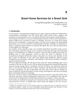
Example 2: Three-Flute Versus Four-Flute Taps.
A four-flute spiral-point tap proved superior to one with three flutes for cutting -16 UNF-2B threads in steel nuts, using
an automatic nut tapper (Fig. 11). The greater number of cutting edges on the four-flute tap, together with the smaller
chips it produced, resulted in smoother finish on the threads and longer tap life. Tap details and operating conditions are
given with Fig. 11. However, for tapping -10 UNC-2B threads in these nuts, a three-flute tap was preferred because of
the greater strength in the tap and increased clearance to pass the larger chips.
Tap details
Material
M1 high-speed steel
Surface treatment
Steam oxide
Hook angle, degrees
8
Number of chamfered threads
6
Chamfer angle
5° 40'
Chamfer relief, mm (in.)
0.23-0.028 (0.009-0.0011)
Spiral-point angle
7° 45'
Spiral-point length
8 threads
Operating conditions
Speed, at 407 rev/min, m/min (sfm)
24 (80)
Cutting fluid
Sulfurized oil
Thread length, mm (in.)
19 ( ) (through)
Percentage of thread
71%
Tap life per grind, pieces
10,000
Production rate, pieces/h
500
Fig. 11 Use of a four-flute spiral-point tap for threading nuts in an automatic nut tapper. A three-
flute tap was
preferred for -10 UNC-2B threads in these nuts.
Factors That Influence Procedures and Results
The principal factors that influence the selection of equipment and procedure for tapping and that affect thread quality,
productivity, and cost are:
• Composition and hardness of the metal being tapped
• Size and shape of the workpiece
• Thread size and depth
• Tolerance and finish specified
• Whether blind or through holes are being tapped
• Speed
• Use or nonuse of lead control
• Cutting fluid
The following sections discuss the influence and control of these variables (except for lead control, which is discussed in
the section "Machines and Accessories" in this article).
Metal Composition and Hardness
A metal is seldom selected for its machinability alone. However, a change of material may increase productivity and
decrease cost without sacrificing the required properties. The simplest change is that from a specific alloy to a free-
machining counterpart. Invariably, the tapping of free-machining grades results in more accurate threads of better finish at
higher production rates and lower cost than the tapping of nonfree-machining grades that are otherwise similar in
composition and hardness.
Except for low-carbon steels that do not contain free-cutting additives, as well as certain other soft metals that form
gummy, adherent chips in machining, hard metals are less readily tapped than soft metals. Figure 12 illustrates the usual
effect of differences in work metal hardness on the tapping of carbon and low-alloy steels. In this test on the tapping of
-28 and -20 through holes in similar low-alloy steels with M10 high-speed steel tools, the cost for tapping at a hardness
of 52 HRC was about 30 times that at 15 HRC; for tapping at a hardness of 47 HRC, about 6 times.
Tapping conditions (holes of both diameters)
Type of machine
Automatic tapping
Depth of through holes, mm (in.)
32 (1 )
Tap drill for -28, mm (in.)
No. 3, 5.41 (0.213)
Tap drill for -20, mm (in.)
11.5 ( )
Cutting fluid
Lithopone-pigmented wax and fatty ester in lard-mineral oil
Tap material
M10 high-speed steel
-28 -20
Tap details
15 HRC
47, 52 HRC
15 HRC
47, 52 HRC
Flute helix angle, degrees
0 0 0 0
Hook angle, degrees
2 5 2 5
Chamfer angle, degrees
30 42 30 42
Chamfer relief angles, degrees
5 5 5 5
Number of lead threads
3 3 4 4
Fig. 12 Effect of hardness on the tapping of carbon and low-alloy steel. (a) -28 UNF through holes. (b) -
20
UNF through holes
Under the conditions of this test, tap life increased with an increase in hole diameter on the basis of volume of metal
removed, but decreased on the basis of number of holes per grind. Tapping cost for the 6.4 mm ( in.) diam holes was
three times that for the 13 mm ( in.) diam holes on the basis of volume of metal removed, but was only slightly greater
on a per-hole basis. Machining and tool details are given in Fig. 12.
A tap manufacturer conducted a series of tests on 11 steels that ranged in hardness from 5 to 55 HRC to determine the
effect of hardness on tapping. Data obtained in these tests were used as the basis for the recommendations given in Table
2.
Table 2 Recommended practice for tapping steels in three ranges of hardness
Hardness of steel tapped, HRC Process variable
5-30 30-40 40-55
Tap design
Standard Modified standard, or special
(a)
Special
(a)
Tap material
(b)
T1, M1, M7, M10
M2, M3 T15, M3, M33, M42
Tap hardness, minimum
62 HRC 64 HRC 66 HRC
Surface treatment of tap
Steam oxide
(c)
Nitride plus steam oxide Nitride plus steam oxide
Percentage of full thread
75% 60% 55%
Speed, m/min (sfm)
30 max (100 max)
6-14 (20-45)
0.15-3.0 ( -10)
(a)
Special tap should have four flutes, 3° (positive) hook angle, thread relief, and 3 to 4
thread chamfer.
(b)
High-speed steels similar in total alloy content to steels listed can be substituted.
(c)
Or other oxidizing process; see the section "Surface Treatment of Taps" in this article.
As indicated in Table 2, taps made of general-purpose high-speed steels are usually the most economical when the
hardness of the metal being tapped does not exceed 30 or 32 HRC; as workpiece hardness increases above this level, one
of the more highly alloyed high-speed steels is usually selected. Table 2 also indicates that tap design is more critical
when high-hardness steels are being tapped.
A difference in work metal composition can affect requirements for hole preparation before tapping. For example, when
tapping aluminum, accuracy and thread finish can usually be improved by reaming after drilling, but in tapping carbon,
alloy, or stainless steel, reaming is seldom needed.
Workpiece Size and Shape
The size and shape of the workpiece must be considered in establishing tapping procedures. Tapping problems are more
likely to be encountered with workpieces that are too weak or flimsy to withstand normal tapping forces. This inability
can result in a loss of dimensional control or even in damage to the workpiece. The example that follows describes
procedures that have been successful for tapping tubular workpieces with a wall 6.0 mm ( in.) thick.
Example 3: Tapping Seam-Welded Tubing.
An eight-station vertical tapping machine and six-flute solid taps were used for cutting 2-11 NPSC threads through 54
mm (2 in.) lengths of seam-welded 1020 steel tubing (wall thickness: 6.0 mm, or in.) for use as steam-pipe
couplings. As shown in Fig. 13, the workpieces were held in air chucks. After each piece had been tapped, it was
automatically pushed up the long shank of the tap by the next piece, until the shank was filled, at which time the
workpieces were unloaded. The eight stations were synchronized to permit one-man operation.
Tap details
Material
M1 high-speed steel
Number of flutes
6
Overall length, mm (in.)
380 (15)
Chamfer length, mm (in.)
27.4 (1 )
Chamfer angles (double)
10° 15' and 4° 36'
Operating conditions
Speed, at 80 rev/min, m/min (sfm)
15 (50)
Cutting fluid
Sulfurized oil
Tap life per grind, pieces
1200
Production rate, pieces/h
80
Workpiece hardness, HRB
75-80
Fig. 13 Tapping of seam-welded couplings
Solid taps were used in preference to collapsible taps because the variation from true roundness of the inside diameter,
together with the seam, required that the tap provide some reaming action in addition to cutting the threads. Tap details
and operating conditions are included in Fig. 13.
Size, Pitch, and Percentage of Thread
Thread size and pitch and the percentage of full depth to which the threads are cut determine the metal removed in any
tapping operation and have a large effect on efficiency and tap life. As the size of thread increases, the amount of metal
removed increases in approximate proportion to the hole diameter (assuming that other factors remain constant). As the
thread becomes coarser, the amount of metal removed in tapping increases for any thread diameter and percentage of
thread.
Percentage of thread is half the difference between the basic major diameter and the actual minor diameter of an internal
thread, divided by the basic thread height and expressed in percent. As the percentage of thread increases, the amount of
metal removed will increase for any thread pitch and size.
Example 4: Effect of Increase in Percentage of Thread on Speed, Production Rate, and
Tap Life.
Two-flute spiral-point taps with a 15° chamfer were used in a two-spindle tapping machine for cutting 8-36 UNF-2B
threads in through holes in low-carbon steel plate 2.84 mm (0.112 in.) thick. Speed, production rate, and tap life for
tapping these holes to 55 and 78% of full thread depth were as follows:
Percentage of
full thread depth
55 78
Speed, rev/min
1863 1398
Speed, m/min (sfm)
24 (80)
18 (60)
Holes tapped per hour
2195 1925
Accuracy and Finish
Conditions that cause dimensional variation in tapped threads also cause rough finish on the threads. Among these
conditions are lack of concentricity between the tap holder and the spindle, worn taps, entrapment of chips in the tapped
hole, and chip buildup on cutting edges and flanks of the threads.
Concentricity of Holder and Spindle. New taps are seldom responsible for poor threads. However, even a new tap
is no more accurate than the combined eccentricity of the holder and rotating spindle. The eccentricity of these rotating
members will cause the tapped holes to be oversize.
Condition of Taps. Worn taps are a major source of dimensional variation in tapped holes or of poor finish on threads
or both. As the cutting edges of a tap become dull, the chips produced are torn, rather than cut or shaved. Improperly
sharpened taps, or taps with the wrong cutting-edge angles, will have a similar adverse effect on thread finish.
Chip Entrapment. Most taps have relief ground on the trailing part of the lands, which provides space between the heel
of the tap and the cut threads. When the tap is backed out of the threaded hole, this space admits fine particles or chips
between the tap and the workpiece, and they press against the thread flanks as the tap reverses, resulting in galled thread
flanks, broken taps, or both.
Collapsible taps eliminate the entrapment of chips or particles, but they are impractical for threads smaller than 30 mm
(1 in.) in diameter and sometimes result in excessive variation of threads. In through holes, damage from chips during
reversal can be substantially reduced by running the tap far enough to clear all threads in the chamfer and then flushing
cutting fluid through the flutes to wash out all the chips before reversing the tap for disengagement.
Blind holes, however, do not permit this through-flushing. Therefore, taps used for threading blind holes should be
designed so that they either lift the chips out of the hole, by the action of the flutes, or (if enough clearance can be
provided at the bottom of the hole) push the chips ahead of the tap (see the section "Selection of Tap" in this article).
When taps are used that lift chips out of the hole by the action of the flutes, it is sometimes helpful to direct a jet of
cutting fluid down one flute at the end of the tapping cycle after the tap has stopped rotating. This forces the chips out the
remaining flutes. However, when using taps that force the chips down into a clearance, this practice is not recommended.
Another aid to chip removal when tapping blind holes is the insertion of a soft wax plug in the hole before tapping. As the
tap progresses down the hole, the wax picks up chips and particles and carries them away as it is forced up the flutes of
the tap. The wax also lubricates the tap.
Chip buildup on the tap (adherence of work metal to the cutting edges) is a major cause of surface roughness. The
buildup reduces the cutting efficiency of the tap and produces results similar to those obtained when tapping with a dull
tap. Surface treatments of the tap greatly assist in the prevention of chip buildup. Buildup can also be prevented or
minimized by changing the cutting fluid or its method of application (see the section "Cutting Fluids" in this article).
Lead-control tapping usually produces greater accuracy in tapped holes than manual control of the tap feed.
Sometimes, however, the required control of dimensions or finish (or both) can be obtained only by reaming drilled holes
before tapping.
Tapping Blind Holes
In tapping blind holes, as the distance, or clearance, between the last full thread and the bottom of the hole decreases, the
chamfer length of the tap used must be reduced. With shorter-chamfer taps, however, the cutting load is borne by fewer
teeth, and the chips produced are larger and coarser and, consequently, more difficult to expel. Moreover, as the clearance
decreases, there is less room for chips that precede the tap. If more chips enter the clearance space than can be
accommodated, they will be compressed by the advancing tap, which may cause tap breakage, hole damage, or both.
Selection of Tap. Standard hand taps with straight flutes are seldom used for blind-hole tapping. When there is enough
clearance for the chips at the bottom of the hole, spiral-point straight-flute taps (Fig. 4b) are commonly used because they
drive the chips ahead of the tap. When clearance at the bottom of the hole is insufficient for the chips, spiral-flute taps
(Fig. 4c), with a flute lead angle of 30 to 55°, are used.
Taper-chamfer taps (Fig. 3a) are seldom used for the complete tapping of blind holes, because of the large clearance
required for their 7 to 9 thread chamfer. Plug-chamfer taps (Fig. 3b) are more commonly used because they offer a
compromise between the ideal load distribution of the taper chamfer and the high load concentration of bottoming-
chamfer taps (Fig. 3c). The most common practice is to drill the hole deeper by a distance of at least five threads more
than must be tapped and then tap with a plug-chamfer tap.
Tapping to the bottom of a blind hole is slow and expensive because it invariably involves some hand tapping. However,
when blind holes must be threaded to the bottom (for example, when creating seals for pressures of 28 MPa, or 4 ksi, or
more), the common practice in high-volume production involves the use of a lead-screw tapping unit with a precision lead
screw and nut. Depth can be held to ±0.13 mm (±0.005 in.) with this method, and proper tool setting is essential to ensure
proper holes. For low-volume production, the practice most commonly employed is as follows:
• Machine-tap as far as possible, using a plug-
chamfer tap. In many cases, it is more economical to start
the hole with a taper-chamfer tap, thus minimizing the amount of metal th
at will later be removed by
taps having shorter chamfers
• Hand tap, using a standard bottoming-chamfer tap, which can produce threads within 1 to 1
threads
from the bottom
• If required, hand tap with a special minimum-chamfer (
0.25 mm, or 0.010 in.) tap, which can tap one
thread or less from the bottom
Speed
Table 3 lists nominal speeds for tapping carbon and low-alloy steels. It shows that work metal hardness has a great effect
on the speed used. Similar tables for tapping other metals will be found in separate articles in this Volume that deal with
the machining of specific metals. The direction in which to modify tapping speed for various conditions is as follows:
• As hole length increases, speed must decrease because of chip accumulation
• In short holes, taps with long chamfers can run faster than taps with short chamfers
• Taps with bottoming chamfers must run slower than taps with plug chamfers
• As the percentage of thread being tapped increases, speed must decrease
• As pitch becomes finer for a given hole size, tapping speed can increase
•
With all other factors remaining equal, the cutting fluid, together with the amount used and the
effectiveness of application, greatly influences optimum speed
Table 3 Nominal speeds for tapping carbon and low-alloy steels with high-speed steel taps
M1, M7, and M10 high-speed steels are suitable for tapping carbon and low-alloy steel no harder than
375 HB; M3 and M40, for steel
of 375 HB and higher.
Speed Typical steel
(a)
Condition Hardness, HB
m/min
sfm
Annealed 85-125 17 55
Annealed 125-175 14 45
Annealed 175-225 12 40
1020
Annealed 225-275 9 30
Annealed 125-175 14 45
Annealed 175-225 12 40
Annealed 225-275 11 35
Annealed 275-325 8 25
Quenched and tempered
325-375 6 20
1045
Quenched and tempered
375-425 3 10
Annealed 100-150 18 60
1112
Cold drawn 150-200 20 65
Annealed 100-150 15 50
1117
Cold drawn 150-200 17 55
Annealed 175-225 15 50
Quenched and tempered
275-325 11 35
Quenched and tempered
325-375 6 20
1137
Quenched and tempered
375-425 3 10
Annealed 100-150 18 60
Annealed 150-200 17 55
12L14
Annealed 200-250 14 45
Annealed 175-225 11 35
Quenched and tempered
275-325 8 25
Quenched and tempered
325-375 5 15
4140
Quenched and tempered
375-425 3 10
Annealed 150-200 14 45
Quenched and tempered
275-325 8 25
Quenched and tempered
375-425 3 10
4140 + S
Quenched and tempered
45-48 HRC 2 7
Annealed 150-200 14 45
Quenched and tempered
275-325 6 20
Quenched and tempered
325-375 5 15
41L40
Quenched and tempered
45-48 HRC 2 7
Annealed 125-175 14 45
Annealed 175-225 12 40
Cold drawn 225-275 11 35
Cold drawn 275-325 8 25
Quenched and tempered
325-375 6 20
8620
Quenched and tempered
375-425 3 10
(a)
Each steel listed is a common grade in a group of similar steels.
In tapping, feed is governed by the pitch of the thread being tapped; therefore, only speed can be adjusted. Optimum
tapping speed is usually based on minimum cost per hole and is often a compromise between maximum tap life and
maximum productivity. Low speeds result in longer tap life, but if the speed is too low, work hardening of some alloys
may occur, causing the tap to break or fuse to the part. Productivity will also be lower.
A wide range of speeds can be successfully used in tapping most metals. In tapping hard and otherwise difficult-to-
machine alloys, however, it is especially important to select cutting speed carefully for optimum results because the range
of economical operating conditions is relatively narrow.
Example 5: Effect of Speed on Productivity and Tap Life.
To determine the effect of speed on tap life and production rate, three different speeds were used for tapping 4-40 threads
in through holes, 2.4 mm ( in.) deep and 2.26 mm (0.089 in.) in diameter, in 1015 and 1018 steels at 100 to 125 HB.
The taps used at all speeds were straight two-flute taps made of general-purpose high-speed steel, with 5° hook, 18°
chamfer, and 5° chamfer relief. Sulfurized mineral oil was used as the cutting fluid. Results were as follows:
Speed
rev/min
m/min (sfm)
Holes per hour
Tap life, holes
4002
36 (118) 1200 7200
2728
24 (80) 1155 10,800
The greater tap life at 24 m/min (80 sfm) than at 12 m/min (41 sfm) may have resulted from slight variations in grinding
the taps, or the slower speed of 12 m/min (41 sfm) may have permitted chips to be trapped.
Cutting Fluids
A cutting fluid is more important in tapping than in most other machining operations because tap teeth are more
susceptible to damage from heat than are most other cutting tool surfaces and because chips are more likely to become
congested in tapping than in operations in which the cutters are not surrounded by the work material. Cutting fluids are
generally used in tapping all metals except cast iron.
For tapping holes longer than about twice the diameter, or blind holes, in cast iron, a cutting fluid or an air blast is
recommended. A weak emulsion of soluble oil in water (1 part oil to 40 parts water) or plain water with a rust inhibitor
have both been successful.
The cutting fluids most commonly used for tapping various metals are listed in Table 4. Regardless of the type of cutting
fluid used, application (conveying the fluid to the cutting areas) is important and is usually more difficult than in
operations such as turning or milling. To ensure maximum effectiveness, the cutting fluid should be directed at the tap
with sufficient pressure to force it down the flutes of the tap. Under extreme conditions, as in the tapping of deep blind
holes, the cutting fluid should be directed at the tap in two streams, one on each side of the tap and as nearly parallel as
possible to the axis of the tap.
Table 4 Cutting fluids commonly used in tapping various metals
Metal Sulfurized oil
Sulfurized
and
chlorinated oil
Soluble oil
Kerosene
plus
lard oil
Light
mineral oil
Dry
Steel, 5-30 HRC
X . . . . . . . . . . . . . . .
Steel, 30-40 HRC
. . . X . . . . . . . . . . . .
Steel, 40-55 HRC
. . . X
(a)
. . . . . . . . . . . .
Stainless steel
X X . . . . . . . . . . . .
Gray iron
. . . . . . X
(b)
. . . . . . X
(b)
Malleable or nodular iron
X . . . X . . . . . . . . .
Aluminum and alloys
. . . . . . X X . . . . . .
Copper and alloys
. . . . . . X X X . . .
Heat-resistant alloys
(c)
X
(d)
X
(d)
. . . X
(d)
. . . . . .
(a)
Highly chlorinated.
(b)
Dry tapping may cause chip congestion in deep or blind holes; for these, an air blast
or a weak soluble-oil: water emulsion (1 part oil to 40 parts water) is recommended.
(c)
Nickel or cobalt base.
(d)
Some staining of the work may result from the use of sulfurized oils; when this is
objectionable, kerosene plus lard oil can be used.
Another important consideration is the removal of fine metal particles from recirculated cutting fluid. This swarf, as it is
called, is highly abrasive. Recirculated fluids should be screened or filtered.
Sulfurized or chlorinated oils, used individually or diluted with mineral oil, have proved satisfactory for many
tapping applications and are especially desirable for tapping most steels (including stainless steels) and difficult-to-
machine metals such as heat-resistant alloys. Sulfurized or chlorinated oil is usually lower in viscosity than a lard oil
mixture. Therefore, waste by carryout is reduced. Another advantage of sulfurized or chlorinated cutting oil is
adjustability; that is, the oil can be used straight (for full effectiveness) or diluted with mineral oil to lower the viscosity
and cost without sacrificing the desirable effects of the additive-containing oil. When prior experience in a similar
application is not available, it is advisable to begin a tapping operation with straight sulfurized oil and then to dilute it
gradually until results approach unacceptability in accuracy, finish, or tool life.
The main disadvantage in the use of sulfurized or chlorinated oil is that the fluid will stain some metals for example,
many copper-base and nickel-base alloys. When staining is objectionable, a test should be made to determine the
compatibility of the cutting oil and the work metal.
Soluble-oil emulsions are inexpensive and serve adequately for cooling and flushing away chips, but are less effective
than straight oils for preventing the adherence of tools to workpieces and preventing built-up edges. Soluble oil can be
used without fear of staining metals such as copper and aluminum. Most soluble oils contain an inhibitor to prevent the
rusting of steel workpieces.
Mineral oil blended with lard oil or other animal fats (usually 10 to 20%) is effective in preventing adherence of tool to
work metal. Mineral oil can also be used on all metals without causing staining or rusting. However, it is less effective for
cooling and flushing away chips than soluble oil emulsions. A marked disadvantage of mineral and lard oil mixtures is
that, because of their relatively high viscosity and wetting characteristics, they cling tenaciously to chips. Thus, waste by
carryout is higher than with less viscous fluids.
Example 6: Reselection of Extreme Pressure (EP) Additive to Improve Tap Life.
Annealed 1045 steel was tapped with -13 UNC-2B threads, 16 mm ( in.) deep. A soluble oil with an EP additive was
used for the cutting fluid; however, tap life was not satisfactory. A change was made in the cutting fluid to a more active
EP lubricant. Tap life increased 80%, and surface finish showed a substantial improvement.
Torque for Tapping
Torque demand for tapping generally dictates the size of machine, rigidity of tool holder, and type of workholding
devices. Some of the factors that determine torque demand are:
• Workpiece material and hardness
• Tap design
• Surface speed
• Percentage of full thread
• Method of grinding the tap
• Cutting fluid
Workpiece Hardness. One company producing threaded nuts in large quantities conducted a series of tests to evaluate
the effect of hardness of the steel workpiece on torque. The procedure and results are given in the following example.
Example 7: Effect of Hardness of Steel Workpiece on Torque.
An automatic nut tapper was used to produce -14 UNF-2B threads, 73% of full depth, in pierced nuts of 1041 steel. The
diameter of the pierced hole was 20.52/20.47 mm (0.808/0.806 in.). Nuts were sorted to obtain one lot that had hardness
values of 20 HRC or less and a second lot that was 25 HRC or slightly less. Three additional lots were prepared by heat