Volume 16 - Machining Part 1 pps
Bạn đang xem bản rút gọn của tài liệu. Xem và tải ngay bản đầy đủ của tài liệu tại đây (1.39 MB, 60 trang )
ASM
INTERNATIONAL ®
Publication Information and Contributors
Machining was published in 1989 as Volume 16 of the 9th Edition Metals Handbook. With the second printing (1995),
the series title was changed to ASM Handbook. The Volume was prepared under the direction of the ASM Handbook
Committee.
Authors and Reviewers
• T.E. Aaron Anocut, Inc.
• Gary Adams Cominco Metals
• John Agapiou General Motors Technical Center
• M.S. Ahmed Transfer Technology Limited (England)
• G. Albares Technical Consultant
• Tom Andrew Harper Company
• James A. Aris Rockwell International
• William N. Ault Norton Company
• A. Bagchi Ohio State University
• J. Gary Baldoni GTE Laboratories
• Moshe M. Barash Purdue University
• Carl Bartholed Reishauer Corporation
• Alan M. Bayer Teledyne Vasco
• Abdel E. Bayoumi Washington State University
• Bruce N. Beauchesne Laser Services, Inc.
• Bruce A. Becherer Teledyne Vasco
• Guy Bellows Metcut Research Associates Inc.
• Gary F. Benedict Allied-Signal Aerospace Company Garrett Engine Division
• R.C. Benn Inco Alloys International, Inc.
• E.O. Bennett University of Houston
• Michael Bess Aluminum Smelting & Refining Company, Inc. Certified Alloys Company
• Hugh Bettis DoAll Company
• J. Binns, Jr. Binns Machinery Products
• J. Binns, Sr. Binns Machinery Products
• J T. Black Auburn University
• Mark Bobert Technical Consultant
• J.F. Boland Rockwell International
• S.P. Boppana GTE Valenite
• F.W. Boulger Technical Consultant
• K. Brach General Electric Company
• J. Bradley Technical Consultant
• José R.T. Branco Colorado School of Mines
• R. Bratt Technical Consultant
• R.W. Breitzig INCO Alloys International
• James Brewer Fairfield Manufacturing Company
• Chris Brookes The University of Hull (England)
• S.T. Buljan GTE Laboratories
• Virgil Buraczynski Besley Products Corporation
• Stephen J. Burden GTE Valenite Corporation
• John H. Burness The Timken Company
• A.C. Carius General Electric Company
• Nick Cerwin A. Finkl & Sons, Inc.
• Harry E. Chandler ASM International
• S. Chandrasekar Purdue University
• Chao-Hwa Chang University of California, Los Angeles
• John D. Christopher Metcut Research Associates Inc.
• T.J. Clark General Electric Company
• Hilary A. Clouser Extrude Hone Corporation
• Joseph W. Coniglio Gould & Eberhardt Gear Machinery Corporations
• John Conlon Conlon Industries, Inc.
• S. Cook LTV Aerospace Company
• David Cunningham General Electric Superabrasives
• Richard Dabeck Coral Chemical Company
• Dilip Dalal The Cross Company
• J. Dalton Bardons & Oliver
• Timothy Danielson Chem Tronics, Inc.
• C.V. Darragh The Timken Company
• D.W. Davies BNF Metals Technology Centre (England)
• Warren J. Demery Sossner Tap & Tool Company
• Amedeo deRege Domfer Metal Powders Limited (Canada)
• Warren R. DeVries Rensselaer Polytechnic Institute
• Kurt Dieme Reed Rolled Thread Die Company
• J. Dimitrious Pfauter-Maag Cutting Tools
• Phil Diskins DiCo Corporation
• Charles A. Divine, Jr. AL Tech Specialty Steel Corporation
• R. Dixon Crucible Specialty Metals
• Stephan Donelson Colorado School of Mines
• Carl J. Dorsch Crucible Materials Corporation
• Clifford E. Drake ENERPAC Group Applied Powers, Inc.
• W. Dresher International Copper Research Association
• D. Dykehouse Technical Consultant
• Robert P. Eichorst United Technologies
• Ahmad K. Elshennawy University of Central Florida
• Dana Elza Coherent General
• Phil Esserkaln Kempsmith Machining Company
• J. Richard Evans Dowty Canada Ltd. (Canada)
• John J. Fickers Los Alamos National Laboratory
• Michael Field Metcut Research Associates Inc.
• M.E. Finn Steltech Inc. (Canada)
• Thomas Fisher Surftran Division Robert Bosch Corporation
• Donald G. Flom Technical Consultant
• Thomas O. Floyd Seco-Carboloy
• John E. Foley S. Baird Corporation
• David Fordanick The Cross Company
• Paul Frederick Dow Chemical Company
• Howard Friedman Fotofabrication Corporation
• John E. Fuller Rockwell International
• Roland Galipeau ThermoBurr Canada (Canada)
• Douglas V. Gallagher Rockwell International
• Ramesh Gandhi Alliance Tool & Manufacturing Inc.
• Geoffrey Y. Gill Muskegon Tool Industries Inc.
• J. Ginsberg Photo Chemical Machining Institute
• M.A. Glandt Giddings & Lewis
• Claus G. Goetzel Technical Consultant
• F. Gorsler General Electric Company
• Leigh Gott Kearney & Trecker Corporation
• Dennis Grable The Cross Company
• Allan M. Grant Allan M. Grant & Associates
• Mikell P. Groover Lehigh University
• Walter W. Gruss Kyocera Feldmuehle, Inc.
• J. Gurland Brown University
• Clarence J. Hagstrom Lindmark Machine Works
• T.E. Hale Carboloy, Inc.
• James E. Hanafee Lawrence Livermore National Laboratory
• R. Hanson Ferranti Sciaky, Inc.
• R.E. Hardesty Electrofusion Corporation
• S.M. Harrington Thomas & Betts Corporation
• Derek Hartell Cleerman Machine Tool, Inc.
• P.J. Heath De Beers Industrial Diamond Division (FTY) Ltd. (England)
• Barry Heller Teledyne Firth Sterling
• Gene Herron Metem Corporation
• Thomas Hill Speedsteel of New Jersey, Inc.
• R.M. Hooper University of Exeter (England)
• L. Houman Axon EDM, Inc.
• David J. Howell Roll-A-Matic, Inc.
• Fred Huscher Rockwell International Automotive Division
• Richard M. Jacobs Consultant Services Institute, Inc.
• J. Jackson Radian Corporation
• E.C. Jameson Transtec, Inc.
• Ernest Jerome Zagar Inc.
• Mark Johnson Tapmatic Corporation
• C.E. Johnston Flow Systems, Inc.
• K. Jones Tooling Systems Inc.
• John F. Kahles Metcut Research Associates Inc.
• Serope Kalpakjian Illinois Institute of Technology
• A. Karl Garrett Turbine
• K. Katbi GTE Valenite
• L. Alden Kendall Washington State University
• B. Klamecki University of Minnesota
• J.B. Kohls Institute of Advanced Manufacturing Sciences, Inc.
• Ranga Komanduri National Science Foundation
• Yoram Koren University of Michigan
• Ted Kosa Carpenter Technology Corporation
• William P. Koster Metcut Research Associates Inc.
• T. Kozinski Precision Art Coordinators
• James E. Krejci Keystone Threaded Products Division
• Theodore J. Krenzer The Gleason Works Gleason Company
• Gerald Kusar Ajax Manufacturing Company
• John B. Lambert Fansteel
• Eugene M. Langworthy Aerochem, Inc.
• L.K. Lauderbaugh Rensselaer Polytechnic Institute
• J.A. Laverick The Timken Company
• Frank D. Leone Pitney Bowes, Inc.
• D. Levinson Taussig Associates, Inc.
• Terry L. Lievestro Lehr Precision, Inc.
• Richard P. Lindsay Norton Company
• Steven Lochmoeller Roton Products Inc.
• R. Luke DoAll Company
• Pel Lynah P. R. Hoffman Machine Products
• Gerald Makuh Weldon Tool Company
• Reza A. Maleki Moorhead State University
• Stephan Malkin University of Massachusetts at Amherst
• O. Masory Texas A&M University
• Larry Mayer TIMET
• Bob McLemore The Marquardt Company
• Alan McMechan McDonnell Douglas Canada (Canada)
• Pankaj K. Mehrotra Kennametal Inc.
• Fred Meyer Precitec Corporation
• Thomas W. McClure Balax Inc.
• W. Mihaichuk Eastern Alloys, Inc.
• James Millar Lapmaster Division of Crane Packing Company
• Brian Mitchell, Sr. General Broach and Engineering Company
• Walter R. Mohn Advanced Composite Materials Corporation
• Frank Moravcik The Cross Company
• Mary Moreland Bullen Ultrasonics Inc.
• Jonathon Morey Morey Machining Company
• R.A. Morley Reynolds Aluminum
• T.O. Morris Martin Marietta Energy Systems, Inc.
• David Moskowitz Technical Consultant
• Bill Murphy Rodeco Company
• Elliot S. Nachtman Tower Oil & Technology Company
• Steven J. Neter Peterson Precision Engineering Company
• M. Anthony Newton NItech, Inc.
• Ronald P. Ney Carpenter Technology Corporation
• Roger Nichting Colorado School of Mines
• P. Niessen University of Waterloo (Canada)
• Bernard North Kennametal Inc.
• Raymond J. Novotny Technical Consultant
• J. Padgett J.R. Padgett Associates
• Ralph Panfil Davenport Machine
• Jeffrey T. Paprocki Kearney & Trecker Corporation
• W. Neil Peters Corning Glass Works
• Robert E. Phillips Everite Machine Products Company
• R. Pierce Radian Corporation
• Kenneth E. Pinnow Crucible Metals Corporation
• Robert A. Powell Hoeganaes Corporation
• D. Powers Leybold Vacuum Systems, Inc.
• J. Prazniak The Timken Company
• Ralph E. Prescott Monarch Machine Tool Company
• Allen Queenen Kearney & Trecker Corporation
• S. Ramanath Norton Company
• V. Rangarajan Colorado School of Mines
• M.P. Ranson Inco Alloys International, Inc.
• James Reichman Kenworth Truck Company
• Lawrence J. Rhoades Extrude Hone Corporation
• C.E. Rodaitis The Timken Company
• Harvey W. Rohmiller Lodge & Shipley Division Manuflex Corporation
• Stuart Salmon Advanced Manufacturing Science & Technology
• Shyam K. Samanta National Science Foundation
• Ron Sanders Laserdyne
• A.T. Santhanam Kennametal Inc.
• K. Scheucher Modtech Corporation
• Ronald W. Schneider MG Industries
• Scott Schneier Regal Beloit Corporation
• Michael Shultz Wisconsin Drill Head Company
• R. Seely Corning Glass Works
• W.R. Sharpe Battelle Pacific Northwest Laboratories
• Chi-Hung Shen General Motors Technical Center
• T. Slawson Ridge Metals Inc.
• Ted A. Slezak Armstrong-Blum Manufacturing Company
• William M. Spurgeon University of Michigan Dearborn
• D.R. Stashko GTE Valenite Corporation
• William Stasko Crucible Materials Corporation
• Larry E. Stockline PROMESS, Inc.
• Glenn E. Stork S.S. White Industrial Products Division of Pennwalt Corporation
• K. Subramanian Norton Company
• Lewis Sylvia Morse Cutting Tools
• D. Taylor Manufacturing Systems Extension Center
• R.A. Thompson General Electric Company
• Thomas Thompson Badger Meter Company
• P. Tierney Kennametal Inc.
• Jiri Tlusty University of Florida
• C. Treadwell Sonic-Mill Albuquerque
• J. Tulloch Wells Saw Division
• Charles I. Turner Kearney & Trecker Corporation
• William R. Tyrell Branson Ultrasonics Corporation
• A. Galip Ulsoy University of Michigan
• G.L. Van Arsdale Battelle Pacific Northwest Laboratories
• M.R. Van den Bergh Composites Specialties, Inc.
• Christopher Van De Motter The Ohio Broach & Machine Tool Company
• Philip A. Ventura The Cross Company
• Don Vick Ingersoll Milling Machine Company
• Craig E. Virkus Elliott Company
• R.J. von Gutfeld Thomas J. Watson Research Center International Business Machines
• Charles F. Walton Technical Consultant
• L. Walton Latrobe Steel Company
• I. Weber Technical Consultant
• R. Terrence Webster Teledyne Wah Chang Albany
• W.R. Welton Welton Rolled Thread Corporation
• Robert Werkema Technical Consultant
• Robert I. Werner R.D. Werner Company Inc.
• Gene White Coherent General
• Richard F. Williams Natco, Inc.
• M.L.H. Wise University of Birmingham (England)
• William Wonnacott Thread Grinding Service
• R.E. Wood Lockheed Aeronautical Systems Company
• Hiroshi Yaguchi Inland Steel Company
• Patrick Yeko ENERPAC Group Applied Powers, Inc.
• C. Zimmerman GTE Valenite
• Emory W. Zimmers, Jr. Lehigh University
Foreword
In the 22 years since the 8th Edition Metals Handbook volume on machining was published, material removal operations
have undergone dynamic changes. The mechanics of the cutting process are better understood, new cutting tool materials
have been developed, machine controls and computer-aided engineering have rapidly advanced, and nontraditional
machining methods continue to be refined. The difficult challenges faced by industry have necessitated these
developments. Requirements for high-strength materials and the introduction of difficult-to-machine structural ceramics,
composites, and electronic components have placed new and greater demands on machining technology, and have also
spurred continued research and development in material removal techniques.
Volume 16 of the 9th Edition describes the evolution of machining technology comprehensively, with great attention to
detail and accuracy. In addition to providing valuable information on recent developments, the Handbook devotes
exhaustive coverage to more standard, traditional machining methods. This new Volume is also the final step in the
fulfillment of ASM's commitment to coverage of metalworking technology in the 9th Edition, taking its place alongside
Volume 6 (Welding, Brazing, and Soldering), Volume 7 (Powder Metallurgy), Volume 14 (Forming and Forging), and
Volume 15 (Casting).
This enormous undertaking was made possible by the combined efforts of many dedicated and selfless authors and
reviewers, the ASM Handbook Committee, and the ASM editorial staff. Special recognition is also due to Metcut
Research Associates Inc. and its president, William P. Koster, for permission to use tabulated data published in Volumes
1 and 2 of the Machining Data Handbook (3rd edition). To all the men and women who contributed to the planning and
preparation of this Volume, we extend our sincere thanks.
Richard K. Pitler
President, ASM International
Edward L. Langer
Managing Director, ASM International
Preface
Machining is one of the most important of the basic manufacturing processes. Almost every manufactured product
contains components that require machining, often to great precision. Yet material removal operations are among the
most expensive; in the U.S. alone, more than $100 billion will be spent this year on machining. These high costs put
tremendous economic pressures on production managers and engineers as they struggle to find ways to increase
productivity. Compounding their problems is the increasing use of more difficult-to-machine materials, such as nickel-
base superalloys and titanium-base alloys in aerospace applications, structural ceramics, high-strength polymers,
composites (both metal-matrix and resin-matrix), and electronic materials.
The present Volume of Metals Handbook has been structured to provide answers to the questions and challenges
associated with current machining technology. Following a general introduction to machining processes, 9 major sections
containing 78 articles cover all aspects of material removal. Much of this material is new. In fact, 30 articles in this
Volume were not included in its 8th Edition predecessor. Noteworthy are the articles that have been added to describe the
mechanics of the cutting process and advances in new materials, new processes, new methods of machine control, and
computer-aided engineering.
The first Section of the Handbook reviews the fundamentals of the machining process. Included are articles describing the
mechanics of chip formation, the forces, stresses, and power at the cutting tool, the principles of tool wear and tool life,
and the relationship between cutting and grinding parameters and surface finish and surface integrity.
In the following Section, extensive data are provided on the applications, advantages and limitations, properties, tool
geometries, and typical operating parameters for seven classes of tool materials: high-speed tool steels (both conventional
wrought and powder metallurgy), cast cobalt alloys, cemented carbides, cermets, ceramics, and ultrahard tool materials
(polycrystalline diamond and cubic boron nitride). Recent developments in wear-resistant coatings that are applied on
high-speed steel, carbides, and ceramics are also discussed.
The third Section focuses on cutting and grinding fluids their functions, selection criteria, and application. Coverage of
proper maintenance procedures (storage, handling, recycling, and disposal) and the toxicology and biology associated
with cutting and grinding fluids is included.
The next Section contains 21 articles that summarize the process capabilities, machines, cutting parameters and variables,
and applications of traditional chip removal processes, such as turning, drilling, and milling. Advanced tooling used in
multiple-operation machining, proper tool fixturing, and tool condition monitoring systems are also discussed, along with
computer numerical controlled machining centers, flexible manufacturing systems, and transfer machines.
Although near net shape technology, including a greater use of precision casting, powder metallurgy, and precision
forging, has lessened the need for some traditional machining operations, abrasive machining is being employed to a
greater extent than in the past. The fifth Section of the Handbook examines the principles, equipment, and applications of
grinding, honing, and lapping as well as recent developments in super-abrasives, used for precision grinding of difficult-
to-machine and/or brittle materials.
The sixth Section looks at a variety of nontraditional machining methods that do not produce chips or a lay pattern in the
surface. Mechanical, electrical, thermal, and chemical nontraditional techniques are described. Applications of these
methods are emphasized, with practical examples involving nontraditional machining of metals, ceramics, glasses,
plastics, and electronic components.
The next Section describes high-speed and high removal rate processes that have been developed to dramatically increase
productivity. The effects of high-speed processing on chip formation and tool wear are discussed, along with materials
that are being machined using these processes.
The eighth Section introduces the reader to two of the most rapidly developing and important areas in machining
technology: machine controls and computer applications. Although the basic configurations of many machine tools have
not changed significantly, the advent of numerical control and adaptive control has substantially improved manufacturing
productivity and workpiece quality. Machine controls and the integration of CAD/CAM technology into machine tools
are described in articles written with the engineer, not the software expert, in mind.
The last Section of the Handbook covers specific machining practices for 23 different metal systems, including all
structural alloy systems, and relates the latest information on such topics as powder metals, metal-matrix composites, and
honeycomb structures. Machining parameters (speeds, feeds, depth-of-cut, etc.) and the influence of microstructure on
machinability are described in detail. Coverage includes difficult-to-machine aerospace alloys and high-silicon cast
aluminum alloys, as well as materials such as beryllium and uranium that require special considerations during
machining. Finally, an article on machinability test methods examines various types of tests used to study cutting tool and
workpiece machining characteristics.
Much of the credit for the content and organization of this Handbook must be given to the Steering Committee that
worked with the ASM staff during the early stages of the project. This group includes Professor George E. Kane, Lehigh
University; Dr. William P. Koster, Metcut Research Associates Inc.; Dr. Ranga Komanduri, National Science Foundation;
Dr. Richard P. Lindsay, Norton Company; Mr. Gary F. Benedict, Allied-Signal Aerospace Company, Garrett Engine
Division; and Mr. Michael E. Finn, Stelco Inc. We are also indebted to the officers of the Society of Carbide and Tool
Engineers for their assistance in the planning of the Volume. Finally, we gratefully acknowledge the countless hours of
time and expertise loaned to the project by the nearly 200 authors and reviewers. Without the collective efforts of all these
individuals, the successful completion of this Handbook would not have been possible.
The Editors
General Information
Officers and Trustees of ASM International (1988-1989)
Officers
• Richard K. Pitler President and Trustee Allegheny Ludlum Corporation (retired)
• Klaus M. Zwilsky Vice President and Trustee National Materials Advisory Board National
Academy of Sciences
• William G. Wood Immediate Past President and Trustee Kolene Corporation
• Robert D. Halverstadt Treasurer AIMe Associates
Trustees
• John V. Andrews Teledyne Allvac
• Edward R. Burrell Inco Alloys International, Inc.
• Stephen M. Copley University of Southern California
• H. Joseph Klein Haynes International, Inc.
• Gunvant N. Maniar Carpenter Technology Corporation
• Larry A. Morris Falconbridge Limited
• William E. Quist Boeing Commercial Airplane Company
• Charles Yaker Howmet Corporation
• Daniel S. Zamborsky Consultant
• Edward L. Langer Managing Director ASM International
Members of the ASM Handbook Committee (1988-1989)
• Dennis D. Huffman (Chairman 1986-; Member 1983-) The Timken Company
• Roger J. Austin (1984-) ABARIS
• Roy G. Baggerly (1987-) Kenworth Truck Company
• Robert J. Barnhurst (1988-) Noranda Research Centre
• Peter Beardmore (1986-) Ford Motor Company
• Hans Borstell (1988-) Grumman Aircraft Systems
• Gordon Bourland (1988-) LTV Aerospace and Defense Company
• Robert D. Caligiuri (1986-) Failure Analysis Associates
• Richard S. Cremisio (1986-) Rescorp International, Inc.
• Gerald P. Fritzke (1988-) Metallurgical Associates
• J. Ernesto Indacochea (1987-) University of Illinois at Chicago
• John B. Lambert (1988-) Fansteel Inc.
• James C. Leslie (1988-) Advanced Composites Products and Technology
• Eli Levy (1987-) The De Havilland Aircraft Company of Canada
• Arnold R. Marder (1987-) Lehigh University
• John E. Masters (1988-) American Cyanamid Company
• L.E. Roy Meade (1986-) Lockheed-Georgia Company
• Merrill L. Minges (1986-) Air Force Wright Aeronautical Laboratories
• David V. Neff (1986-) Metaullics Systems
• Dean E. Orr (1988-) Orr Metallurgical Consulting Service, Inc.
• Ned W. Polan (1987-) Olin Corporation
• Paul E. Rempes (1986-) Williams International
• E. Scala (1986-) Cortland Cable Company, Inc.
• David A. Thomas (1986-) Lehigh University
• Kenneth P. Young (1988-) AMAX Research & Development
Previous Chairmen of the ASM Handbook Committee
• R.S. Archer (1940-1942) (Member, 1937-1942)
• L.B. Case (1931-1933) (Member, 1927-1933)
• T.D. Cooper (1984-1986) (Member, 1981-1986)
• E.O. Dixon (1952-1954) (Member, 1947-1955)
• R.L. Dowdell (1938-1939) (Member, 1935-1939)
• J.P. Gill (1937) (Member, 1934-1937)
• J.D. Graham (1966-1968) (Member, 1961-1970)
• J.F. Harper (1923-1926) (Member, 1923-1926)
• C.H. Herty, Jr. (1934-1936) (Member, 1930-1936)
• J.B. Johnson (1948-1951) (Member, 1944-1951)
• L.J. Korb (1983) (Member, 1978-1983)
• R.W.E. Leiter (1962-1963) (Member, 1955-1958, 1960-1964)
• G.V. Luerssen (1943-1947) (Member, 1942-1947)
• G.N. Maniar (1979-1980) (Member, 1974-1980)
• J.L. McCall (1982) (Member, 1977-1982)
• W.J. Merten (1927-1930) (Member, 1923-1933)
• N.E. Promisel (1955-1961) (Member, 1954-1963)
• G.J. Shubat (1973-1975) (Member, 1966-1975)
• W.A. Stadtler (1969-1972) (Member, 1962-1972)
• R. Ward (1976-1978) (Member, 1972-1978)
• M.G.H. Wells (1981) (Member, 1976-1981)
• D.J. Wright (1964-1965) (Member, 1959-1967)
Staff
ASM International staff who contributed to the development of the Volume included Kathleen M. Mills, Manager of
Editorial Operations; Joseph R. Davis, Senior Editor; Steven R. Lampman, Technical Editor; Theodore B. Zorc,
Technical Editor; Heather J. Frissell, Editorial Supervisor; George M. Crankovic, Assistant Editor; Alice W. Ronke,
Assistant Editor; Karen Lynn O'Keefe, Word Processing Specialist; and Jeanne Patitsas, Word Processing Specialist.
Editorial assistance was provided by Lois A. Abel, Robert T. Kiepura, Penelope Thomas, and Nikki D. Wheaton. The
Volume was prepared under the direction of Robert L. Stedfeld, Director of Reference Publications.
Conversion to Electronic Files
ASM Handbook, Volume 16, Machining was converted to electronic files in 1999. The conversion was based on the third
printing (1997). No substantive changes were made to the content of the Volume, but some minor corrections and
clarifications were made as needed.
ASM International staff who contributed to the conversion of the Volume included Sally Fahrenholz-Mann, Bonnie
Sanders, Marlene Seuffert, Gayle Kalman, Scott Henry, Robert Braddock, Alexandra Hoskins, and Erika Baxter. The
electronic version was prepared under the direction of William W. Scott, Jr., Technical Director, and Michael J.
DeHaemer, Managing Director.
Copyright Information (for Print Volume)
Copyright © 1989 by ASM International
All rights reserved
No part of this book may be reproduced, stored in a retrieval system, or transmitted, in any form or by any means,
electronic, mechanical, photocopying, recording, or otherwise, without the written permission of the copyright owner.
First printing, March 1989
Second printing, March 1995
Third printing, March 1997
This book is a collective effort involving hundreds of technical specialists. It brings together a wealth of information from
worldwide sources to help scientists, engineers, and technicians solve current and longrange problems.
Great care is taken in the production of this Reprint, but it should be made clear that NO WARRANTIES, EXPRESS OR
IMPLIED, INCLUDING, WITHOUT LIMITATION, WARRANTIES OF MERCHANT-ABILITY OR FITNESS FOR
A PARTICULAR PURPOSE, ARE GIVEN IN CONNECTION WITH THIS PUBLICATION. Although this
information is believed to be accurate by ASM, ASM cannot guarantee that favorable results will be obtained from the
use of this publication alone. This publication is intended for use by persons having technical skill, at their sole discretion
and risk. Since the conditions of product or material use are outside of ASM's control, ASM assumes no liability or
obligation in connection with any use of this information. No claim of any kind, whether as to products or information in
this publication, and whether or not based on negligence, shall be greater in amount than the purchase price of this
product or publication in respect of which damages are claimed. THE REMEDY HEREBY PROVIDED SHALL BE
THE EXCLUSIVE AND SOLE REMEDY OF BUYER, AND IN NO EVENT SHALL EITHER PARTY BE LIABLE
FOR SPECIAL, INDIRECT OR CONSEQUENTIAL DAMAGES WHETHER OR NOT CAUSED BY OR
RESULTING FROM THE NEGLIGENCE OF SUCH PARTY. As with any material, evaluation of the material under
enduse conditions prior to specification is essential. Therefore, specific testing under actual conditions is recommended.
Nothing contained in this book shall be construed as a grant of any right of manufacture, sale, use, or reproduction, in
connection with any method, process, apparatus, product, composition, or system, whether or not covered by letters
patent, copyright, or trademark, and nothing contained in this book shall be construed as a defense against any alleged
infringement of letters patent, copyright, or trademark, or as a defense against liability for such infringement.
Comments, criticisms, and suggestions are invited, and should be forwarded to ASM International.
Library of Congress Cataloging-in-Publication Data (for Print Volume)
Metals handbook.
Vol. 16: Prepared under the direction of the ASM International Handbook Committee.
Includes bibliographies and indexes.
Contents: v. 1. Properties and selection v. 2. Properties and selection nonferrous alloys and pure metals [etc.] v. 16.
Machining
I. Metals Handbooks, manuals, etc.
I. ASM Handbook Committee.
II. ASM International. Handbook Committee.
TA459.M43 1978 669 78-14934
ISBN 0-87170-007-7 (v. 1)
SAN 204-7586
Introduction to Machining Processes
J. T. Black, Auburn University
Introduction
MACHINING is a term that covers a large collection of manufacturing processes designed to remove unwanted material,
usually in the form of chips, from a workpiece. Machining is used to convert castings, forgings, or preformed blocks of
metal into desired shapes, with size and finish specified to fulfill design requirements. Almost every manufactured
product has components that require machining, often to great precision. Therefore, this collection of processes is one of
the most important of the basic manufacturing processes because of the value added to the final product. By the same
token, machining processes are often the most expensive.
The majority of industrial applications of machining are in metals. Although the metal cutting process has resisted
theoretical analysis because of its complexity, the application of these processes in the industrial world is widespread.
Machining processes are performed on a wide variety of machine tools. Figure 1 shows an example of a machine tool a
dual-turret numerically controlled (NC) lathe. Workpieces are held in workholding devices, such as a three-jaw chuck.
The tools used to cut metal are in the turrets. Other examples of basic machine tools are milling machines, drill presses,
grinders, shapers, broaching machines, and saws.
Fig. 1 A dual-turret NC turning center with 16 tool stations. Courtesy of Cincinnati Milacron
Each of the basic machine tool types has many different configurations. Lathes, for example, may be engine lathes, turret
lathes, tracer lathes, or automatic-screw machines. Lathes have followed the trend of other machine tools, and NC lathes
can now be routinely purchased.
The primary chip formation processes are listed below, with alternative versions in parentheses. Each process is
performed on one or more of the basic machine tools. For example, drilling can be performed on drill presses, milling
machines, lathes, and some boring machines:
• Turning (boring, facing, cutoff, taper turning, form cutting, chamfering, recessing, thread cutting).
• Shaping (planing, vertical shaping)
• Milling (hobbing, generating, thread milling)
• Drilling (reaming, tapping, spot facing, counterboring, countersinking)
• Sawing (filing)
• Abrasive machining (grinding, honing, lapping)
• Broaching (internal and surface)
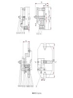
Processes can be combined into multiple-capability machines, known as machining centers. The machining center shown
in Fig. 2 is capable of performing the machining processes normally performed on a milling machine, drilling machine,
and a boring mill and is numerically controlled. The position and velocity of the tool with respect to the work is under
feedback control. Different tools can be automatically inserted into the spindle as needed to do different machining
processes. The horizontal spindle machine shown in Fig. 2 was one of the first NC machining centers to be able to change
workpiece pallets.
Fig. 2 Numerically controlled machining center that can change workpieces as well as cutting tools.
Courtesy of
Kearney and Trecker Corporation
For each of the basic machine tool types, there are many different kinds of workholders, cutting tools, and cutting tool
holders, resulting in a rather formidable list of equipment and processes. In this Volume, a Section entitled "Fundamentals
of the Machining Process" is presented first, with the intent of putting these processes into perspective and helping the
reader to understand the problems associated with using machining processes in the manufacture of products.
Overview of Machining Process Variables
Metal cutting processes can be viewed as consisting of independent (input) variables, dependent variables, and
independent-dependent interactions or relationships. The engineer or machine tool operator has direct control over the
input variables and can specify or select them when setting up the machining process. Several input variables are
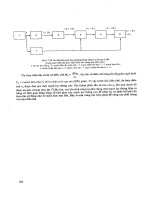
described below. Figure 3 summarizes the input/output relationships associated with metal cutting.
Fig. 3 Input/output relationships in metal cutting (machining)
Independent Input Variables
Workpiece Material. The metallurgy and chemistry of the workpiece can either be specified or is already known.
Quite often, a material is selected for a particular application chiefly because it machines well. Cast iron and aluminum,
for example, are known to machine easily. Other metals, such as stainless steel or titanium, are difficult to machine. They
often have large cutting forces or poor surface finishes, which can result in short cutting tool life, yet these metals are
selected to meet other functional design criteria. Machining practice for specific workpiece materials are reviewed in the
Section "Machining of Specific Metals and Alloys" in this Volume.
Starting Geometry. The size and shape of the workpiece may be dictated by preceding processes (casting, forging,
forming, and so forth) or may be selected from standard machining stock (for example, bar stock for screw machines).
Usually this variable directly influences the machining process or processes that are selected, as well as the depths of cut.
Specific Machining Processes. The selection of machining processes required to convert the raw material into a
finished product must be based on the geometry of the part (size and shape, rotational or non-rotational), the required
finishes and tolerances, and the quantity of the product to be made. Machining processes can be grouped into three broad
categories. These include traditional chip formation processes, abrasive machining processes, and nontraditional
machining processes.
Chip Formation Processes. As described earlier, there are seven basic chip formation processes: turning, shaping,
milling, drilling, sawing, broaching, and abrasive machining. The equipment and principles of operation associated with
each of these processes (with the exception of abrasive machining, which is treated separately) are described in the
Section titled "Traditional Machining Processes" in this Volume.
Abrasive machining is the basic process by which chips are formed by very small cutting edges that are integral parts
of abrasive particles. The principles of abrasive machining, the fundamental differences between metal cutting and
grinding, and the abrasives and equipment used for abrasive machining operations are described in the Section "Grinding,
Honing, and Lapping" in this Volume.
Nontraditional Machining Processes. Machining processes that involve compression/shear chip formation have a
number of inherent disadvantages. These include:
• High costs incurred with chip formation (high energy output and chip removal, dispo
sal, and/or
recycling)
• Heat buildup that often results in workpiece distortion
• High forces that create problems in holding the workpiece and which can also cause distortion
• Undesirable cold working and residual stresses in the workpiece that often neces
sitate further processing
to remove the harmful effects
• Limitations as to the size and delicacy of the workpiece
In order to avoid these limitations, nontraditional machining processes are increasingly being used. Nontraditional
methods usually do not produce chips or a lay pattern in the surface and often involve new energy modes (see the Section
"Nontraditional Machining Processes" in this Volume). Volumetric material removal rates, however, are much lower than
with traditional machining processes.
Tool Materials. The three most common cutting tool materials currently in use for production machining operations are
high-speed steel (HSS), both in wrought and powder metallurgy (P/M) form; carbides; and coated tools. Cubic boron
nitride (CBN), ceramics, and diamonds are also being widely employed. Generally speaking, HSS is used for general-
purpose tools, for tools of complex design or for tools used when cutting speeds are more modest. Carbide and ceramic
tool materials, which can operate at faster cutting speeds, come in a wide variety of grades and geometries. Titanium
nitride and titanium carbide coatings for HSS and carbides are now commonplace. Selection of a tool material that
provides reliable service while fulfilling the functional requirements is still an art. The harder the tool material, the better
it can resist wear at faster cutting speeds. The faster the cutting speed, the higher the cutting temperature and the shorter
the tool life. Retention of hardness at elevated temperatures as well as long tool life are desirable characteristics in cutting
tools. See the Section "Cutting Tool Materials" in this Volume for descriptions of the processing, properties, and
applications associated with the aforementioned materials.
Cutting Parameters. For every machining operation, it is necessary to select a cutting speed, a feed, and a depth of
cut. Many factors impinge on these decisions because all of the dependent variables are influenced by them. Proper
selection of variables also depends on the other input variables that have been selected; that is, the total amount of
material to be removed, the workpiece and tool materials, and the machining process or processes. These need to be
selected before preliminary choices for speed, feed, and depth of cut can be made.
Tool Geometry. Cutting tools are usually designed to accomplish specific operations, and thus the tool geometry
(angles) is selected to accomplish specific machining functions. Generally speaking, large rake and clearance angles are
preferred, but they are possible only on HSS tools. Tools made from carbides, ceramics, and other very hard materials
must be given small tool angles, which keep the tool material in compression during machining and thereby avoid tensile
failure and brittle fractures of the tool. The greater the precision required of the process, the better the geometry of the
cutting edge itself must be.
Workholding Devices. Workpieces are located (held in specific position with respect to the tools) and clamped in
workholding devices in or on the machine tools. For every machine tool, there are many different kinds of workholding
devices, ranging from general-purpose vises to specifically designed jigs and fixtures (see the article "Proper Fixturing" in
this Volume). The workholding devices are the key to precision manufacturing; thus, the selection (or design and
construction) of the correct workholding devices is every bit as important as the selection of the right cutting tool and
machine tool.
Cutting Fluids. The selection of the right cutting fluid for a particular combination of work material and tool material
can mean the difference between success and failure in almost every production machining process. Cutting fluids serve
to cool the workpiece, tool, and chips; reduce friction by means of lubrication; carry the chips away from the cutting
region; help improve the surface finish; and provide surface protection to the workpiece (a more complete discussion may
be found in the article "Metal Cutting and Grinding Fluids" in this Volume).
Dependent Variables
Dependent variables are determined by the process based on the prior selection of the input or independent variables.
Thus, the manufacturing engineer's control over these is usually indirect. The important dependent variables are cutting
force and power, size and properties of the finished product, surface finish, and tool wear and tool failure.
Cutting Force and Power. To machine metal at a specified speed, feed, and depth of cut, with a specified lubricant,
cutting tool material, and geometry, generates cutting forces and consumes power. A change in any of the variables alters
the forces, but the change is indirect in that the engineer does not specify the forces, only the parameters that generate
those forces. Forces are important in that they influence the deflections in the tools, the workpieces, and the workholders,
which in turn affect the final part size. Forces also play a roll in chatter and vibration phenomena common in machining.
Obviously, the manufacturing engineer would like to be able to predict forces (and power) so that he can safely specify
the equipment for a manufacturing operation, including the machine tool, cutting tool, and workholding devices. The
basic concepts associated with the modeling and understanding of cutting forces and power are explained in the article
"Forces, Power, and Stresses in Machining" in this Volume.
Size and Properties of the Finished Product. Ultimately, the objective of machining is to obtain a machined
surface of desired size and geometry with the desired mechanical properties. Because machining is a localized, plastic
deformation process, every machined surface will have some residual deformation (stresses) left in it. These residual
stresses are usually tensile in nature and can interact with surface flaws to produce part failure from fatigue or to cause
corrosion. In addition, every process has some inherent process variability (variations about average size) that changes
with almost all of the input variables. Thus, the manufacturing engineer must try to select the proper levels of input
variables to produce a product that is within the tolerance specified by the designer and has satisfactory surface properties.
Surface Finish. The final finish on a machined surface is a function of tool geometry, tool material, workpiece material,
machining process, speed, feed, depth of cut, and cutting fluid. Surface finish is also related to the process variability.
Rough surfaces have more variability than smooth surfaces. Often it is necessary to specify multiple cuts, that is, roughing
and finish cuts, to achieve the desired surface finish, or it may be necessary to specify multiple processes, such as
following turning with cylindrical grinding, in order to obtain the desired finish. The effect of various machining
processes on surface finish and on the properties of the final products are described in the article "Surface Finish and
Surface Integrity" in this Volume.
Tool Wear and Tool Failure. The plastic deformation and friction inherent in machining generate considerable heat,
which raises the temperature of the tool and lowers its wear resistance. The problem is subtle, but significant. As the tool
wears, it changes in both geometry and size. A dull cutting edge and change in geometry can result in increased cutting
forces that in turn increase deflections in the workpiece and may create a chatter condition. The increased power
consumption causes increased heat generation in the operation, which accelerates the wear rate. The change in the size of
the tool changes the size of the workpiece. Again, the engineer has only indirect control over these variables. He can
select slow speeds, which produce less heat and lower wear rates, but which decrease the production rates because the
metal removal rate is decreased. Alternatively, the feed or depth of cut can be increased to maintain the metal removal
rate while reducing the speed. Increasing either the feed or depth of cut directly increases the cutting forces. Therefore,
while tool life may be gained, some precision may be lost due to increased deflection and chatter. Wear mechanisms,
determination of modes of tool failure, and tool life testing are examined in the article "Tool Wear and Tool Life" in this
Volume.
Relations Between Input Variables and Process Behavior
Understanding the connections between input variables and process behavior is important knowledge for the
manufacturing engineer. Unfortunately, this knowledge is difficult to obtain. Machining is a unique plastic deformation
process in that it is constrained only by the cutting tool and operates at very large strains and very high strain rates. The
tremendous variety in the input variables results in an almost infinite number of different machining combinations.
Basically, there are three ways to deal with such a complex situation.
Experience requires long-term exposure, because knowledge is basically gained by trial and error, with successful
combinations transferred to other, "similar" situations. This activity goes on in manufacturing every time a new material
is introduced into the production facility. It took years for industry to learn how to machine titanium. Unfortunately, the
knowledge gained through one process may not transfer well to another even though their input variables appear very
similar.
Experiments. Machining experiments are expensive, time consuming, and difficult to carry out. Tool life experiments,
for example, are quite commonly done, yet tool life data for most workpiece/tool material combinations are not available.
Even when laboratory data have been published, the results are not necessarily transferable to the particular machine tools
and cutting tools on the shop floor. Tool life equations are empirically developed from turning experiments in which all
input variables except cutting speed are kept constant. The experimental arrangement may limit the mode of tool failure to
wear. Such results are of little value on the shop floor, where tools can and do fail from causes other than wear.
Theories. There have been many attempts to build mathematical models of the metal cutting process. Many of the
theories are extensions of the mechanics presented in the following Section, "Fundamentals of the Machining Process."
These theories try to predict the direction of the shearing process of metal cutting. These models range from crude, first-
order approximation to complex, computer-based models using finite-element analysis. Recently, some modest successes
have been reported in the literature in which accurate predictions of cutting forces and tool wear were made for certain
materials. Clearly such efforts are extremely helpful in understanding how the process behaves. However, the theory of
plastic deformation of metals (dislocation theory) has not yet been able to predict values for shear stresses and tool/chip
interface from the metallurgy and deformation history of the material. Therefore, it has been necessary to devise two
independent experiments to determine the shear strength (
s
) of the metal at large strains and high strain rates and the
sliding friction situation at the interface between the tool and chip (see the article "Mechanics of Chip Formation" in this
Volume).
Future Trends
The metal cutting process will continue to evolve, with improvements in cutting tool materials and machine tools leading
the evolution. More refined coatings on cutting tools will improve tool life and reliability, as will more robust, rigid
machine tools. The challenge for machining will involve dealing with the new types of materials that will need to be
machined, including aluminum and titanium alloys, alloy steels, and superalloys. These materials, because of improved
processing techniques, are becoming stronger and harder and therefore more difficult to machine. The objective should be
to design and build cutting tools that have less variability in their tool lives rather than longer tool lives. The increasing
use of structural ceramics, high-strength polymers, composites, and electronic materials will also necessitate the use of
nontraditional methods of machining. In addition, grinding will be employed to a greater extent than in the past, with
greater attention to creep feed grinding and the use of superabrasives (diamond and cubic boron nitride).
As the cutting tools improve, the machine tools will become smarter, with on-board computers providing intelligent
algorithms interacting with sensory data from the process. Programmable machine tools, if equipped with the proper
sensors, are capable of carrying out measurements of the product as it is being produced. These product data will be fed
back to the control program, which is then modified to improve the product or corrected for errors. Thus, the machine will
be able to make the adjustments necessary to prevent defective products from being produced. The goal of such control
programs should be improved quality (designed not to make a defect), rather than optimum speed or lowest cost.
Advancements in computer-aided machining processes are discussed in the Section "Machine Controls and Computer
Applications in Machining" in this Volume.
Another area in which significant advances will be made is the design of workholders that are capable of holding various
parts without any downtime for setups. Included in this search for flexible fixtures will be workholding devices that can
be changed over by a robot the same robot used to load or unload parts from the machine.
Mechanics of Chip Formation
J.T. Black, Auburn University
Introduction
THE BASIC MECHANISM involved in metal cutting is that of a localized shear deformation on the work material
immediately ahead of the cutting edge of the tool. The relative motion between the tool and the workpiece during cutting
compresses the work material near the tool and induces a shear deformation (called the primary deformation), which
forms the chip. The chip passes over the rake face of the cutting tool and receives additional deformation (called the
secondary deformation) because of the shearing and sliding of the chip against the tool.
These two plastic deformation processes have a mutual dependence. The material element that rubs the rake face has been
heated and plastically deformed during its passage through the primary shear process; therefore, the secondary process is
influenced by the phenomena on the shear plane. At the same time, the shear direction is directly influenced by the rake
face deformation and friction processes. The shear direction influences the heating and straining of the chip in the primary
process. In terms of metal cutting theory, this means that shear stress and shear direction must be determined
simultaneously. Such theoretical analyses are usually based on the mechanics of the process.
This article will review the following:
• The fundamental nature of the deformation process associated with machining
• The principles of the orthogonal cutting model
• The effect of workpiece properties on chip formation
• The mechanics of the machining process
Additional information on the modeling and analysis of chip formation can be found in the article "Forces, Power, and
Stresses in Machining," which immediately follows in this Section.
Fundamental Mechanism of Metal Deformation
Cutting Models. Before the mechanics of machining are presented, a brief discussion of the fundamental nature of the
deformation processes is helpful in understanding the assumptions that accompany the mechanics. The machining
geometry can be simplified from the three-dimensional (oblique) geometry, which typifies most industrial processes, to a
two-dimensional (orthogonal) geometry. Figure 1 compares the oblique and the orthogonal cutting geometries.
Orthogonal machining can be obtained in practice by:
• End cutting a tube wall by turning (Fig. 1b)
• Machining a plate as shown in Fig. 2
Oblique cutting is obtained when the cutting edge and the cutting motion are not perpendicular to each other. Because the
orthogonal case is more easily modeled, it will be used in this article to describe the deformation process.
Fig. 1 Comparison of oblique and orthogonal geometry machining. (a) Three-force oblique machining. F
c
is the
primary cutting force, F
f
is the feed force, and F
r
is the radial or thrust force. (b) Two-
force orthogonal
machining. F
c
is the measured cutting force, and F
t
is the feed (tangential) force. A tube-
cutting application is
shown; the cutting edge of the tool is perpendicular to the direction of motion. (c) For orthogonal cutting, the
shear area, A
s
occurs for a shear angle , width of cut w, and feed t.
Fig. 2 Development of the shear front-
lamella structure. As shown by this orthogonal geometry, shear
deformation evolves from a radial compression zone. See Fig. 5
for an explanation of the effects of shear
deformation on area p-q-r-s.
In the orthogonal cutting of a tube (Fig. 1b), the width of the cut is equal to the thickness of the tube wall, w. The
direction of shear is specified by the shear angle. The cross-sectional area of the chip is given by t
c
· w
c
, where t
c
is chip
thickness and w
c
is the width of the chip. The cutting edge of the tool is perpendicular to the feed direction. The measured
horizontal cutting force, F
c
, is the force in the direction of the cutting velocity (or cutting speed). The force in the
direction of the feed (vertical or tangential) and perpendicular (orthogonal) to F
c
is denoted by F
t
. With this two-
dimensional model of chip formation, the influence of the most critical elements of the tool geometry (rake angle, , and
the edge radius of the tool) and the interactions that occur between the tool and the chip can be more easily examined.
Shear Zone. Basically, the chip is formed by a localized shear process that takes place over very narrow regions.
Classically called the shear zone or shear plane, this deformation evolves out of a radial compression zone that travels
ahead of the shear process as the tool passes over the workpiece (Fig. 2). Like all plastic deformations, this radial
compression zone has an elastic compression region that converts to a plastic compression region as the material
approaches the cutting edge. This plastic compression generates dense dislocation tangles and networks in annealed
metals. When this work-hardened material reaches the tool, the material shears in the direction of the free surface.
Shear Front-Lamella Structure. The shear process itself is a nonhomogeneous (discontinuous) series of shear fronts
(or narrow bands) that produce a lamellar structure in the chips. This fundamental structure occurs on the microscale in all
metals when they are machined and accounts for the unique behavior of the machining process.
Individual shear fronts (Fig. 2) coalesce into narrow shear bands. The shear bands are very narrow (20 to 200 nm)
compared to the thickness of a lamella (2 to 4 m) and account for the large strain and high strain rates that typify this
process.
These fundamental structures are difficult to observe in normal metal cutting, but can be readily observed in a scanning
electron microscope with specially prepared workpieces. Figure 3 shows micrographs from an orthogonal machining
experiment performed inside a scanning electron microscope. The fundamental shear front-lamella structure is readily
observed. The side of the workpiece has been given a mirror polish so that the shear fronts can be observed. The shear
fronts are produced by the activation of many dislocations traveling in waves from the tool tip to the free surface. The
lamella represents heavily deformed material that has been segmented by the shear fronts. When machined, all metals
deform by this basic mechanism. The shear fronts relieve the applied stress.
Fig. 3 Ch
ip formation process viewed inside a scanning electron microscope. The workpiece is a rectangular
plate of high-
purity gold that was polished on the sides so that the plastic deformation of the shear process can
be readily observed. The boxed area in (a),
which is shown at a higher magnification in (b), shows the shear
fronts, numbered 1 and 2, advancing from the tool tip region toward the free surface of the workpiece. The
letter D indicates a defect on the side of the chip. The arrows indicate a scratch (
S) that has been sheared. The
tool has been withdrawn from the workpiece. In (c), the tool has been reinserted and slightly advanced. This
produced additional shear on shear front No. 2 and new shear front No. 3. Note the movement of defect D.
These shear
fronts are difficult to observe unless the specimen is polished and examined in a scanning electron
microscope.
Chips are sometimes produced with a sawtooth pattern on the top side the side that did not rub against the tool. This
sawtooth pattern is not produced by the shear front-lamella structure but rather by the unloading of the elastic energy
stored in the tool and workpiece, which results in chatter and vibration during cutting. The shear front-lamella structure
can and does exist without any vibration of the tool or workpiece. If each sawtooth were to be observed in the scanning
electron microscope, many fine shear front-lamella structures would be found in each sawtooth region. The geometry of
the sawtooth can be changed (even eliminated) by altering the rigidity of the setup or the machine. The shear front-
lamella structure is fundamental to, and characteristic of, the plastic deformation process itself; therefore, it is relatively
invariant with respect to cutting parameters and certainly cannot be eliminated.
Orthogonal Machining Fundamentals
Orthogonal machining setups are used to model oblique machining processes. Processes such as turning, drilling, milling,
and shaping are all three-force, or oblique, cutting methods. However, the orthogonal model shown in Fig. 4 is an
excellent illustration of the behavior of oblique processes without the complications of the third dimension.
Fig. 4 Schematics of orthogonal metal cutting mechanics. (a) Orthogonal model. t, uncut chip thickness (feed
or depth or cut); t
c
, chip thickness; , shear angle; , back rake angle; , clearance angle; , edge angle [
= 90 - ( + )]. (b) Velocity triangle. V
s
, shear velocity; V
c
, chip velocity; V
, cutting velocity. (c) Chip
freebody diagram. F, friction force; N, normal to friction force; F
s
, shear force; F
n
, normal to shear force; F
c
,
cutting force; F
t
, tangential force; R, resultant force
Chip Ratio. As described earlier in this article, orthogonal machining can be accomplished by machining a plate or can
be approximated by cutting the end of a tube wall in a turning setup. For the purposes of modeling, the following are
assumed: The shear process is a plane, the cutting edge is perfectly sharp, and there is no friction contact between the
flank of the tool and the workpiece surface. Because plane-strain conditions are assumed, the chips are assumed to have
no side flow (w = w
c
, Fig. 1c), and the cutting velocity is constant. The shear process occurs at angle for a tool with
back rake angle . The chip has velocity V
c
and makes contact with the rake face of the tool over length (Fig. 2).
Defining the ratio of the uncut chip thickness, t, to the chip thickness, t
c
, as the chip ratio, r, produces the following:
(Eq 1)
Solving Eq 1 for yields:
(Eq 2)
In practical tests, the average chip thickness can be obtained by carefully measuring the length L and the weight W of a
piece of a chip. Then:
(Eq 3)
where is the density of the work material and t is the feed or uncut chip thickness. Chip thickness is usually greater than
the depth of cut, t, and is constrained by the rake face of the cutting tool.
Shear Angle. There are numerous other ways to measure or compute the shear angle, both during (dynamically) the
cutting process and after (statically) it has been halted. The shear angle can be measured statically by instantaneously
interrupting the cut through the use of quick-stop devices. These devices disengage the cutting tool from the workpiece
while cutting is in progress, leaving the chip attached to the workpiece. Optical microscopy and scanning electron
microscopy are then used to observe the shear angle. High-speed motion pictures have also been used to observe the
process at frame rates as high as 30,000 frames per second. More recently, machining stages have been built that allow
the process to be performed inside a scanning electron microscope and recorded on video-tape for high-resolution, high-
magnification examination of the deformation process. The micrographs shown in Fig. 3 were created in this manner.
This technique has been used to measure the velocity of the shear fronts, V
c
, during cutting, thus verifying experimentally
that the vector sum of V and V
c
equals V
s
(Fig. 4b).
For constancy of volume, it was observed that:
(Eq 4)
Equation 4 indicates that the chip ratio (and therefore the shear angle) can be determined dynamically if a reliable means
of measuring chip velocity can be found. Thus, one could determine dynamically for a known tool geometry. Therefore,
cutting forces can be dynamically predicted, an important consideration in adaptive control machining (see the article
"Adaptive Control" in this Volume). Velocities are also important in power calculations, heat determinations, and
vibration analyses associated with chip formation.
Shear Strain. When an area of metal (for example, area p-q-r-s in Fig. 2) passes through the shear process, it is
plastically deformed into a new shape, as shown in Fig. 5. The amount of plastic deformation is related to the shear angle,
, and the rake angle, .
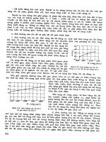
Fig. 5 Strain on shear plane, , versus shear plane angle, , for three values of rake angle,
Therefore, the chip undergoes a shear strain, , of:
(Eq 5)
The meaning of shear strain, as well as of the units in which it is measured, is shown in the inset diagram in Fig. 5. A unit
displacement of one face of a unit cube is a shear strain of 1 ( = 1). Figure 5 illustrates the relationship between the
shear strain in orthogonal cutting and the shear plane angle for three values of the rake angle. For any rake angle, there is
a minimum strain at which the mean chip thickness is equal to the feed (t
c
= t). For zero rake angle, this occurs at = 45°.
The change in shape of a unit cube after it passes through the shear plane for different values of the shear plane angle is
shown in the lower diagram in Fig. 5 for a tool with a zero rake angle. The minimum strain at = 45° is apparent from
the shape change. The shaded region in Fig. 5 shows the typical values of found in practice.
At a zero rake angle, the minimum shear strain is 2. The minimum strain occurs when there is no friction at the tool/chip
interface. The minimum strain decreases as the rake angle increases. If the rake angle is too large, the tool is weak and
will fracture. Rake angles larger than 30° are seldom used in industry. With carbides and ceramics, the tendency has been
to decrease the rake angle to make the tools more robust, allowing these harder but less tough tool materials to be used.
Therefore, even under optimum cutting conditions, chip formation involves very severe plastic deformation, resulting in
considerable work hardening and structural change. Metals and alloys lacking in ductility periodically fracture on the
shear plane, producing discontinuous chips (see the section "Effect of Work Material Properties" in this article).
In general, metal cutting strains are quite large compared to other plastic deformation processes, being of the order of 2 to
4 mm/mm (2 to 4 in./in.). However, this large strain occurs over very narrow regions (the shear band), which results in
extremely high shear strain rates, typically of the order of 10
4
to 10
8
mm/mm (10
4
to 10
8
in./in.). This strain rate can be
estimated from:
(Eq 6)
where d is the thickness of the shear bands. This combination of large strains and high strain rates operating within a
process constrained only by the workpiece and the tool (actually, the deformation interface at the rake face of the tool)
causes great difficulties in theoretical analyses of the process.
Effect of Work Material Properties
Principal Chip Types. The properties of the work material control chip formation. Work material properties include
yield strength, shear strength under compressive loading, strain-hardening characteristics, friction behavior, hardness, and
ductility. As noted in the section "Shear Strain" in this article, work material ductility is an important factor. Highly
ductile materials not only permit extensive plastic deformation of the chip during cutting, which increases work, heat
generation, and temperature, but also result in longer, continuous chips that remain in contact longer with the tool face,
thus causing more frictional heat. Chips of this type are severely deformed and have a characteristic curl. On the other
hand, some materials, such as gray cast iron, lack the ductility necessary for appreciable plastic chip formation.
Consequently, the compressed material ahead of the tool can fail in a brittle manner anywhere ahead of the tool,
producing small fragments. Such chips are termed discontinuous or segmented (Fig. 6).
Fig. 6 Three characteristic types of chips. (a) Discontinuous. (b) Continuous. (c) Continuous with built-up edge
The cutting parameters also influence chip formation. Cutting parameters include tool materials, tool angles, edge
geometries (which change due to wear, cutting speed, feed, and depth of cut), and the cutting environment (machine tool
deflections, cutting fluids, and so on). Further complications result from the formation of the built-up edge on the cutting
tool.
A built-up edge is work material that is deposited on the rake face near the cutting edge (Fig. 6c). It is the product of
the localized high temperature and extreme pressure at the tool/chip interface. The work material adheres to the cutting
edge of the tool (similar to a dead-metal zone in extrusion). Although this material protects the cutting edge, it also
modifies the geometry of the tool. Built-up edges are not stable and will slough off periodically, adhering to the chip or
passing under the tool and adhering to the machined surface. Built-up edge formation can often be eliminated or
minimized by reducing the depth of the cut, increasing the cutting speed, using positive rake tools, or applying a coolant,
but these techniques greatly increase the complexity of the chip formation process analysis.
Mechanics of Machining
Orthogonal machining has been defined as a two-component force system, while oblique cutting involves a three-force
situation. Figure 4(c) shows a free body diagram of a chip that has been separated at the shear plane. The resultant force R
consists of the friction force, F, and the normal force, N, acting on the tool/chip interface contact area (length times
width w). The resultant force R' consists of a shear force, F
s
, and a normal force, F
n
, acting on the shear plane area, A
s
.
The forces R and R' are assumed to be equal, opposite, and colinear. Determination of these forces necessitates a third set
that can be measured. A dynamometer, mounted in the workholder or the toolholder, can be used to measure F
c
and F
t
.
This set has resultant R'', which is equal in magnitude and colinear to the other resultant forces in the diagram. To express
the desired forces (F
s
, F
n
, F, N) in terms of the dynamometer components F
c
and F
t
and appropriate angles, a circular
force diagram is developed in which all six forces are collected in the same force circle. This is shown in Fig. 7. In Fig. 7,
is the angle between the normal force, N, and the resultant force R. It is used to describe the friction coefficient, , on
the tool/chip interface area, which is defined as F/N so that:
(Eq 7)
The friction force, F, and its normal force, N, can be shown to be:
F = F
c
sin + F
t
cos
(Eq 8)
N = F
c
cos -F
t
sin
(Eq 9)
where