Volume 15 - Casting Part 7 potx
Bạn đang xem bản rút gọn của tài liệu. Xem và tải ngay bản đầy đủ của tài liệu tại đây (4.18 MB, 150 trang )
Vertical Feeding of Ingots. Refractory and reactive metal ingots of high purity, homogeneity, and smooth surface are
remelted by vertical feeding (Fig. 35d). The molten metal droplets run down the conical, rotating electrode tip, are
refined, and then drop into the pool center. The crucible pool is normally of the same diameter as the electrode but is
sometimes smaller or larger. It is kept in the liquid state to allow final refining and to guarantee ingot homogeneity.
Because two or more electron guns are used, the entire pool can be equally bombarded; thus, shadow effects of the
electrode can be eliminated.
Simultaneous melting of horizontally and vertically fed electrodes (Fig. 35e) can be used for the production of critical
alloys. In this case, the feedstock should be of the desired purity.
Horizontally Fed Ingots. Drip melting of horizontally fed material with a single electron gun (Fig. 36) is used for
refining some steel alloys in East Germany and other Soviet bloc countries. In this process, the feedstock size is smaller
than the pool diameter to minimize the shadow effect of the horizontally fed bar. In production units, feeding can be
carried out from two opposite sides.
Fig. 36 Drip melting of 330 mm (13 in.) square steel billet in a 1100 kW single-
gun furnace. Melt rate: 1000
kg/h (2200 lb/h). Courtesy of VEB-Edelstahlwerk, East Germany.
Other Process Considerations. To ensure the production of clean, homogeneous metals and alloys in electron beam
drip melting furnaces, various aspects of material processing and handling must be controlled. Key considerations
include:
• Dimensions and quality of the feedstock, and the feeding system used
• Ingot cooling and unloading during melting of another ingot
• Passivation and removal of condensates from the melt chamber
• Planning of melt sequences to minimize the number of furnace cleanings required
• Routine preventive furnace maintenance to ensure reliability
• Operator skill in operation of the furnace
• Material yield and energy consumption
Equipment for Drip Melting
The essential equipment groups required for drip melting melting furnaces, control systems, and power supply units are
all important for achieving optimum productivity.
The melting furnace (Fig. 37) includes the electron beam gun as the heat source, material feeding and ingot
withdrawal systems, a crucible for material solidification, and a vacuum system to maintain the low pressure. Process
observation, both visually and with video systems, is possible through viewports. The melt chamber flanges are equipped
with x-ray absorbing steel boards, and interlocking systems prevent operation failures and accidents.
Fig. 37 Single-gun 1200 kW fur
nace for horizontal drip melting of steels. Melting rates of up to 1100 kg/h
(2425 lb/h) are possible.
The control system allows the adjustment and control of such operating process parameters as electron beam power,
operating vacuum level, material feed rate, and ingot withdraw speed. The control system also records and logs the
process data.
Power Supply Units. One or more high-voltage power supply units are needed to supply the electron beam guns with
the required continuous voltage (30 to 40 kV). The beam power of each gun can be adjusted between zero and maximum
power with an accuracy of ±2%.
Other Equipment. Large production furnaces are equipped with lock-valve systems to allow simultaneous melting and
unloading of ingots without breaking the vacuum in the melt chamber. Production is thus limited only when the
condensate remaining in the melt chamber requires cleaning or when a different alloy is to be melted.
Characteristics of Electron Beam Drip Melted Metals
Electron beam melted and refined material is of the highest quality. The amount of interstitials present is very low, and
trace elements of specific high vapor pressure can also be reduced to very low values (Ref 37, 38).
Reactive and Refractory Metals
Tantalum and niobium ingots have smooth surfaces and are of sufficient ductility that they can be cold worked, and
sheets and wires can be produced.
Tungsten and molybdenum ingots are also of the highest possible purity, but the ingots are brittle because of the
very large grain size and the concentration of impurities at grain boundaries.
Hafnium. Electron beam melted hafnium is of higher ductility than the vacuum arc remelted metal (Ref 39). The main
application of electron beam melted hafnium is as control elements for submarine nuclear reactors.
Vanadium is refined by electron beam drip melting. The aluminothermically produced feedstock is drip melted in
several steps. During this procedure, the ingot diameter is reduced at each step by approximately 30 to 40 mm (1.2 to 1.6
in.) to obtain an ingot 30 to 40 mm (1.2 to 1.6 in.) in diameter, regardless of the initial ingot diameter. The clean
vanadium ingots are primarily used in nuclear reactor applications (Ref 40).
Applications for electron beam melted refractory and reactive metals are listed in Table 6.
Table 6 Principal applications for vacuum arc remelted (VAR), electron beam melted (EB), and powder
metallurgy (P/M) reactive and refractory metal ingots
Metal Applications
Reactive metals, VAR and EB melting
Hafnium Flash bulbs and glow discharge tubes for the electronics industry; control rods and breakoff elements in submarine
nuclear reactors
Vanadium Targets for high deposition rate sputtering processes in the electronics industry; breakoff elements, fixtures, and fasteners
in nuclear reactors; standards for basic research; alloying element for certain high-purity alloys
Zirconium Getter material in tubes in the electronics industry; stripes for flash bulbs; fuel claddings, fasteners, and fixtures for
nuclear reactors
Titanium Components for bleaching equipment and desalination plants in the chemical industry; superconductive wires; turbine
engine disks, blades and housings, rain erosion boards, landing legs, wing frames, missile cladding, and fuel containers in
the aircraft and aerospace industries shape memory alloys; biomedical fixtures and implants; corrosion resistant claddings
Refractory metals, EB melting and P/M
Tungsten Heating elements, punches and dies, and nonconsummable electrodes for arc melting and gas tungsten arc welding for
metal processing equipment; targets for x-ray equipment and high sputtering rate devices such as very large-scale
integrated circuits, cathodes and anodes for electronic vacuum tubes in the electronics industry; radiation shields in the
nuclear industry; cladding and fasteners for missile and reentry vehicles
Tantalum Condensers, autoclaves, heat exchangers, armatures, and fittings for the chemical industry; electrolytic capacitors for the
electronics industry; surgical implants; fasteners for aerospace applications
Molybdenum
Dies for conventional and isothermal forging equipment; electrodes for glass melting; targets for x-ray equipment;
cladding and fasteners for missile and reentry vehicles
Niobium Superconductive wire for energy transmission and large magnets for the electrical and electronics industries; heavy ion
accelerators and radio frequency cavities for nuclear applications; components for aircraft and aerospace applications
Steels
The purity and properties of electron beam melted steels are in some respects better than those of vacuum arc and
electroslag remelted steels, but the processing costs are higher. The electron beam melting of steel is primarily used in
East Germany and other Soviet bloc countries. The resulting ingots are up to 1000 mm (40 in.) in diameter and weigh up
to 18 Mg (20 tons). The furnaces used have been in operation since 1965, and have beam powers of up to 1200 kW.
Larger furnaces for the production of ingots weighing up to 30 to 100 Mg (33 to 110 tons) are under construction (Ref
41).
The essential advantage of the electron beam melting of steel is the drastic reduction of metallic and nonmetallic
impurities and interstitial elements (Ref 42, 43). The principal applications for electron beam melted steels are in the
machinery industry for parts for which high wear resistance and long service life are required. The extended service lives
of the parts and the reduced manufacturing time (for example, less surface polishing is required for electron beam melted
steel) can justify the higher material costs.
The electron beam melting of steel and superalloys can become much more economical when melting and refining are
done by continuous flow melting or cold hearth refining. These melting and refining methods reduce energy costs and
minimize material losses.
References cited in this section
37.
R.E. Lüders, Tantalum Melting in a 800 kW EB Furnace, in Proceedings of the Bakish
Conference on Electron Beam
Melting and Refining (Reno, NV), R. Bakish, Ed., 1983, p 230-244
38.
J.A. Pierret and J.B. Lambert, Operation of Electron Beam Furnace for Melting Refractory Metals, in
Proceedings of
the Bakish Conference on Electron Beam Melting and Refining (Reno, NV), R. Bakish, Ed., 1984, p 208-218
39.
H. Sperner, Hafnium, Metallwis. Technik., Vol 7 (No. 16), 1962, p 679-682
40.
R. Hähn and J. Krüger, Refining of Vanadium Aluminium Alloys to Vanadium 99.9% by EB Melting, in
Proceedings
of the Bakish Conference on Electron Beam Melting and Refining (Reno, NV), R. Bakish, Ed., 1986, p 53-67
41.
J. Lambrecht, D. Rumberg, and K.H. Werner, Stand der Technologie der Stahlerzeugung im Elektronenstrahlofen mit
Blockmassen bis 100 t, Neue Hütte, Vol 10, Oct 1984
42.
C.E. Shamblen, S.L. Culp, and R.W. Lober, Superalloy Cleanliness Evaluation Using the EB Button Melt Test, in
Proceedings of the Bakish Conference on Electron Beam Melting and Refining (Reno, NV), R. Bakish, Ed., 1983
43.
F. Hauner, H. Stephan, and H. Stumpp, Ergebnisse bei Elektronenstrahl-
Schmelzen von gerichtet erstarrten
Knopfproben zur Identifizierung von nichtmetallischen Einschlüssen in hochreinen Superlegierungen, Metall.,
Vol 2
(No. 40), 1986, p 2-7
Continuous Flow Melting
The continuous flow melting process (cold hearth refining process) (Fig. 38) was developed approximately 10 years after
drip melting (Ref 44). Continuous flow melting is mainly used for refining specialty steels and superalloys and for
refining and recycling reactive metal scrap, especially Ti-6Al-4V from high-density tungsten carbide tool tips (Ref 45).
Fig. 38 Schematic of the continuous flow melting process.
Principles of Continuous Flow Melting
Continuous flow melting (Fig. 39) is the most flexible vacuum metallurgical melting process. It is a two-stage process in
which the first step (material feeding, melting, and refining) takes place in a water-cooled copper trough, ladle, or hearth.
In the second step, solidification occurs in one of several round, rectangular, or specially shaped water-cooled continuous
copper crucibles. Both process steps are nearly independent from each other; they are linked only by the continuous flow
of the liquid metal stream. The major refining actions are carried out in the hearth, but some postrefining takes place in
the pool of the continuous casting crucible, similar to the drip melting of horizontally fed billets. Refinement in
continuous flow melting occurs by vacuum distillation in the hearth pool, superheating, and stirring of the molten metal
pool.
Fig. 39 Four-gun 1200 kW combined electron beam drip melting and continuous flow melting furnace.
Removal of Impurities. Most impurities with densities lower than that of the melt (for example, metalloids in steels
and superalloys) can be segregated by flotation and formed into a slag raft. The raft is then held in place by either
mechanical or electrothermal means. Impurities denser than the melt, such as tungsten carbide tool tips in titanium, are
removed by sedimentation. Inclusions with densities such that efficient flotation or sedimentation does not occur can be
partially removed by adhesion to the slag raft.
Hearth dimensions are based on the type and amount of refining required. For example, hearths for vacuum distillation
should be nearly square and relatively deep to allow sufficient melt stirring. For flotation refining, the hearth should be
long and narrow (for superalloys, approximately 10 mm, or 0.4 in., of hearth length for each 100 kg/h, or 220 lb/h, of melt
rate is recommended). Hearths for titanium alloy scrap recycling can be relatively short if all the materials can be
transported to the pool of the hearth rather than to the ingot pool.
Feeding. Material feeding criteria include 100% homogenous material transportation to avoid uncontrolled evaporation
of alloying elements and correct feeding into or above the hearth pool. Horizontal feeding of compacted, premelted, or
cast material is most often used. Loose scrap and raw material are used only when compaction is too expensive. Feeding
of liquid metal was used in one of the first continuous flow melting furnaces to produce a ferritic steel in a vacuum
induction furnace (Ref 46). Postrefining was carried out in a cascade of five hearths 1.5 m (60 in.) long and 1 m (40 in.)
wide.
Casting and Solidification. The criteria for material casting and solidification include the shape of the final product
and the solidification rate required to avoid ingot tears or other defects and to ensure a homogeneous ingot structure. The
multiple casting of small ingots is sometimes used, especially when forging is impossible because of the brittleness of the
solidified material (for example MCrAly wear-resistant coating alloys). The casting of round and rectangular ingots and
slabs is common practice, and the continuous casting of hollow ingots is also being used (Ref 47). The casting of
segregation-free ingots and ingots with a fine grain size is under development to improve the workability of superalloys
(Ref 48, 49).
Continuous Flow Versus Drip Melting
Table 7 compares the essential features of drip melting and continuous flow melting. Generally, continuous flow melting
is used for all refractory metals, superalloys, and specialty steels, especially when flotation or sedimentation of inclusions
is required. Drip melting is used for refractory metals because of their high melting points and the resulting high heat
losses to the water-cooled copper crucible. Depending on production quantity, double or triple drip melting may require
less energy than a single continuous flow melt of some materials, such as niobium.
Table 7 Comparison of the characteristics of drip melting and continuous flow melting
Characteristic Refractory metals
Reactive metals, superalloys, and specialty steels
Power density High
Soft; smoothly distributed
Inclusions Irrelevant
Must be removed
Ingot shape and structure Round; coarse grain
Round or flat; fine grain, segregation-free
Mass production Low
High
Competitive economical processes
Vacuum arc remelting
Vacuum arc remelting; electroslag remelting
Preferred method Drip melting Continuous flow melting
Refining and Production Data
Data on continuous flow electron beam melting and refining in laboratory and pilot production furnaces are given in
Table 8. The data demonstrate the effectiveness of the process in reducing impurities and interstitial elements. It can also
be seen that the selective evaporation of chromium from superalloys can be controlled by the distribution of beam power
at the trough pool and by controlling trough pool area and melt rate. The selective evaporation of aluminum from Ti-6Al-
4V alloy is much more difficult to control; additional aluminum must be used to compensate for the aluminum
evaporated.
Table 8 Refining and production data for the continuous flow melting of reactive and refractory metals and stainless steels in laboratory and pilot
production furnaces
Composition of feedstock and product Metal Feedstock
size,
mm (in.)
Trough
size,
mm (in.)
Ingot size,
mm (in.)
Ingot
weight,
kg (lb)
Melt
rate,
kg/h
(lb/h)
Electron
beam
power,
kW
Operating
pressure,
Pa (torr)
Specific
melting
energy,
kW ·
h/kg
C,
ppm
O,
ppm
N,
ppm
H,
ppm
Al,
%
V,
%
Cr,
%
. . . 900 . . . . . . . . . . . .
. . . Hafnium 60 (2.4)
square
120 × 250
(5 × 10)
100 (4) diam 83.0 (183) 40 (88) 180 4 × 10
-2
(3 × 10
-4
)
4.5
. . . 600 . . . . . . . . . . . .
. . .
. . . 950 95 30 . . . . . .
. . . Zirconium 100 (4) square
120 × 300
(5 × 12)
150 (6) 90.5 (200) 42 (92.5) 185 3.5 × 10
-2
(2.6 × 10
-
4
)
4.4
. . . 540 30 3 . . . . . .
. . .
. . . 4000
800 10 . . . . . .
. . . Zirconium 80 (3.2)
square
120 × 300
(5 × 12)
100 (4) 40.2 (89) 80 (176) 140 3.5 × 10
-2
(2.6 × 10
-
4
)
1.75
. . . 1520
210 3 . . . . . .
. . .
. . . 1045
210 10 . . . 99 . . . Vanadium 50 (2) square 120 × 300
(5 × 12)
100 (4) . . . 20 (44) 130 1.5 × 10
-2
(1.1 × 10
-
4
)
6.5
. . . 277 50 3 . . . 99 . . .
400 2600
110 84 6.0 4.0
. . . Ti-6Al-4V Swarf 120 × 300
(5 × 12)
150 (6) 62.6 (138) 40 (88) 122 2 × 10
-2
(1.5 × 10
-
4
)
3.0
200 2700
110 22 4.4 4.2
. . .
Ti-6Al-4V Solid scrap 120 × 300
(5 × 12)
150 (6) 62.6 (138) 70 (154) 140 7 × 10
-2
(5.3 × 10
-
4
)
2.0 1520
1520
75 15 6.0 4.0
. . .
(5 × 12)
4
)
. . . 1320
76 8 4.8 4.1
. . .
. . . . . . . . . . . . 6.0 4.0
. . . Ti-6Al-4V 125 (5) diam 150 × 400
(6 × 16)
2 × 75 (3)
diam
2 × 32
(70.5)
91 (200) 147 6 × 10
-2
(4.5 × 10
-
4
)
1.61
. . . . . . . . . . . . 3.6 4.3
. . .
. . . . . . . . . . . . . . . . . .
. . . Commercially pure
titanium
160 (6.3) 150 × 250
(6 × 10)
100 × 400
(4 × 16)
96.4 (213) 86.3
(190)
148 6 × 10
-2
(4.5 × 10
-
4
)
1.71
. . . . . . . . . . . . . . . . . .
. . .
Commercially pure
titanium
Sponge 150 × 500
(6 × 20)
100 × 400
(4 × 16)
103.0 (227) 41.2 (91) 226 8 × 10
-2
(6 × 10
-4
)
5.5 . . . . . . . . . . . . . . . . . .
. . .
701 97 155 . . . . . . . . .
18.25
Stainless steel 150 (6) diam 150 × 400
(6 × 16)
2 × 75 (3)
diam
2 × 55 (121)
136 (300)
144 6 × 10
-2
(4.5 × 10
-
4
)
1.06
536 33 68 . . . . . . . . .
18.11
417 14 52 . . . . . . . . .
19.11
Alloy 718 133 (5.2)
diam
150 × 400
(6 × 16)
2 × 75 (3)
diam
2 × 57 (126)
136 (300)
156 6 × 10
-2
(4.5 × 10
-
4
)
1.15
363 17 34 . . . 0.72
. . .
18.73
AISI type 316 stainless
steel
150 (6) diam 150 × 400
(6 × 16)
3 × 65 (2.6)
diam
3 × 41.5
(91.5)
136 (300)
156 6 × 10
-2
(4.5 × 10
-
4
)
1.15 . . . . . . . . . . . . . . . . . .
. . .
Source: Ref 50
References cited in this section
44.
C.d'A. Hunt and H.R. Smith, Electron Beam Processing of Molten Steel in Cold Hearth Furnace, J. Met.,
Vol 18,
1966, p 570-577
45.
H.R. Harker, Electron Beam Melting of Titanium Scrap, in
Proceedings of the Bakish Conference on Electron Beam
Melting and Refining (Reno, NV), R. Bakish, Ed., 1983, p 187-190
46.
C.d'A. Hunt, H.R.
Smith, and B.C. Coad, The Combined Induction and Electron Beam Furnace for Steel Refining and
Casting, in Proceedings of the Vacuum Metallurgy Conference (Pittsburgh, PA), June 1969, p 1-22
47.
H.R. Harker, The Present Status of Electron Beam Melting Technology, in
Proceedings of the Bakish Conference on
Electron Beam Melting and Refining (Reno, NV), R. Bakish, Ed., 1986, p 3-7
48.
C.d'A. Hunt, J.C. Lowe, and T.H. Harrington, Electron Beam, Cold Hearth Refining for the Production of Nickel and
Cobalt Base Superalloys, in Proceedings of the Bakish Conference on Electron Beam Melting and Refining
(Reno,
NV), R. Bakish, Ed., 1984, p 295-304
49.
H. Stephan, R. Schumann, and H.J. Stumpp, Production of Superclean Fine-
Grained Superalloys for Improvement of
the Workability and Engine Efficiency by EB Melting and Refining Methods, in
Proceedings of the Eighth
International Conference on Vacuum Metallurgy (Linz), 1985, p 1219-1309
50.
H. Stephan, Production of Ingots and Cast Parts From Reactive Metals by Electron
Beam Melting and Casting, in
Proceedings of the Third Electron Beam Processing Seminar (Stratford, UK), 1974, p 1b1-1b69
Equipment for Continuous Flow Electron Beam Melting
The equipment required for continuous flow melting is different from that used in drip melting mainly because of the
trough and the somewhat larger melting chamber. In addition, because of the materials often melted in the continuous
flow process (superalloys and titanium alloys), additional instrumentation is often provided. This may include an ingot
pool level control system, metal vapor and partial pressure analyzers, a two-color temperature control system, and a data
logging system.
Accurate beam power distribution is achieved in two- or three-gun furnaces by microprocessor control, which allows the
splitting of a single beam to 64 locations and the adjustment of dwell time at each location between 0.01 and 1000 s. The
beam spot at each of the 64 locations can be scanned over an elliptical or rectangular area. With such systems, the
required refining can be achieved without unnecessary power consumption and evaporation of alloying elements (Ref 51).
Process observation is accomplished with a video monitoring system. Samples can be obtained from both the trough pool
and the ingot pool for nearly continuous control of material quality.
Feeding systems for continuous flow furnaces must maintain homogeneity along the length of the feed material. The
trough and crucible should be easily accessible for convenient maintenance, especially when different alloys are to be
melted in the same furnace.
Reference cited in this section
51.
H. Ranke, V. Bauer, W. D
ietrich, J. Heimerl, and H. Stephan, Melting and Evaporation With the Newly Developed
Leybold-Heraeus 600 kW EB Gun at Different Pressure Levels, in
Proceedings of the Bakish Conference on Electron
Beam Melting and Refining (Reno, NV), R. Bakish, Ed., 1985
Characteristics of Continuous Flow Melted Materials
Titanium ingots and slabs can be produced from titanium scrap contaminated with tungsten carbide tool tips. The
electron beam melted product contains tungsten carbide particles no larger than 0.7 mm (0.028 in.) in diameter. Oxygen
content can be reduced by fitting titanium sponge compacts around a forged ingot or slab. Continuous flow melted
titanium ingots can be directly remelted in a VAR furnace.
Superalloys. Continuous flow electron beam melted superalloy ingots 150 to 200 mm (6 to 8 in.) in diameter are often
used in VIM investment casting furnaces. Such ingots are nearly free of nonmetallic inclusions and trace elements (Ref
52). The simultaneous continuous casting of twin, triple, or multiple ingots is under development in a 200 kW pilot
furnace. Multi-ingot casting can become economical when 90 Mg (100 tons) or more of an alloy is being produced
annually (Ref 53).
References cited in this section
52.
M. Krehl and J.C. Lowe, El
ectron Beam Cold Hearth Refining for Superalloy Revert for Use in Foundry Production,
in Proceedings of the Bakish Conference on Electron Beam Melting and Refining
(Reno, NV), R. Bakish, Ed., 1986, p
286-296
53.
M. Romberg, R. Schumann, H. Stephan, and H.
Stumpp, Electron Beam Melting and Refining of Superalloys for
Ingot and Barstick Production, in Proceedings of the Bakish Conference on Electron Beam Melting and Refining
(Reno, NV), R. Bakish, Ed., 1986
Investment Casting Using Electron Beam Melting
Investment casting with electron beam heat sources from water-cooled copper skull crucibles has been used for the
production of superalloy turbine parts with directionally solidified or monocrystal structures and for titanium parts with
equiaxed structures. In both applications, the feedstock is clean material that is melted with no major refining effect and
without picking up any contamination. The process competes for superalloys with vacuum induction melting and
investment casting and for titanium with vacuum arc skull melting and casting.
Characteristics of Electron Beam Investment Casting
With electron beam melting, it is possible to superheat the casting material just before and during pouring to increase the
fluidity of the metal. This is not possible with vacuum arc skull melting. The extremely short metal flow path between the
crucible spout and the mold funnel reduces erosion of the mold, and the controllable pouring speed allows the use of
small mold funnels for reducing revert material. An essential advantage of electron beam titanium casting is the
possibility of using premelted VAR ingots and solid, clean in-house recycling scrap separately or simultaneously to
reduce material costs. The decisive advantage of electron beam casting technology is the possibility of process
automation, which guarantees reproducibility of quality and a high production rate. Therefore, electron beam melting is
used only when a high production rate is demanded. The obvious disadvantage is the decreasing metal temperature during
pouring caused by the temperature gradient of the melt in the water-cooled copper crucible; for this reason, the process
cannot be used for the production of superalloy cast parts with very specific equiaxed structures.
Process Technology and Equipment for Superalloy Castings
For the economical mass production of superalloy turbine parts, the electron beam casting process and equipment shown
in Fig. 40 and described in Table 9 meet the required process and product specifications. The pool temperature before
casting can be adjusted between 1650 and 1900 °C (3000 and 3450 °F), depending on part requirements. The adjusted
temperature can be reproduced with an accuracy of 0.3%.
Table 9 Processing data for the mass production of directionally solidified and monocrystal superalloy castings in 120 and 300 kW electron beam
casting machines
Machine
Maximum
electron
beam
power, kW
Ultimate vacuum
pressure,
Pa (torr)
Leak and
degassing
rate,
mbar · L/s
Electrode dimensions,
mm (in.)
Number of
electrodes
per
magazine
Casting
weight,
kg (lb)
Average
weight
deviation,
%
Cycle
time,
s
Pool surface
temperature
at pouring,
°C ( °F)
Average
temperature
deviation,
%
Material loss by
evaporation and
splattering, %
120 kW 120 2 × 10
-4
(1.5 × 10
-6
)
2 × 10
-4
125 (5) diam; 1600 (63) long 12 0.45 (1)
1.8 60 1850 (3360) 0.3
1.5
300 kW 300 2 × 10
-4
(1.5 × 10
-6
)
2 × 10
-4
125 (5) diam; 1600 (63) long
12 8 (18) 1.5 440 1850 (3360) 0.3 1.5
Specific
electron
beam energy
Step
Function Time,
s
Electron
beam
power, kW
kW/kg
kW/lb
A Heating of electrode tip and positioning into melting area 4 80 0.20 0.090
B Distribution of electron beam power to the electrode only 0.5 80 0.02 0.009
C Drip melting of rotating electrode with simultaneous droplet counting and
weight control
35 80 1.72 0.78
D Retraction of electrode and distribution of increased power to the melt pool 0.5 100 0.74 0.33
E Pool superheating 12 100 0.74 0.33
F Pouring with simultaneous pool superheating 0.7 100 0.04 0.33
G Washing of crucible for reduction of skull weight 6.0 60 0.22 0.10
H Cleaning of the spout lip to obtain reproducible pouring streams; tilting back of
crucible
1.0 60 0.04 0.02
Fig. 40
Procedure and process data for the electron beam melting and casting of 0.45 kg (1 lb) superalloy
parts. Cycle time: 60 s; total electron beam energy: 3.01 kW · h/s.
The accuracy of the part weight was 1.8% for small parts (450 g, or 1 lb) and 1.5% for larger parts (8 kg, or 18 lb). The
cycle time for smaller parts was 58 ± 1.5 s; for larger parts, 300 ± 10 s.
Reduction in chromium content was less than 0.1%. Feedstock load is twelve electrodes 125 mm (5 in.) in diameter and
1600 mm (63 in.) long. The electrode magazine can be reloaded without venting the melt chamber. Exchange of water-
cooled copper crucibles, for changing alloys or part weight, can also be accomplished without venting the melt chamber.
More than 50% of the evaporating and splattering material can be condensed and collected at the condensate plate. This
plate can be replaced through a lock-valve system.
Vacuum pressure during melting and pouring is in the range of 0.001 to 0.0001 Pa (10
-5
to 10
-6
mbar, or 7.5 × 10
-6
to 7.5 ×
10
-7
torr). Leak and wall degassing rates are below 2 × 10
-4
mbar · L/s.
Melting and pouring within one electrode cycle can be done automatically. Movement of an electrode from the storage
position to the melting position is semiautomatic.
The distance between the copper crucible pouring spout and the mold funnel was less than 40 mm (1.6 in.) during
pouring. The mold funnel cross section was 20 to 30 mm (0.8 to 1.2 in.) for casting small parts.
These results can be achieved with a computer-controlled electron beam melting furnace using the process data given in
Table 9. The fundamental equipment groups are the means for accurate beam power distribution at the electrode tip and
crucible pool and its programmable power level during the many steps of process procedure, and integrated droplet
counter and balance to control the material to be drip melted, and the weight of the remaining skull, which will be
remelted again and again at each step. The high degree of process reproducibility is achieved by controlling pool surface
temperature, crucible washing, and crucible spout lip cleaning. Crucible washing and spout lip cleaning minimize the
skull weight remaining in the crucible and ensure a reproducible beam pattern for pouring in a small mold funnel. A
computer-controlled production casting system that uses electron beam melting is described in detail in Ref 54.
Process Technology and Equipment for Titanium Castings
The production of titanium castings in electron beam furnaces is economical when large quantities of the same size and
weight must be manufactured and when the entire specification range of alloy compositions can be used. Electron beam
casting is economical and superior to the competing VAR skull melting and nonconsumable arc melting processes; a
blend of solid scrap and consumable electrodes can be used because the crucible spout can be cleaned by electron beam
melting after each pour. Figure 41 illustrates the beam control possible with microprocessor control. Another advantage
of this process is the possibility of superheating the pool just before pouring and the metal stream during pouring. During
the melting and casting process, the feedstock can be loaded into the scrap feeder or into the electrode lowering device
without influencing the process cycle. Mold loading, transportation, positioning below the crucible spout, spinning there
with up to 500 rpm, and unloading of the cooled casting are completely automated.
Fig. 41
Procedure and process data for the electron beam melting and casting of titanium and titanium alloy
parts starting from scrap and consumable electrodes. (a) Melting of skull with two bea
ms, each scanning and
jumping on two circles (500 kW, 7 min). (b) Melting of scrap with two beams, each scanning and jumping on
different circles (500 kW, 7 min). (c) Melting of consumable electrode with two concentrated beams (500 kW, 6
min). (d) Superhea
ting of the pool with two beams, each scanning and jumping on two different circles (500
kW, 3 min). (e) Superheating of the metal stream during pouring with two concentrated beams (500 kW, 10 s).
(f) Cleaning of the mold spout with two slightly scanning beams (10 kW, 2 min).
Reference cited in this section
54.
J. Mayfield, Computer-Controlled Production Gains, Aviat. Week Space Technol., 3 Dec 1979, p 1-5
Plasma Melting and Casting
H. Pannen and G. Sick, Leybold AG, West Germany
Plasma melting is a material processing technique in which the heat of a thermal plasma is used to melt the feed material.
A thermal plasma is considered a suitable heat source if high temperature and a defined gas atmosphere are needed to
melt the material before subsequent processing, such as solidification or atomization. The products are usually ingots,
slabs, castings, or powders.
Plasma Torch
Plasma Generation. An electric current passing through an ionized gas leads to a phenomenon known as gaseous
discharge. To generate this kind of plasma, electrical breakdown of the gas must be accomplished. Breakdown (that is, the
creation of charge carriers) establishes a conducting path between a pair of electrodes in gases that are insulators at room
temperature. Other plasmas can be created by electrodeless radio frequency (RF) discharges, microwaves, shock waves,
lasers, or high-energy particle beams.
In this section, only thermal (hot) plasmas will be considered. The term thermal differentiates these plasmas from cold
(nonequilibrium) plasmas, which are characterized by high electron temperatures and low sensible temperatures of the
heavy particles. Cold plasmas are produced in various types of glow discharges, low-pressure RF discharges, and corona
discharges. Cold plasmas are not suitable for melting processes.
Most plasma generators (plasma torches) for melting processes use an electric arc to produce gaseous discharges. The
characteristics of an electric arc include relatively high current densities, low cathode fall, and high luminosity of the
column.
A typical potential distribution along an arc is shown in Fig. 42 (Ref 55). The column cross section at the cathode is
smaller than at the anode, with contrary current and power densities. This fact influences the design principle of plasma
torches.
Fig. 42 Typical potential distribution along a plasma arc. V
a
, anode voltage; V
c
, cathode voltage; d
a
, anode
current density; d
c
, cathode current density.
Torch Design. Plasma torches can be used in either the transferred or the nontransferred mode. In the nontransferred
mode, the cathode and the anode are inside the torch. This mode is generally suitable only for the melting of
nonconductive materials and has the disadvantage of lower efficiency compared to the transferred mode. In the
transferred mode, one electrode is inside the torch, and the counter-electrode is the material to be melted. Figure 43 shows
two typical design principles for torches in the transferred mode: the tungsten tip design and the hollow copper electrode
design.
Fig. 43 Design concepts for plasma arc torches in the transferred mode. (a) Torch with tungsten
tip and
concentric gas flow. (b) Torch with hollow copper electrode and vortex generator.
In the tungsten tip design (Fig. 43a), the torch electrode is connected as the cathode because high current densities
are required. The cathodes are usually made of tungsten, along with small additions of thoria to lower the thermionic
work function of tungsten. Still, electron emission requires high electrode temperatures (3500 to 6000 K) at the
attachment of the arc. Therefore, the cathode material is liquid at the arc attachment point even with water cooling at the
rear of the cathode. For this reason, oxidizing gases generally cannot be used in direct contact with the tungsten tip. Argon
shielding is one solution. Further, it should be kept in mind that portions of the small liquid pool at the cathode tip are
ejected into the material being melted. The high melting point of tungsten can result in inclusions in the product; such
defects are not tolerable in high-strength metals such as titanium alloys and superalloys for aircraft applications.
With argon as the plasma gas, the service life of the cathode in the tungsten tip design is typically between 30 and 150 h.
The inert gas consumption and plasma column stabilization of such torches are low.
The hollow copper electrode design is shown in Fig. 43(b). The electrode material, usually copper alloyed with
chromium or zirconium, is intensively water cooled. Copper is a field emitter of electrons (as opposed to tungsten, a
thermionic emitter) because its boiling point is substantially below that required for thermionic electron emission. Current
densities at the attachment points on cold cathodes are double those for thermionic emission on hot cathodes. Cathode
spots are of high intensity, rapidly moving on the surface of the cold cathode and causing erosion by locally vaporizing
copper. For this reason, the polarity is usually reversed in plasma torches with cold electrodes. The rear electrode acts as
the anode, and the workpiece or melt is the cathode. The anodic arc attachment is smoother, and erosion is reduced. The
plasma-forming gas is blown in tangentially between the rear electrode and the nozzle to create a swirl or vortex to
stabilize the arc and to rotate the arc attachment in the rear electrode. With the movement of the arc attachment, a
substantially lower power density can be achieved in the rear electrode.
Electrode life of 1000 h has been demonstrated in torches using argon as the plasma gas. All inert and reactive gases, or
mixtures of these, can generally be used in such torches, but the influence of the gases on electrode erosion varies. The
gas consumption of vortex-stabilized torches is higher than that of other designs.
The efficiency of plasma torches is less affected by design principles than by process parameters and by the type of
plasma gas used. Efficiency is defined as P
w
/P
t
, where P
t
is the electrical power input of the torch and P
w
is the thermal
power applied to the workpiece or melt. The efficiency of a 650 kW torch measured in a cold furnace ranges from
approximately 20 to 40%, depending on the plasma gas used, furnace pressure, and the distance between torch and
workpiece.
The highest efficiency is obtained with helium as the plasma gas and a short distance between material and torch. The
power loss in torches with hollow water-cooled electrodes is approximately 20%. Remaining losses are due to radiation
and convection of the plasma column between torch and workpiece. These losses are primarily a function of the distance
between torch and workpiece, but radiative losses of the plasma column also increase with pressure.
Reference cited in this section
55.
E. Pfender, M. Boulos, and P. Fauchais, Methods and Principles of Plasma Generation, in
Plasma Technology in
Metallurgical Processing, J. Feinman, Ed., Iron and Steel Society, 1987, p 27-47
Furnace Equipment
Plasma melting furnaces usually consist of double-wall, vacuum-tight, water-cooled constructions that can withstand the
radiative and convective heat transfer from the plasma column. Furnaces also usually have material feeding systems.
These can consist of vibratory or rotary feeders with bins (for bulk materials) or bar feeding systems. If the furnace is to
operate continuously, the feed material must be "locked in" to prevent disturbance of the furnace atmosphere.
The furnace must also have a vacuum pump so that it can be evacuated before backfilling. If the furnace is operated under
reduced pressure, an offgas pump with an on-line gas control valve is required.
Atmosphere Control
Plasma melting furnaces are usually operated under slightly positive pressure to prevent the potential atmospheric
contamination by oxygen and nitrogen. However, state-of-the-art furnaces are vacuum tight and can be operated at
pressures between 5 and 200 kPa (50 and 2000 mbar, or 38 and 1500 torr). Vacuum tightness is essential because the back
diffusion of oxygen, nitrogen, and moisture through small leaks can be easily demonstrated even with positive pressure in
the furnace. Plasma torches are normally operated with argon plasma gas. A typical gas purity of 99.999% indicates 10
ppm gaseous impurities and corresponds to an absolute pressure of 1 Pa (0.01 mbar, or 0.0075 torr) in a vacuum process.
Additional sources of atmospheric contamination are the moisture and gases in the feed material, desorption of the
furnace wall, and leaks in the furnace construction. In the case of metals with high affinities for oxygen or nitrogen, these
gases are totally absorbed by the melt and will be found as oxide or nitride inclusions in the product.
To obtain a clean initial furnace atmosphere, the vacuum-tight plasma furnace is evacuated with a mechanical pump to
final pressure (typically about 1 Pa, or 0.01 mbar, or 0.0075 torr). The furnace walls can be degassed with the help of
warm water running between the double walls of the furnace to enhance moisture desorption. The furnace is then
backfilled with high-purity inert gas up to 1 kPa (10 mbar, or 7.5 torr), evacuated again to 1 Pa (0.01 mbar, or 0.0075
torr), and backfilled to operating pressure. This procedure dilutes residual gas impurities by a factor of 1000.
Processes
Application of Plasma Melting Processes. The selection of a suitable heat source for melting, remelting, casting,
and atomizing reactive metals, titanium, and superalloys is of great interest to the manufacturer and user of plasma
furnace equipment. Skull melting processes in water-cooled copper crucibles are often the only melting technology for
these metals (see the section "Vacuum Arc Skull Melting and Casting" in this article). Plasma torches, however, are the
only nonconsumable heat sources for melting under high inert gas pressures in skull crucibles. High pressure is an
essential requirement for preventing the selective evaporation of alloying elements that are characterized by high activity
coefficients and/or vapor pressures, such as chromium and manganese in superalloys and aluminum in titanium alloys.
Various plasma melting processes have been developed, including plasma consolidation, plasma arc remelting, plasma
cold hearth melting, and plasma casting. Plasma cold hearth melting and plasma cold crucible casting are thought to have
the most potential for industrial application. Table 10 lists data on feed materials, operating parameters, and products of
furnaces for some of these processes.
Table 10 Characteristics and operating parameters of furnaces for plasma melting processes
Typical
industrial
furnace
Feed
material
Product form
and size,
mm (in.)
Typical
melt
rate,
kg/h
(lb/h)
Specific
power
consumption,
kW · h/kg
Plasma
gas
Typical
furnace
pressure
Torch design
principle
and power
Ref
Plasma consolidation furnaces
Daido Steel
PCCF, Japan
Titanium
scrap and
sponge
Ingot 355-430
(14-17) diam,
3000 (120)
long; density
>90%
250-260
(550-
570)
1.4-1.6 Argon
≥
Atmospheric
Tungsten tip
with external
ignition bar; 6 ×
90 kW
56
Retech
furnace at
OREMET,
United States
Titanium
scrap and
sponge
Ingot 700
(27.5) diam,
3800 (150)
long; density
98%
250-670
(550-
1480)
0.89-2.4 Argon
≥
Atmospheric
Hollow copper
electrode with
graphite liner;
600 kW
57
Plasma arc remelting furnaces
Soviet type I Titanium,
titanium
alloys
Ingot 125 (5)
diam, 500 (20)
long
50-70
(110-
155)
2.0-2.5 . . .
≥
Atmospheric
Probably
tungsten tip; 500
kW
58
Soviet type II Specialty
steels, heat-
resistant
alloys
Ingot 150-200
(6-8) diam,
1200 (47)
long; slabs 70
× 300 × 1200
(2.8 × 12 ×
47)
90-135
(200-
300)
1.5-2 . . .
≥
Atmospheric
Probably
tungsten tip;
500-1000 kW
58
Soviet "large
scale"
Specialty
steels, heat-
resistant
alloys
Ingots 650
(25.5) diam,
1500-2300
(60-90) long
400-900
(880-
1985)
1.2-1.8 . . .
≥
Atmospheric
Probably
tungsten tip;
300-3600 kW
58
Plasma cold hearth melting furnaces
ULVAC
furnace at
Nippon
Stainless
Titanium
scrap and
sponge
Slab 245 ×
1125 × 2450
(9.6 × 44.3 ×
330
(730)
9 . . . 1-13 Pa (0.01-
0.13 mbar)
Six hollow
cathode torches;
700 kW on
hearth; 1170 kW
59
Steel, Japan 96.5) on crucible
Retech pilot-
scale furnace,
United States
Titanium
scrap and
sponge,
superalloys
Ingot 195
(7.7) diam
90-227
(200-
500)
1.3-3 Helium;
gas
recycling
≥
Atmospheric
Hollow copper
electrode, vortex
stabilized; 200
kW on hearth,
100 kW on
crucible
60
Plasma cold crucible melting and casting furnaces
Leybold AG Titanium
scrap and
sponge,
superalloys
Casting
ingots
380
(840)
1.3 Argon;
gas
recycling
50 kPa (500
mbar)
Hollow copper
electrode,
vortex
stabilized; 650
kW
61
Plasma Consolidation. Consolidation implies that low-density feed material is converted into a high-density product.
Plasma consolidation is used for titanium scrap and sponge to produce an electrode for further remelting in vacuum arc
remelting (VAR) furnaces. The material is usually fed directly into a water-cooled copper crucible and melted by plasma
heat from one or several plasma torches. The water-cooled copper baseplate of the crucible is continuously withdrawn.
The shape and depth of the liquid pool in the crucible depend on feed rate and power input. Under these conditions, 100%
melting cannot be ensured; some material can be trapped at the liquid/solid interface before melting. Figure 44 shows two
typical plasma consolidation furnaces.
Fig. 44 Plasma consolidation furnaces. (a) Japanese furnace with s
ix torches and total power of 540 kW.
Source: Ref 60. (b) Retech furnace in the United States with one torch. Source: Ref 57.
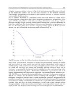
Figure 45 shows ingot density as a function of the raw material feed rate and power consumption in the plasma
consolidation of titanium. Plasma consolidation processes can reduce manufacturing costs for the preparation of titanium
VAR electrodes, which are usually plasma melted from pressed sponge or chip compacts.
Fig. 45 Relationship among raw materi
al feeding rate, ingot bulk density, and specific power consumption in
the plasma consolidation of titanium. Source: Ref 56.
With plasma consolidation, metal chlorides can be removed from titanium sponge to sufficiently low levels. Tungsten
carbide tool tips in titanium chips cannot be removed and eventually form high-density inclusions in the product.
Therefore, the conventional x-ray inspection of scrap is still necessary. Low-density inclusions such as titanium nitride
particles have not been found after plasma consolidation of contaminated titanium scrap and subsequent VAR remelting
(Ref 57). Plasma consolidation has also been successfully applied to the processing of titanium aluminide (TiAl), a low-
density alloy with excellent high-temperature service properties (Ref 57).
Plasma Arc Remelting. An electrode that has already been melted by a primary melting process such as electric arc or
induction melting can be plasma arc remelted into a water-cooled withdrawal crucible. The major objectives for plasma
arc remelting are:
• To obtain directional solidification without changing the chemical composition of the feed material
• To improve cleanliness by removal, size reduction, shape control, and redistribution of inclusions
• To lower gas impurity content
• To alloy with nitrogen
Plasma arc remelting is used most frequently in the Soviet Union to produce high-temperature alloys, bearing steels,
superalloys, and titanium alloys. Plasma arc remelting can be advantageous for the nitrogen alloying, deoxidation, or
desulfurization of nonreactive alloys. An example of successful reactive melting is the nitrogen alloying of steel during
plasma arc remelting with argon-nitrogen mixtures as the plasma gas (Ref 58). Figure 46 shows nitrogen concentrations
in various metals as a function of nitrogen partial pressure in the gaseous phase after plasma arc remelting. The data
indicate that excited molecules of nitrogen in the plasma react with the metal (Ref 58).
Fig. 46
Nitrogen concentrations in various metals as a function of the partial pressure of nitrogen after plasma
arc remelting. (a) Iron. (b) 16-25-
6 stainless steel. (c) Austenitic stainless steel. Curves A and B, induction
heating; minimum and maximum nitrogen concentrations, respectively.
Curve C, plasma arc remelting. Source:
Ref 58.
In plasma cold hearth melting, bars, sponge, or scrap can be continuously fed into a water-cooled copper trough,
usually called a hearth, and melted by means of plasma heat. The liquid metal flows over the lip of the hearth into a
withdrawal mold. The plasma cold hearth melting process is adapted from the electron beam cold hearth refining process,
which is a well-developed refining and casting method for superalloys. Plasma heat, instead of an electron beam, is
employed to minimize selective evaporative losses that occur during electron-beam melting in the pressure range of 0.01
to 1 Pa (10
-4
to 0.01 mbar, or 7.5 × 10
-5
to 0.0075 torr).
In the hearth, high-density inclusions from tungsten carbide tool tips will sink down to the skull. Low-density inclusions
can be dissociated or dissolved in the base metal during interaction with the superheated melt and the plasma jet.
Process optimization is necessary to prevent short circuiting of the hearth by unmelted particles and to establish sufficient
dwell time at high melting rates. The power distribution of one or more plasma torches required for smooth melting and
fluid flow can be ensured by automated torch-moving devices.
Figure 47 shows a pilot plasma cold hearth furnace (Fig. 47a) and the only industrial-scale plasma cold hearth melting
furnace currently in operation (Fig. 47b). The plasma heat source of the industrial furnace is unconventional in that there
is no mechanism provided for torch movement. The torches, called plasma electron beam guns, use hollow tantalum
cathodes and operate at pressures of 1 to 10 Pa (0.01 to 0.1 mbar, or 0.0075 to 0.075 torr). The unusually high specific
power consumption of this furnace reflects the relatively low efficiency of the heat source used.
Fig. 47 Two plasma cold hearth melting furnaces. (a) Pilot-
scale furnace with two tiltable plasma torches. Total
power: 400 kW. (b) ULVAC plasma beam furnace with six fixed plasma beam guns.
Total power: 2000 kW.
Source: Ref 57.
Figure 48 shows a modern plasma cold hearth melting furnace concept with a double-wall, water-cooled, vacuum-tight
furnace chamber and three plasma torches for the production of ingots 710 mm (28 in.) in diameter. Two torches serve the
hearth, and the third the ingot mold. The torches use hollow water-cooled copper electrodes. The high gas consumption of
this torch design means that an effective gas recycling system must be provided, especially if helium is used as the plasma
gas.
Fig. 48 Plasma cold hearth melting concept for the recycling of titanium scrap.
The operating principle of a gas-recycling system is shown in Fig. 49. Key technology in this system includes reactive
filters, oil-free high-capacity pump sets, and compressors. If necessary, the recycling system can be supplemented with
cleaning systems for oxygen, carbon dioxide, nitrogen, hydrogen, and moisture.
Fig. 49 Schematic of plasma gas-recycling system. 1, plasma furnace; 2, off-
gas heat exchanger; 3, cyclone
separator; 4, mechanical filter; 5, motor-actuated valve;
6, vacuum pump set; 7, chemical filter; 8, fine filter;
9, buffer; 10, compressor; 11, heat exchanger; 12, gas storage tank.
Plasma cold crucible casting is an alternative process to vacuum arc skull melting and casting or electron beam skull
melting and casting, and it can overcome some of the disadvantages of these processes. The disadvantages of vacuum arc
skull melting in the melting and casting of titanium and superalloys are:
• Control of superheating is not possible; increased power results in increased melting rate instead of superheating
• Expensive electrodes must be used instead of the high-
quality unconsolidated revert material that can be used for
plasma cold crucible casting
For small batches of superalloys (up to 8 kg, or 18 lb), electron beam skull casting is a well-established technique.
Electron beam melting and casting is rarely used for large castings of either superalloys or titanium alloys. This is because
of the shallow melt pool in the crucible due to lack of stirring action and the potential for selective evaporation of alloying
elements during melting.
Figure 50 shows a sectional view of an industrial-size plasma cold crucible casting furnace. The furnace consists of a
cylindrical, horizontally installed mold chamber with lockchambers at both sides and the melt chamber on top of the mold
chamber. A programmable torch-moving device is installed on top of the melt chamber.The pressure in the furnace during
the melting operation can be preselected; pressures typically range from 30 to 50 kPa (300 to 500 mbar, or 225 to 375
torr). The melting operation can be started at every pressure in this range. Solid material can be charged continuously into
the water-cooled copper crucible, and additional material can be fed into the crucible during melting. The melt is poured
into stationary molds or centrifugal casting molds situated in the mold chamber. The pouring stream can be superheated
during casting.