Volume 12 - Fractography Part 6 ppsx
Bạn đang xem bản rút gọn của tài liệu. Xem và tải ngay bản đầy đủ của tài liệu tại đây (2.61 MB, 60 trang )
Aug 1977, p 1587-1597
231.
W.M. Stobbs, Electron Microscopical Techniques for the Observation of Cavities, J. Microsc., Vol 116
, Pt.
1, May 1979, p 3-13
232.
R.J. Fields and M.F. Ashby, Observation on Wedge Cavities in the SEM, Scr. Metall.,
Vol 14 (No. 7), July
1980, p 791-796
233.
A.J. Perry. Cavitation in Creep, J. Mater. Sci., Vol 9, June 1974, p 1016-1039
234.
B.F. Dyson and D. McLean, A New Method of Predicting Creep Life, Met. Sci. J., Vol 6, 1972, p 220-223
235.
B. Walser and A. Rosselet, Determining the Remaining Life of Superheater-
Steam Tubes Which Have Been
in Service by Creep Tests and Structural Examinations, Sulzer Res., 1978, p 67-72
236.
N.G. Needham and T. Gladman, Nucleation and Growth of Creep Cavities in a Type 347 Steel, Met. Sci.,
Vol
14, Feb 1980, p 64-72
237.
Y. Lindblom, Refurbishing Superalloy Components for Gas Turbines, Mater. Sci. Technol., Vol 1,
Aug
1985, p 636-641
238.
J. Wortmann, Improving Reliability and Lifetime of Rejuvenated Turbine Blades, Mater, Sci. Technol.,
Vol
1, Aug 1985, p 644-650
239.
C.J. Bolton et al., Metallographic Methods of Determining Residual Creep Life, Mater. Sci. Eng.,
Vol 46,
Dec 1980, p 231-239
240.
R. Sandstrom and S. Modin, " The Residual Lifetime of Creep Deformed Components. Microstructural
Observations for Mo- and CrMo-Steels," Report IM-1348, Swedish Institute for Metals Research, 1979
241.
C. Bengtsson, "Metallographic Methods for Observation of Creep Cavities in Service Exposed Low-
Alloyed
Steel," Report IM-1636, Swedish Institute for Metals Research, March 1982
242.
J.F. Henry and F.V. Ellis, "Plastic Replication Techniques for Damage Assessment," Report RP2253-
01,
Electric Power Research Institute, Sept 1983
243.
J.F. Henry, Field Metallography. The Applied Techniques of In-Place Analysis, in
Corrosion,
Microstructure, & Metallography, Vol 12, Microstructural Science,
American Society for Metals and the
International Metallographic Society, 1985, p 537-549
244.
M.C. Murphy and G.D. Branch, Metallurgical Changes in 2.25 CrMo Steels During Creep-Rupture Test,
J.
Iron Steel Inst., Vol 209, July 1971, p 546-561
245.
J.M. Leitnaker and J. Bentley, Precipitate Phases in Type 321 Stainless Steel After Aging 17 Years at
600
°C, Metall. Trans., Vol 8A, Oct 1977, p 1605-1613
246.
M. McLean, Microstructural Instabilities in Metallurgical Systems A Review, Met. Sci.,
Vol 12, March
1978, p 113-122
247.
S. Kihara et al.,
Morphological Changes of Carbides During Creep and Their Effects on the Creep Properties
of Inconel 617 at 1000 °C, Metall, Trans., Vol 11A, June 1980, p 1019-1031
248.
S.F. Claeys and J.W. Jones, Role of Microstructural Instability in Long Time Creep Life Prediction,
Met.
Sci., Vol 18, Sept 1984, p 432-438
249.
Y. Minami et al., Microstructural Changes in Austenitic Stainless Steels During Long-Term Aging,
Mater.
Sci. Technol., Vol 2, Aug 1986, p 795-806
250.
J.R. Low, Jr., Impurities, Interfaces and Brittle Fracture, Trans. AIME, Vol 245, Dec 1969, p 2481-2494
251.
W.P. Rees and B.E. Hopkins, Intergranular Brittleness in Iron-Oxygen Alloys, J. Iron Steel Inst.,
Vol 172,
Dec 1952, p 403-409
252.
J.R. Low, Jr. and R.G. Feustel, Inter-Crystalline Fracture and Twinning of Iron at Low Temperatures,
Acta
Metall., Vol 1, March 1953, p 185-192
253.
B.E. Hopkins and H.R. Tipler, Effect of Heat-Treatment on the Brittleness of High-Purity Iron-
Nitrogen
Alloys, J. Iron Steel Inst., Vol 177, May 1954, p 110-117
254.
B.E. Hopkins and H.R. Tipler, The Effect of Phosphorus on the Tensile and Notch-
Impact Properties of
High-Purity Iron and Iron-Carbon Alloys. J. Iron Steel Inst., Vol 188, March 1958, p 218-237
255.
A.R. Troiano, The Role of Hydrogen and Other Interstitials in the Mechanical Behavior of Metals,
Trans.
ASM, Vol 52, 1960, p 54-80
256.
C. Pichard et al., The Influence of Oxygen and Sulfur on the Intergranular Brittleness of Iron, Metall. Trans.,
Vol 7A, Dec 1976, p 1811-1815
257.
M.C. Inman and H.R. Tipler, Grain-Boundary Segregation of Phosphorus in an Iron-
Phosphorus Alloy and
the Effect Upon Mechanical Properties. Acta Metall., Vol 6, Feb 1958, p 73-84
258.
G.T. Hahn et al., "The Effects of Solutes on the Ductile-to-Brittle Transition in Refra
ctory Metals," DMIC
Memorandum 155, Battelle Memorial Institute, 28 June 1962
259.
R.E. Maringer and A.D. Schwope, On the Effects of Oxygen on Molybdenum, Trans. AIME,
Vol 200, March
1954, p 365-366
260.
T.G. Nieh and W.D. Nix, Embrittlement of Copper Du
e to Segregation of Oxygen to Grain Boundaries,
Metall. Trans., Vol 12A, May 1981, p 893-901
261.
R.H. Bricknell and D.A. Woodford, The Embrittlement of Nickel Following High Temperature Air
Exposure, Metall. Trans., Vol 12A, March 1981, p 425-433
262.
K.M. Olsen et al., Embrittlement of High Purity Nickel, Trans. ASM, Vol 53, 1961, p 349-358
263.
S. Floreen and J.H. Westbrook, Grain Boundary Segregation and the Grain Size Dependence of Strength of
Nickel-Sulfur Alloys, Acta Metall., Vol 17, Sept 1969, p 1175-1181
264.
W.C. Johnson et al., Confirmation of Sulfur Embrittlement in Nickel Alloys, Scr. Metall.,
Vol 8, Aug 1974,
p 971-974
265.
C. Loier and J.Y. Boos, The Influence of Grain Boundary Sulfur Concentration on the Intergranular
Brittleness of Nickel of Different Purities, Metall. Trans., Vol 12A, July 1981, p 1223-1233
266.
J.H. Westbrook and D.L. Wood, A Source of Grain Boundary Embrittlement in Intermetallics, J. Inst. Met.,
Vol 91, 1962-1963, p 174-182
267.
E. Voce and A.P.C. Hallowes, The Mechanism of the Embrittlement of Deoxidized Copper by Bismuth,
J.
Inst. Met., Vol 73, 1947, p 323-376
268.
T.H. Schofield and F.W. Cuckow, The Microstructure of Wrought Non-Arsenical Phosphorus-
Deoxidized
Copper Containing Small Quantities of Bismuth, J. Inst. Met., Vol 73, 1947, p 377-384
269.
L.E. Samuels, The Metallography of Copper Containing Small Amounts of Bismuth, J. Inst. Met.,
Vol 76,
1949-1950, p 91-102
270.
C.W. Spencer et al., Bismuth in Copper Grain Boundaries, Trans. AIME, Vol 209, June 1957, p 793-794
271.
D. McLean and L. Northcott, Antimonial 70:30 Brass, J. Inst. Met., Vol 72, 1946 p 583-616
272.
D. McLean, The Embrittlement of Copper: Antimony Alloys at Low Temperatures, J. Inst. Met.,
Vol 81,
1952-1953 p 121-123
273.
R. Carlsson, Hot Embrittlement of Copper and Brass Alloys, Scand. J. Metall., Vol 9 (No. 1), 1980, p 25-29
274.
H.K. Ihrig, The Effect of Various Elements on the Hot-Workability of Steel, Trans. AIME,
Vol 167, 1946, p
749-790
275.
J.M. Middletown and H.J. Protheroe, The Hot-Tearing of Steel, J. Iron Steel Inst.,
Vol 168, Aug 1951, p
384-400
276.
C.T. Anderson et al., Effect of Various Elements on Hot-
Working Characteristics and Physical Properties of
Fe-C Alloys, J. Met., Vol 5, April 1953, p 525-529
277.
C.T. Anderson et al., Forgeability of Steels with Varying Amounts of Manganese and Sulfur. Trans. AIME,
Vol 200, July 1954, p 835-837
278.
D. Smith et al., Effects of Composition on the Hot Workability of Resulphurized Free-Cutting Steels,
J. Iron
Steel Inst., Vol 210, June 1972, p 412-421
279.
W.J. McG. Tegart and A. Gittins, The Role of Sulfides in the Hot Workability of Steels, in
Sulfide Inclusions
in Steel, American Society for Metals, 1975, p 198-211
280.
A. Josefsson et al., The Influence of Sulphur and Oxygen in Causing Red-Shortness in Steel,
J. Iron Steel
Inst., Vol 191, March 1959, p 240-250
281.
P. Bjornson and H. Nathorst, A Special Type of Ingot Cracks Caused by Certain Impurities,
Jernkontorets
Ann., Vol 139, 1955, p 412-438
282.
W.J.M. Salter, Effec
t of Mutual Additions of Tin and Nickel on the Solubility and Surface Energy of Copper
in Mild Steel, J. Iron Steel Inst., Vol 207, Dec 1969, p 1619-1623
283.
W.J. Jackson and D.M. Southall, Effect of Copper and Tin Residual Amounts on the Mechanical Prop
erties
of 1.5Mn-Mo Cast Steel, Met. Technol., Vol 5, Pt. 11, Nov 1978, p 381-390
284.
K. Born, Surface Defects in the Hot Working of Steel, Resulting from Residual Copper and Tin, Stahl Eisen,
Vol 73 (No. 20), BISI 3255, 1953, p 1268-1277
285.
I.S. Brammar et al.,
The Relation Between Intergranular Fracture and Sulphide Precipitation in Cast Alloy
Steels, in ISI 64, Iron and Steel Institute, 1959, p 187-208
286.
D. Bhattacharya and D.T. Quinto, Mechanism of Hot-Shortness in Leaded and Tellurized Free-Mac
hining
Steels, Metall. Trans., Vol 11A, June 1980, p 919-934
287.
R.A. Perkins and W.O. Binder, Improving Hot-Ductility of 310 Stainless, J. Met.,
Vol 9, Feb 1957, p
239-245
288.
L.G. Ljungström, The Influence of Trace Elements on the Hot Ductility of Austenitic 17Cr13NiMo-
Steel,
Scand. J. Metall., Vol 6, 1977, p 176-184
289.
W.B. Kent, Trace-Element Effects in Vacuum-Melted Superalloys, J. Vac. Sci. Technol.,
Vol 11, Nov/Dec
1974, p 1038-1046
290.
R.T. Holt and W. Wallace, Impurities and Trace Elements in Nickel-Base Superalloys, Int. Met. Rev.,
Vol
21, March 1976, p 1-24
291.
A.R. Knott and C.H. Symonds, Compositional and Structural Aspects of Processing Nickel-
Base Alloys,
Met. Technol., Vol 3, Aug 1976, p 370-379
292.
C.H. Lorig and A.R. Elsea, Occurrence of Intergranular Fracture in Cast Steels, Trans. AFS,
Vol 55, 1947, p
160-174
293.
B.C. Woodfine, "First Report on Intergranular Fracture in Steel Castings," BSCRA Report 38/54/FRP.5,
British Steel Casting Research Association, March 1954
294.
B.C. Woodfine, Effect of Al and N on the Occurrence of Intergranular Fracture in Steel Castings,
J. Iron
Steel Inst., Vol 195, Aug 1960, p 409-414
295.
R.F. Harris and G.D. Chandley, High Strength Steel Castings. Aluminum Nitride Embrittlement, Mod Cast.,
March 1962, p 97-103
296.
J.A. Wright and A.G. Quarrell, Effect of Chemical Composition on the Occurrence of Intergranular Fracture
in Plain Carbon Steel Castings Containing Aluminum and Nitrogen, J. Iron Steel Inst.,
Vol 200, April 1962,
p 299-307
297.
N.H. Croft et al., Intergranular Fracture of Steel Castings. in
Advances in the Physical Metallurgy and
Applications of Steels, Publication 284, The Metals Society, 1982, p 286-295
298.
E. Colombo and B. Cesari, The Study of the Influence of Al and N on th
e Susceptibility to Crack Formation
of Medium Carbon Steel Ingots, Metall. Ital., Vol 59 (No. 2), 1967, p 71-75
299.
S.C. Desai, Longitudinal Panel Cracking in Ingots, J. Iron Steel Inst., Vol 191, March 1959, p 250-256
300.
R. Sussman et al., Occurrence
and Control of Panel Cracking in Aluminum Containing Steel Heats, in
Mechanical Working & Steel Processing,
Meeting XVII, American Institute of Mining, Metallurgical, and
Petroleum Engineers, 1979, p 49-78
301.
L. Ericson, Cracking in Low Alloy Aluminum Grain Refined Steels, Scand. J. Metall.,
Vol 6, 1977, p
116-124
302.
F. Vodopivec, Influence of Precipitation and Precipitates of Aluminum Nitride on Torsional Deformability
of Low-carbon Steel, Met. Technol., Vol 5, April 1978, p 118-121
303.
G.D. Funnell and R.J. Davies, Effect of Aluminum Nitride Particles on Hot Ductility of Steel, Met. Technol.,
Vol 5, May 1978, p 150-153
304.
T. Lepistö and P. Kettunen, Embrittlement Caused by ε-Martensite in Stainless Steels, Scand. J. Metall.,
Vol
7, 1978, p 71-76
305.
F.W. Schaller and V.F. Zackay, Low Temperature Embrittlement of Austenitic Cr-Mn-N-Fe Alloys,
Trans.
ASM, Vol 51, 1959, p 609-628
306.
D. Hennessy et al., Phase Transformation of Stainless Steel During Fatigue, Metall. Trans.,
Vol 7A, March
1976, p 415-424
307.
H.H. Bleakney, The Creep-Rupture Embrittlement of Metals as Exemplified by Aluminum, Can. Metall. Q.,
Vol 2 (No. 3), 1963, p 391-315
308.
D.E. Ferrell and A.W. Pense, Creep Embrittlement of 2-
1
4
% Cr-1% Mo Steel, in Re
port to Materials
Division, Pressure Vessel Research Council, May 1973
309.
H.R. Tipler, "The Role of Trace Elements in Creep Embrittlement and Cavitation of Cr-Mo-
V Steels,"
National Physical Laboratory, 1972
310.
R. Bruscato, Temper Embrittlement and Creep Embrittlement of 2-
1
4
Cr-
1Mo Shielded Metal Arc Weld
Deposits, Weld, J., Vol 49, April 1970, p 148s-156s
311.
R.A. Swift and H.C. Rogers, Study of Creep Embrittlement of 2-
1
4
Cr-1Mo Steel Weld Metal, Weld. J.,
Vol
55, July 1976, p 188s-198s
312.
R.A. Swift, The Mechanism of Creep Embrittlement in 2-
1
4
Cr-1Mo Steel, in 2-
1
4
Chrome-
1 Molybdenum
Steel in Pressure Vessels and Piping, American Society of Mechanical Engineers, 1971
313.
L.K.L. Tu and B.B. Seth, Effect of Composition, Strength, and Residual Elements on Toughness and Creep
Properties of Cr-Mo-V Turbine Rotors, Met. Technol., Vol 5, March 1978, p 79-91
314.
S.H. Chen et al., The Effect of Trace Impurities on the Ductility of a Cr-Mo-
V Steel at Elevated
Temperatures, Metall. Trans., Vol 14A, April 1983, p 571-580
315.
M.P. Seah, Impurities, Segregation and Creep Embrittlement, Philos. Trans. R. Soc. (London) A,
Vol 295,
1980, p 265-278
316.
H.J. Kerr and F. Eberle, Graphitization of Low-Carbon and Low-Carbon-Molybdenum Steels, Trans. ASME,
Vol 67, 1945, p 1-46
317.
S.L. Hoyt et al., Summary Report on the Joint E.E.I-
A.E.I.C. Investigation of Graphitization of Piping,
Trans. ASME, Aug 1946, p 571-580
318.
R.W. Emerson and M. Morrow, Further Observations of Graphitization in Aluminum-
Killed
Carbon-Molybdenum Steel Steel Steam Piping, Trans. AIME, Aug 1946, p 597-607
319.
J.G. Wilson, Graphitization of Steel in Petroleum Refining Equipment, Weld. Res. Counc. Bull.,
No. 32, Jan
1957, p 1-10
320.
A.B. Wilder et al., Stability of AISI Alloy Steels, Trans. AIME, Vol 209, Oct 1957, p 1176-1181
321.
I.M. Bernstein and A.W. Thompson, Ed., Hydrogen in Metals, American Society for Metals, 1974
322.
C.D. Beachem, Ed., Hydrogen Damage, American Society for Metals, 1977
323.
R.W. Staehle et al., Ed., Stress Corrosion Cracking and Hydrogen Embrittlement in Iron Base Alloys,
NACE
Reference Book 5, National Association of Corrosion Engineers, 1977
324.
A.E. Schuetz and W.D. Robertson, Hydrogen Absorption, Embrittlement and Fracture of Steel, Corrosion,
Vol 13, July 1957, p 437t-458t
325.
I.M. Bernstein, The Role of Hydrogen in the Embrittlement of Iron and Steel, Mater. Sci. Eng.,
Vol 6, July
1970, p 1-19
326.
M.R. Louthan, Jr. et al., Hydrogen Embrittlement of Metals, Mater, Sci. Eng., Vol 10, 1972, p 357-368
327.
I.M. Bernstein and A.W. Thompson, Effect of Metallurgical Variables on Environmental Fracture of Steels,
Int. Met. Rev., Vol 21, Dec 1976, p 269-287
328.
J.P. Hirth, Effects of Hydrogen on the Properties of Iron and Steel, Metall. Trans.,
Vol 11A, June 1980, p
861-890
329.
I.M. Bernstein et al., Effect of Dissolved Hydrogen on Mechanical Behavior of Metals, in
Effect of Hydrogen
on Behavior of Materials, Ameri
can Institute of Mining, Metallurgical, and Petroleum Engineers, 1976, p
37-58
330.
L.H. Keys, The Effects of Hydrogen on the Mechanical Behavior of Metals, Met. Forum,
Vol 2 (No. 3),
1979, p 164-173
331.
S.P. Lynch, Mechanisms of Hydrogen-Assisted Cracking, Met. Forum, Vol 2 (No. 3), 1979, p 189-200
332.
H.G. Nelson, Hydrogen Embrittlement, in Embrittlement of Engineering Alloys,
Academic Press, 1983, p
275-359
333.
C.A. Zapffe, Hydrogen Flakes and Shatter Cracks, Metals and Alloys, Vol 11, May 1940, p 145-
151; June
1940, p 177-184; Vol 12, July 1940, p 44-51; Aug 1940, p 145-148
334.
C.A. Zapffe, Defects in Cast and Wrought Steel Caused by Hydrogen, Met. Prog.,
Vol 42, Dec 1942, p
1051-1056
335.
E.R. Johnson et al., Flaking in Alloy Steels, in Open Hearth Conference, 1944, p 358-377
336.
A.W. Dana et al., Relation of Flake Formation in Steel to Hydrogen, Microstructure, and Stress,
Trans.
AIME, Vol 203, Aug 1955, p 895-905
337.
J.D. Hobson, The Removal of Hydrogen by Diffusion from Large Masses of Steel, J. Iron Steel Inst.,
Vol
191, April 1959, p 342-352
338.
J.M. Hodge et al., Effect of Hydrogen Content on Susceptibility to Flaking, Trans. AIME,
Vol 230. 1964, p
1182-1193
339.
J.E. Ryall et al., The Effect of Hydrogen in Rolled Steel Products, Met. Forum,
Vol 2 (No. 3), 1979, p
174-182
340.
R.E. Cramer and E.C. Bast, The Prevention of Flakes by Holding Railroad Rails at Various Constant
Temperatures, Trans. ASM, Vol 27, 1939, p 923-934
341.
F. Terasaki and S. Okamoto, Fractography of Hydrogen-Embrittled Steels, Tetsu-to-
Hagané (J. Iron Steel
Inst. Jpn.), Vol 60, 1974, p S576 (HB 9225)
342.
A.P. Coldren and G. Tither, Metallographic Study of Hydrogen-Induced Cracking in Line Pipe Steel, J. Met.,
Vol 28, May 1976, p 5-10
343.
M.R. Louthan, Jr. an
d R.P. McNitt, The Role of Test Technique in Evaluating Hydrogen Embrittlement
Mechanisms, in Effects of Hydrogen on Behavior of Materials,
American Institute of Mining, Metallurgical,
and Petroleum Engineers, 1976, p 496-506
344.
C.L. Briant et al., Embr
ittlement of a 5 Pct. Nickel High Strength Steel by Impurities and Their Effects on
Hydrogen-Induced Cracking, Metall. Trans., Vol 9A, May 1978, p 625-633
345.
D. Hardie and T.I. Murray, Effect of Hydrogen on Ductility of a High Strength Steel in Hardened
and
Tempered Conditions, Met. Technol., Vol 5, May 1978, p 145-149
346.
T.A. Adler et al., Metallographic Studies of Hydrogen-Induced Crack Growth in A-
106 Steel, in
Microstructural Science, Vol 8, Elsevier, 1980, p 217-230
347.
J.E. Costa and A.W. Thom
pson, Effect of Hydrogen on Fracture Behavior of a Quenched and Tempered
Medium-Carbon Steel, Metall. Trans., Vol 12A, May 1981, p 761-771
348.
B.D. Craig, A Fracture Topographical Feature Characteristic of Hydrogen Embrittlement, Corrosion,
Vol
37, Sept 1981, p 530-532
349.
R. Garber et al., Hydrogen Assisted Ductile Fracture of Spheriodized Carbon Steels, Metall. Trans.,
Vol
12A, Feb 1981, p 225-234
350.
H. Cialone and R.J. Asaro, Hydrogen Assisted Ductile Fracture of Spheroidized Plain Carbon Steels,
Metall.
Trans., Vol 12A, Aug 1981, p 1373-1387
351.
T. Boniszewski and J. Moreton, Effect of Micro-
Voids and Manganese Sulphide Inclusion in Steel on
Hydrogen Evolution and Embrittlement, Br. Weld. J., Vol 14, June 1967, p 321-336
352.
P.H. Pumphrey, Effect of Sulphide Inclusions on Hydrogen Diffusion in Steels, Met. Sci.,
Vol 16, Jan 1982,
p 41-47
353.
K. Farrell and A.G. Quarrell, Hydrogen Embrittlement of an Ultra-High-Tensile Steel, J. Iron Steel Inst.,
Vol
202, Dec 1964, p 1002-1011
354.
A. Ciszewski et al.,
Effect of Nonmetallic Inclusions on the Formation of Microcracks in Hydrogen Charged
1% Cr Steel, in Stress Corrosion Cracking and Hydrogen Embrittlement of Iron Base Alloys,
NACE
Reference Book 5, National Association of Corrosion Engineers, 1977, p 671-679
355.
G.M. Presouyre and C. Zmudzinski, Influence of Inclusions on Hydrogen Embrittlement, in
Mechanical
Working & Steel Processing,
Meeting XVIII, American Institute of Mining, Metallurgical, and Petroleum
Engineers, 1980, p 534-553
356.
R.L. Cowan II and C.S. Tedmon, Jr., Intergranular Corrosion of Iron-Nickel-Chromium Alloys, in
Advances
in Corrosion Science and Technology, Vol 3, Plenum Press, 1973, p 293-400
357.
E.M. Mahla and N.A. Nielson, Carbide Precipitation in Type 304 Stainless Steel
An Electron Microscope
Study, Trans. ASM, Vol 43, 1951, p 290-322
358.
R. Stickler and A. Vinckier, Morphology of Grain-
Boundary Carbides and its Influence on Intergranular
Corrosion of 304 Stainless Steel, Trans. ASM, Vol 54, 1961, p 362-380
359.
R. Stickler and A. Vinckier, Precipitation of Chromium Carbide on Grain Boundaries in a 302 Austenitic
Stainless Steel, Trans. AIME, Vol 224, Oct 1962, p 1021-1024
360.
K.T. Aust et al., Intergranular Corrosion and Electron Microscopic Studies of Austenit
ic Stainless Steels,
Trans. ASM, Vol 60, 1967, p 360-372
361.
S. Danyluk et al.,
Intergranular Fracture, Corrosion Susceptibility, and Impurity Segregation in Sensitized
Type 304 Stainless Steel, J. Mater. Energy Syst., Vol 7, June 1985, p 6-15
362.
A.P. Bond and E.A. Lizlovs, Intergranular Corrosion of Ferritic Stainless Steels, J. Electrochem. Soc.,
Vol
116, Sept 1969, p 1305-1311
363.
A.P. Bond, Mechanisms of Intergranular Corrosion in Ferritic Stainless Steels, Trans. AIME,
Vol 245, Oct
1969, p 2127-2134
364.
E.L. Hall and C.L. Briant, Chromium Depletion in the Vicinity of Carbides in Sensitized Austenitic Stainless
Steels, Metall. Trans., Vol 15A, May 1984, p 793-811
365.
J.B. Lee et al., An Analytical Electron Microscope Examination of Sensitized
AISI 430 Stainless Steel,
Corrosion, Vol 41, Feb 1985, p 76-80
366.
E.P. Butler and M.G. Burke, Chromium Depletion and Martensite Formation at Grain Boundaries in
Sensitized Austenitic Stainless Steel, Acta Metall., Vol 34 March 1986, p 557-570
367.
M.A. Streicher, Screening Stainless Steels from the 240-
Hr Nitric Acid Test by Electrolytic Etching in
Oxalic Acid, ASTM Bull., No. 188, Feb 1953, p 35-38; July 1953, p 58-59
368.
M.A. Streicher, Theory and Application of Evaluation Tests for Detecting Suscep
tibility to Intergranular
Attack in Stainless Steels and Related Alloys Problems and Opportunities, in
Intergranular Corrosion of
Stainless Alloys, STP 656, American Society for Testing and Materials, p 3-84
369.
A.P. Majidi and M.A. Streicher, "The Effe
ct of Methods of Cutting and Grinding on Sensitization in Surface
Layers in Type 304 Stainless Steel," Paper 25, presented at Corrosion/83, National Association of Corrosion
Engineers, 1983
370.
J.M. Schluter and J.A. Chivinsky, Surface Preparation Requirements for ASTM A262, in
Laboratory
Corrosion Tests and Standards, STP 866, American Society for Testing and Materials, 1985, p 455-464
371.
W. Rostoker et al., Embrittlement by Liquid Metals, Reinhold, 1960
372.
N.S. Stoloff, Liquid Metal Embrittlement, in Surfaces and Interfaces, Pt.
II, Syracuse University Press, 1968,
p 157-182
373.
A.R.C. Westwood et al., Adsorption Induced Brittle Fracture in Liquid-Metal Environments,
in Fracture,
Vol III, Academic Press, 1971, p 589-644
374.
M.H. Kamdar, Embrittlement by Liquid Metals, Prog. Mater. Sci., Vol 15, Pt. 4, 1973, p 289-374
375.
M.H. Kamdar, Liquid Metal Embrittlement, in Embrittlement of Engineering Alloys,
Academic Press, 1983,
p 361-459
376.
M.H. Kamdar, Ed., Embrittlement by Liquid and Solid Metals,
American Institute of Mining, Metallurgical,
and Petroleum Engineers, 1984
377.
M.B. Reynolds, Radiation Effects in Some Engineering Alloys, J. Mater., Vol 1, March 1966, p 127-152
378.
K. Ohmae and T.O. Ziebold, The Influence of Impurity Content on
the Radiation Sensitivity of Pressure
Vessel Steels Use of Electron Microprobe for Irregular Surfaces, J. Nucl. Mater., Vol 43, 1972, p 245-257
379.
J.R. Hawthorne and L.E. Steele, Metallurgical Variables as Possible Factors Controlling Irradiation
Response of Structural Steels, in The Effects of Radiation on Structural Metals,
STP 426, American Society
for Testing and Materials, 1967, p 534-572
380.
Irradiation Effects on the Microstructure and Properties of Metals, STP 611, American Society for Testing
and Materials, 1976
381.
J.O. Stiegler and E.E. Bloom, The Effects of Large Fast-
Neutron Fluences on the Structure of Stainless Steel,
J. Nucl. Mater., Vol 33, 1969, p 173-185
382.
S.D. Harkness and C.Y. Li, A Study of Void Formation in Fast Neutron-Irradiated Metals, Metall. Trans.,
Vol 2, May 1971, p 1457-1470
383.
H.R. Brager et al., Irradiation-Produced Defects in Austenitic Stainless Steel, Metall. Trans.,
Vol 2, July
1971, p 1893-1904
384.
H.R. Brager and J.L. Straalsund, Defect Development in Neutron Irradiated Type 316 Stainless Steel,
J.
Nucl. Mater., Vol 46, 1973, p 134-158
385.
K. Farrell and R.T. King, Radiation-Induced Strengthening and Embrittlement in Aluminum, Metall. Trans.,
Vol 4, May 1973, p 1223-1231
386.
J.R. Strohm and W.E. Jominy, High Forging Temperatures Revealed by Facets in Fracture Tests,
Trans.
ASM, Vol 36, 1946, p 543-571
387.
A. Preece et al., The Overheating and Burning of Steel, J. Iron Steel Inst., Vol 153, Pt. 1, 1946, p 237p-254p
388.
A. Preece and J. Nutting, The Detection of Overheating and Burning in Steel by Microscopical Methods,
J.
Iron Steel Inst., Vol 164, Jan 1960, p 46-50
389.
B.J. Schulz and C.J. McMahon, Fracture of Alloy Steels by Intergranular Microvoid Coalescence as
Influenced by Composition and Heat Treatment, Metall. Trans., Vol 4, Oct 1973, p 2485-2489
390.
J.A. Disario, "Overheating and Its Effect on the Toughness of ASTM A508 Class II Forgings," MS thesis,
Lehigh University, 1973
391.
T.J. Baker and R. Johnson, Overheating and Fracture Toughness, J. Iron Steel Inst.,
Vol 211, Nov 1973, p
783-791
392.
T.J. Baker, Use of Scanning Electron Microscopy in Studying Sulphide Morphology on Fracture Surfaces, in
Sulfide Inclusions in Steel, American Society for Metals, 1975, p 135-158
393.
G.E. Hale and J. Nutting, Overheating of Low-Alloy Steels, Int. Met. Rev., Vol 29 (No. 4), 1984, p 273-298
394.
R.C. Andrew et al., Overheating in Low-Sulphur Steels, J. Austral. Inst. Met., Vol 21, June-
Sept 1976, p
126-131
395.
R.C. Andrew and G.M. Weston, the Effect of Overheating on the Toughness of Low Sulphur ESR Steels,
J.
Austral. Inst. Met., Vol 22, Sept-Dec 1977, p 171-176
396.
S. Preston et al., Overheating Behavior of a Grain-Refined Low-Sulphur Steel, Mater. Sci. Technol.,
Vol 1,
March 1985, p 192-197
397.
A.L. Tsou et al., The Quench-Aging of Iron, J. Iron Steel Inst., Vol 172, Oct 1952, p 163-171
398.
T.C. Lindley and C.E. Richards, The Effect of Quench-Aging on the Cleavage Fracture of a Low-
Carbon
Steel, Met. Sci. J., Vol 4, May 1970, p 81-84
399.
A.S. Keh and W.C. Leslie, Recent Observations on Quench-
Aging and Strain Aging of Iron and Steel, in
Materials Science Research, Vol 1, Plenum Press, 1963, p 208-250
400.
E.R. Morgan and J.F. Enrietto, Aging in Steels, in AISI 1963 Regional Technical Meeting,
American Iron
and Steel Institute, 1964, p 227-252
401.
W.C. Leslie and A.S. Keh, Aging of Flat-
Rolled Steel Products as Investigated by Electron Microscopy, in
Mechanical Working of Steel, Pt. II. Gordon & Breach, 1965, p 337-377
402.
E. Stolte and W. Heller, The State of Knowledge of the Aging of Steels, I. Fundamental Principles,
Stahl
Eisen, Vol 90 (No. 16), BISI 8920, 1970, p 861-868
403.
L.R. Shoenberger and E.J. Paliwoda, Accelerated Strain Aging of Commercial Sheet Steels, Trans. ASM,
Vol 45, 1953, p 344-361
404.
F. Garofalo and G.V. Smith, The Effect of Time and Temperature on Various Mechanical Properties During
Strain Aging of Normalized Low Carbon Steels, Trans. ASM, Vol 47, 1955, p 957-983
405.
J.D. Baird, Strain Aging of Steel A Critical Review, Iron Steel, Vol 36, May 1963, p 186-
192; June 1963, p
326-334; July 1963, p 368-374; Aug 1963, p 400-405; Sept 1963, p 450-457
406.
J.D. Baird, The Effects of Strain-
Aging Due to Interstitial Solutes on the Mechanical Properties of Metals,
Metall. Rev., Vol 16, Feb 1971, p 1-18
407.
G.F. Vander Voort, Failures of Tools and Dies, in Failure Analysis and Prevention, Vol 11, 9th ed.,
Metals
Handbook, American Society for Metals, 1986, p 563-585
408.
L.D. Jaffee and J.R. Hollomon, Hardenability and Quench Cracking, Trans. AIME, Vol 167, 1946, p 617-626
409.
M.C. Udy and M.K. Barnett, A Laboratory Study of Quench Cracking in Cast Alloy Steels, Trans. ASM,
Vol
38, 1947, p 471-487
410.
J.W. Spretnak and C. Wells, An Engineering Analysis of the Problem of Quench Cracking in Steel,
Trans.
ASM, Vol 42, 1950, p 233-269
411.
C. Wells, Quench Cracks in Wrought Steel Tubes, Met. Prog., Vol 65, May 1954, p 113-121
412.
T. Kunitake and S. Sugisawa, The Quench-Cracking Susceptibility of Steel, Sumitomo Search,
No. 5, May
1971, p 16-25
413.
K.E. Thelning, Why Does Steel Crack on Hardening, Härt Tech Mitt., Vol 4, BISI 12602, 1970, p 271-281
414.
P. Gordon, The Temper Colors on Steel, J. Heat Treat., Vol 1, June 1979, p 93
415.
Modern Steels, 6th ed., Bethlehem Steel Corporation, 1967, p 149
416.
D.J. McAdam and G.W. Geil, Rate of Oxidation of Steels as Determined From Interference Colors of Oxide
Films, J. Res. NBS, Vol 23, July 1939, p 63-124
417.
A.J. Lena, Effect of Sigma Phase on Properties of Alloys, Met. Prog., Vol 66, Aug 1954, p 94-99
418.
J.I. Morley and H.W. Krikby, Sigma-Phase Embrittlement in 25Cr-20Ni Heat-Resisting Steels,
J. Iron Steel
Inst., Vol 172, Oct 1952, p 129-142
419.
A.M. Talbot and D.E. Furman, Sigma Formation and Its Effect
on the Impact Properties of
Iron-Nickel-Chromium Alloys, Trans. ASM, Vol 45, 1953, p 429-442
420.
E.O. Hall and S.H. Algie, The Sigma Phase, Met. Rev., Vol 11, 1966, p 61-88
421.
G. Matern et al., The Formation of Sigma Phase in Austenitic Ferrite Stain
less Steels and Its Influence on
Mechanical Properties, Mem. Sci. Rev. Met., BISI 13972, 1974, p 841-851
422.
W.J. Boesch and J.S. Slaney, Preventing Sigma Phase Embrittlement in Nickel Base Superalloys,
Met.
Prog., Vol 86, July 1964, p 109-111
423.
J.R. Mihalisin et al., Sigma Its Occurrence, Effect, and Control in Nickel-Base Superalloys, Trans. AIME,
Vol 242, Dec 1968, p 2399-2414
424.
H.L. Logan, The Stress Corrosion of Metals, John Wiley & Sons, 1966
425.
V.V. Romanov, Stress-Corrosion Cracking of Metals,
Israel Program for Scientific Translations and the
National Science Foundation, 1961
426.
H.L. Craig, Jr., Ed., Stress Corrosion New Approaches,
STP 610, American Society for Testing and
Materials, 1976
427.
R.W. Staehle et al., Ed., Fundamental Aspects of Stress Corrosion Cracking,
National Association of
Corrosion Engineers, 1969
428.
C. Edeleanu, Transgranular Stress Corrosion in Chromium-Nickel Stainless Steels, J. Iron Steel Inst.,
Vol
173, Feb 1953, p 140-146
429.
N.A. Neilsen Environmental Effects on Fracture Morphology, in Electron Fractography,
STP 436,
American Society for Testing and Materials, 1968, p 124-150
430.
J.C. Scully, Scanning Electron Microscope Studies of Stress-Corrosion Cracking, in
Scanning Electron
Microscopy, IIT Research Institute, 1970, p 313-320
431.
J.C. Scully, Failure Analysis of Stress Corrosion Cracking with the Scanning Electron Microscope, in
Scanning Electron Microscopy, Pt. IV, IIT Research Institute, 1974, p 867-874
432.
B. Poulson, The Fractography of Stress Corrosion Cracking in Carbon Steels, Corros, Sci.,
Vol 15, Sept
1975, p 469-477
433.
H. Okada et al.,
Scanning Electron Microscope Observation of Fracture Faces of Austenitic Stainless Steels
by Stress Corrosion Cracking, Nippon Kinzoku Gakkai-shi, Vol 37, 1973, p 197-203
434.
Y. Mukai et al., Fractographic Observation of Stress-
Corrosion Cracking of AISI 304 Stainless Steel in
Boiling 42 Percent Magnesium-Chloride Solution, in Fractography in Failure Analysis,
STP 645, American
Society for Testing and Materials, 1978, p 164-175
435.
B.C. Woodfine, Temper-Brittleness: A Critical Review of the Literature, J. Iron Steel Inst.,
Vol 173, March
1953, p 229-240
436.
J.R. Low, Jr., Temper Brittleness A Review of Recent Work, in Fracture of Engineering Materials,
American Society for Metals, 1964, p 127-142
437.
C.J. McMahon, Jr., Temper Brittleness An Interpretive Review, in Temper Embrittlement in Steel,
STP 407,
American Society for Testing and Materials, 1968, p 127-167
438.
I. Olefjord, Temper Embrittlement, Int. Met. Rev., Vol 23 (No. 4), 1978, p 149-163
439.
R.G.C. Hill and J.W. Martin, A Fractographic Study of Some Temper Brittle Steels, Met. Treat. Drop Forg.,
Vol 29, Aug 1962, p 301-310
440.
H. Ohtani and C.J. McMahon, Jr., Modes of Fracture in Temper Embrittled Steels, Acta Metall.,
Vol 23,
March 1975, p 377-386
441.
J. Yu and C.J. McMahon, Jr., Variation of the Fracture Mode in Temper Embrittled 2.25Cr-
1Mo Steel,
Metall. Trans., Vol 16A, July 1985, p 1325-1331
442.
J.B. Cohen et al., A Metallographic Etchant to Reveal Temper Brittleness in Steel, Trans. ASM,
Vol 39,
1947, p 109-138
443.
D. McLean and L. Northcott, Micro-Examination and Electrode-Potential Measurements of Temper-
Brittle
Steels, J. Iron Steel Inst., Vol 158, 1948, p 169-177
444.
J.P. Rucker, "Improved Metallographic Technique for Revealing Temper Brittleness Network in Ordnance
Steels," NPG 1555, United States Naval Proving Ground, 28 Aug 1957
445.
J.M. Capus and G. Mayer, The Influence of Trace Elements on Embrittlement Phenomena in Low-
Alloy
Steels, Metallurgia, Vol 62, 1960, p 133-138
446.
E.B. Kula and A.A. Anctil, Tempered Martensite Embrittlement and Fracture Toughness in SAE 4340 Steel,
J. Mater., Vol 4, Dec 1969, p 817-841
447.
G. Delisle and A. Galibois, Tempered Martensite Brittleness in Extra-Low-Carbon Steels, J. Iron Steel Inst.,
Vol 207, Dec 1969, p 1628-1634
448.
G. Delisle and A. Galibois, Microstructural Studies of Tempered Extra-Low-
Carbon Steels and Their
Effectiveness in Interpreting Tempered Martensite Brittleness, in Microstructural Science,
Vol 1, Elsevier,
1974, p 91-112
449.
G. Thomas, Retained Austenite and Tempered Martensite Embrittlement, Metall. Trans.,
Vol 9A, March
1978, p 439-450
450.
R.M. Horn and R.O. Ritchie, Mechanisms of Tempered Ma
rtensite Embrittlement in Low Alloy Steels,
Metall, Trans., Vol 9A, Aug 1978, p 1039-1053
451.
C.L. Briant and S.K. Banerji, Tempered Martensite Embrittlement in a High Purity Steel, Metall. Trans.,
Vol
10A, Aug 1979, p 1151-1155
452.
M. Sarikaya et al.,
Retained Austenite and Tempered Martensite Embrittlement in Medium Carbon Steels,
Metall. Trans., Vol 14A, June 1983, p 1121-1133
453.
N. Bandyopadhyay and C.J. McMahon, Jr., The Micro-
Mechanisms of Tempered Martensite Embrittlement
in 4340-Type Steels, Metall Trans., Vol 14A, July 1983, p 1313-1325
454.
G.J. Spaeder, Impact Transition Behavior of High-Purity 18Ni Maraging Steel, Metall. Trans.,
Vol 1, July
1970, p 2011-2014
455.
D. Kalish and H.J. Rack, Thermal Embrittlement of 18Ni (350) Maraging Steel, Metall. Trans.,
Vol 2, Sept
1971, p 2665-2672
456.
W.C. Johnson and D.F. Stein, A Study of Grain Boundary Segregants in Thermally Embrittled Maraging
Steel, Metall. Trans., Vol 5, March 1974, p 549-554
457.
E. Nes and G. Thomas, Precipitation of TiC in Thermally Embrittled Maraging Steels, Metall. Trans.,
Vol
7A, July 1976, p 967-975
458.
H.J. Rack and P.H. Holloway, Grain Boundary Precipitation in 18Ni-Maraging Steels, Metall. Trans.,
Vol
8A, Aug 1977, p 1313-1315
459.
A.J. Birkle et al., A Metallog
raphic Investigation of the Factors Affecting the Notch Toughness of Maraging
Steels, Trans. ASM, Vol 58, 1965, p 285-301
460.
R.M. Fisher et al.,
Identifications of the Precipitate Accompanying 885 °F Embrittlement in Chromium
Steels, Trans. AIME, Vol 197, May 1953, p 690-695
461.
B. Cina and J.D. Lavender, The 475 °C Hardening Characteristics of Some High-
Alloy Steels and Chromium
Iron, J. Iron Steel Inst., Vol 174, June 1953, p 97-107
462.
A.J. Lena and M.F. Hawkes, 475 °C (885 °F) Embrittlement in Stainless Steels, Trans. AIME
Vol 200, May
1954, p 607-615
463.
R.O. Williams and H.W. Paxton, The Nature of Aging of Binary Iron-Chromium Alloys Around 500 °C
J.
Iron Steel Inst., Vol 185, March 1957, p 358-374
464.
R. Lagneborg, Metallography of the 475C Embrittlement in an Iron-30% Chromium Alloy, Trans. ASM,
Vol
60, 1967, p 67-78
465.
P.J. Grobner, The 885 °F (475 °C) Embrittlement of Ferritic Stainless Steels, Metall. Trans.,
Vol 4, Jan 1973,
p 251-260
466.
H.D. Solomon and E.F. Koch, High Temperature Precipitation of
' in a Multicomponent Duplex Stainless
Steel, Scr. Metall., Vol 13, 1979, p 971-974
467.
H.D. Solomon and L.M. Levinson, Mössbauer Effect Study of "475 °C Embrittlement" of Duplex and
Ferritic Stainless Steels, Acta Metall., Vol 26, 1978, p 429-442
468.
J. Chance et al., Structure-Property Relationships in a 25Cr-7Ni-
2Mo Duplex Stainless Steel Casting Alloy,
in Duplex Stainless Steels, American Society for Metals, 1983, p 371-398
469.
P. Jacobsson et al., Kinetics and Hardening Mechanism of the 475 °C Embrittlement in 18Cr-
2Mo Ferritic
Steels, Metall. Trans., Vol 6A, Aug 1975, p 1577-1580
470.
A.L. Schaeffler et al., Hydrogen in Mild-Steel Weld Metal, Weld. J., Vol 31, June 1952, p 283s-309s
471.
H.G. Vaughan and M.E. deMorton, Hydro
gen Embrittlement of Steel and Its Relation to Weld Metal
Cracking, Br. Weld. J., Vol 4, Jan 1957, p 40-61
472.
T.E.M. Jones, Cracking of Low Alloy Steel Weld Metal, Br. Weld. J., Vol 6, July 1959, p 315-323
473.
N. Christensen, The Role of Hydrogen in Arc Welding With Coated Electrodes, Weld, J.,
Vol 40, April 1961,
p 145s-154s
474.
E.P. Beachum et al., Hydrogen and Delayed Cracking in Steel Weldments, Weld, J.,
Vol 40, April 1961, p
155s-159s
475.
F. Watkinson et al., Hydrogen Embrittlement in Relation to the Heat-
Affected Zone Microstructure of
Steels, Br. Weld. J., Vol 10, Feb 1963, p 54-62
476.
F. Watkinson, Hydrogen Cracking in High Strength Weld Metals, Weld. J., Vol 48, Sept 1969, p 417s-424s
477.
T. Boniszewski and F. Watkinson, Effect of Weld Microstructures on Hydrogen-
Induced Cracking in
Transformable Steels, Met. Mater., Vol 7, Feb 1973, p 90-96; March 1973, p 145-151
478.
J.M.F. Mota and R.L. Apps, "Chevron Cracking"
A New Form of Hydrogen Cracking in Steel Weld Metals,
Weld. J., Vol 61, July 1982, p 222s-228s
479.
P.H.M. Hart, Resistance to Hydrogen Cracking in Steel Weld Metals, Weld. J., Vol 65, Jan 1986, P 14s-22s
480.
P.A. Kammer et al., "Cracking in High-Strength Steel Weldments
A Critical Review," DMIC 197, Battelle
Memorial Institute, 7 Feb 1964
481.
P.W. Jones, Hot Cracking of Mild Steel Welds, Br. Weld. J., Vol 6, June 1959, p 269-281
482.
J.C. Borland, Some Aspects of Cracking in Welded Cr-Ni Austenitic Steels, Br. Weld. J.,
Vol 7, Jan 1960, p
22-59
483.
J.C. Borland, Generalized Theory of Super-Solidus Cracking in Welds (and Castings), Br. Weld. J.,
Vol 7,
Aug 1960, p 508-512
484.
J.C. Borland, Hot Cracking in Welds, Br. Weld. J., Vol 7, Sept 1960, p 558-559
485.
J.H. Rogerson and J.C. Borland, Effect of the Shapes of In
tergranular Liquid on the Hot Cracking of Welds
and Castings, Trans. AIME, Vol 227, Feb 1963, p 2-7
486.
W.F. Savage et al., Copper-Contamination Cracking in the Weld Heat-Affected Zone, Weld. J.,
Vol 57, May
1978, p 145s-152s
487.
H. Homma et al., A Mechanism of High Temperature Cracking in Steel Weld Metals, Weld. J.,
Vol 58, Sept
1979, p 277s-282s
488.
M.J. Cieslak et al.,
Solidification Cracking and Analytical Electron Microscopy of Austenitic Stainless Steel
Weld Metals, Weld. J., Vol 61, Jan 1982, p 1s-8s
489.
T. Ogawa and E. Tsunetomi, Hot Cracking Susceptibility of Austenitic Stainless Steels, Weld. J.,
Vol 61,
March 1982, p 82s-93s
490.
G. Rabensteiner et al., Hot Cracking Problems in different Fully Austenitic Weld Metals, Weld. J.,
Vol 62,
Jan 1983, p 21s-27s
491.
J.A. Brooks et al.,
A Fundamental Study of the Beneficial Effects of Delta Ferrite in Reducing Weld
Cracking, Weld. J., Vol 63, March 1984, p 71s-83s
492.
J.C.M. Farrar and R.E. Dolby, An Investigation Into Lamellar Tearing, Met. Constr. Br. Weld J.,
Vol 1, Feb
1969, p 32-39
493.
D.N. Elliot, Fractographic Examination of Lamellar Tearing in Multi-Run Fillet Welds, Met.
Constr. Br.
Weld. J., Vol 1, Feb 1969, p 50-57
494.
J.C.M. Farrar et al., Lamellar Tearing in Welded Structural Steels, Weld. J., Vol 48, July 1969, p 274s-282s
495.
D.N. Elliott, Lamellar Tearing in Multi-Pass Fillet Joints, Weld J., Vol 48, Sept 1969, p 409s-416s
496.
S. Hasebe et al., Factors for Lamellar Tearing of Steel Plate, Sumitomo Search, No. 13, May 1975, p 19-27
497.
S. Ganesh and R.D. Stout, Material Variables Affecting Lamellar Tearing Susceptibility in Steels, Weld. J.,
Vol 55, Nov 1976, p 341s-355s
498.
J.C.M. Farrar, The Effect of Hydrogen on the Formation of Lamellar Tearing, Weld, Res. Int., Vol
7 (No. 2),
1977, p 120-142
499.
J. Sommella, "Significance and Control of Lamellar Tearing of Steel Plate in the Shipbuilding Industry,"
SSC-290, United States Coast Guard, May 1979
500.
E. Holby and J.F. Smith, Lamellar Tearing. The Problem Nobody Seems to Want to Talk About, Weld. J.,
Vol 59, Feb 1980, p 37-44
501.
A.D. Hattangadi and B.B. Seth, Lamellar Tearing in Fillet Weldments of Pressure Vessel Fabrications.
Weld.
J., Vol 62, April 1983, p 89s-96s
502.
J. Heuschkel, Anisotropy and Weldability, Weld. J., Vol 50, March 1971, p 110s-126s
503.
T. Boniszewski and N.F. Eaton, Electron Fractography of Weld-Reheat Cracking in CrMoV Steel,
Met. Sci.
J., Vol 3, 1969, p 103-110
504.
R.A. Swift, The Mechanism of Stress Relief Cracking in 2-
1
4
Cr-1Mo Steel, Weld. J.,
Vol 50, May 1971, p
195s-200s
505.
D. McKeown, Re-Heat Cracking in High Nickel Alloy Heat-Affected Zones, Weld. J.,
Vol 50, May 1971, p
201s-206s
506.
A.W. Pense et al., Stress Relief Cracking in Pressure Vessel Steels, Weld. J., Vol 50, Aug 1971, p 374s-378s
507.
R.A. Swift and H.C. Rogers, Embrittlement of 2-
1
4
Cr-
1Mo Steel Weld Metal by Postweld Heat Treatment,
Weld. J., Vol 52, April 1973, p 145s-153s, 172s
508.
C.F. Meitzner, Stress-Relief Cracking in Steel Weldments, Weld. Res. Counc. Bull., No. 211, Nov 1975
509.
J. Myers, Influence of Alloy and Impurity Content on Stress-Relief Cracking in Cr-Mo-V Steels,
Met.
Technol., Vol 5, Nov 1978, p 391-396
510.
A. Vinckier and A. Dhooge, Reheat Cracking in Welded Structures During Stress Relief Heat Treatments,
J.
Heat Treat., Vol 1, 1979, p 72-80
511.
C.P. You et al., Stress Relief Cracking Phenomena in High Strength Structural Steel, Met. Sci.,
Vol 18, Aug
1984, p 387-394
512.
J. Shin and C.J. McMa
hon, Jr., Comparison of Stress Relief Cracking in A508 2 and A533B Pressure Vessel
Steels, Met. Sci., Vol 18, Aug 1984, p 403-410
513.
A.G. Fuller, Apparatus for Breaking Test Castings, BCIRA J., Vol 8, July 1960, p 586-587
514.
G.M. Enos, Fractures, in Visual Examination of Steel, American Society for Metals, 1940 p 37-54
515.
B. Ostrofsky, Materials Identification in the Field, Mater. Eval., Vol 36, Aug 1978, p 33-39, 45
516.
Blue-Brittleness Test for Assessing Macroscopic Inclusion Contents in Steels, Stahl-Eisen-Prufblatt 1584,
BISI 12397, Dec 1970
517.
"Wrought Steels Macroscopic Methods for Assessing the Content of Non-
Metallic Inclusions," ISO 3763,
International Standards Organization
518.
"Determination of Slag Inclusion Content of Steel. Mac
roscopic Methods," SIS 11111105, Swedish Institute
of Standards
519.
D.E. Krause, Chill Test and the Metallurgy of Gray Iron, Trans. AFS, Vol 59, 1951, p 79-91
520.
A.T. Batty, The Wedge Test and Its Use in the Ironfoundry, SEAISI Q., Vol 4, April 1975, p 55-59
521.
W.H. Moore, Melting Engineering Cast Iron in the Electric Furnace, Cast. Eng./Foundary World,
Vol 16,
Summer 1984, p 40, 43-46
522.
B.F. Shepherd, The P-F Characteristic of Steel, Trans. ASM, Vol 22, Dec 1934, p 979-1016
523.
G.F. Vander Voort, Grain Size Measurement, in Practical Applications of Quantitative Metallography,
STP
839, American Society for Testing and Materials, 1984, p 85-131
524.
W.J. Priestly, Fracture Test on Steel To Determine its Quality, Trans. ASST, Vol 2, April 1922, p 620-622
525.
J.H. Hruska, Fracture Tests and Ingot Defects, Blast Furn. Steel Plant, Vol 22, Dec 1934, p 705, 707
526.
A.L. Norbury, The Effect of Casting Temperature on the Primary Microstructure of Cast Iron,
J. Iron Steel
Inst., Vol 140 (No. II), 1939, p 161P-180P
527.
W.J. Williams, A Relationship of Microstructure to the Mechanical Properties of White Iron, BCIRA J.,
Vol
5, Dec 1953, p 132-134
528.
F.M. Baker et al., Melt Quality and Fracture Characteristics of 85-5-5-5 Red Brass, Trans AFS, Vol
58, 1950
p 122-132
529.
Fracture Test for Determining Melt Quality of 85-5-5-5 Red Brass, Am. Foundryman,
Vol 24, Oct 1953, p
68-69, 71
530.
A.R. French, Melt-Quality Tests for Copper-Base Alloys, Foundry Trade J.,
Vol 98, 10 March 1955, p
253-257; 17 March 1955, p 281-293
531.
D. Hanson and W.T. Pell-Walpole, Methods of Assessing the Quality of Cast Bronzes, in Chill-
Cast Tin
Bronzes, Edward Arnold, 1957, p 22-55
Scanning Electron Microscopy
Barbara L. Gabriel, Packer Engineering Associates, Inc.
Introduction
THE SCANNING ELECTRON MICROSCOPE has unique capabilities for analyzing surfaces. A beam of electrons
moves in an x-y pattern across a conductive specimen, which releases various data signals containing structural and
compositional information. Because electron are used as the radiation source instead of light photons, resolution is
improved. Simultaneously, because the specimen is irradiated in a time-sequenced mode, high depth of field is attained,
and the images appear three dimensional. In addition, a broad range of magnifications (10 to 30,000×) facilitates the
correlation of macro- and microscopic images.
The scanning electron microscope also has analytical capabilities. Among the data signals released during examination
are x-rays that characterize the elemental composition of the specimen. When x-ray and structural information are
combined, a unique description of the specimen emerges. More recent developments in scanning electron microscopy
(SEM) include thermal-wave imaging, which is used to detect subsurface defects. Devices are also available for in situ
fracture studies and have application in the kinematic analysis of deformation.
These features make SEM an ideal tool for the study of fracture surfaces. Different fracture modes exhibit unique features
that are easily documented by SEM.
This article will discuss the basic principles and practice of SEM, with emphasis on applications in fractography. The
topics include an introduction to SEM instrumentation, imaging and analytical capabilities, specimen preparation, and the
interpretation of fracture features. A discussion of the historical development of the scanning electron microscope and its
application to fracture studies can be found in the article "History of Fractography" in this Volume. Detailed information
on the interpretation of SEM fractographs and the correlations between fracture appearance and properties of various
metals and alloys can be found in the article "Modes of Fracture" in this Volume.
SEM Instrumentation
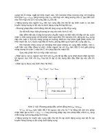
The scanning electron microscope (Fig. 1) can be subdivided into four systems. The illuminating/imaging system consist
of an electron source and a series of lenses that generate the electron beam and focus it onto the specimen. The
information system comprises the specimen and data signals released during irradiation as well as a series of detectors
that discriminate among and analyzes the data. The display system is simply a cathode ray tube (CRT) synchronized with
the electron detectors such that the image can be observes and recorded on film. Lastly, the vacuum system removes gases
that would otherwise interfere with operation of the scanning electron microscope column. These four systems are
described below in more detail. Supplementary information on the principles and instrumentation associated with SEM
can be found in the article "Scanning Electron Microscopy" in Volume 10 of ASM Handbook, formerly 9th Edition
Metals Handbook.
Fig. 1 Schematic cross section of a commercially available scanning electron microscope. Courtesy of JEOL
Illuminating/Imaging System
This system contains an electron gun that generates electrons as well as a series of convergent magnetic lenses that
reduces electron beam diameter and focuses the beam at the level of the specimen. The conventional electron gun consists
of a tungsten filament that generates electrons when heated to incandescence, an apertured shield centered over the tip of
the filament, and the anode, which is held at high positive potential relative to the filament. All three components act as
an electrostatic lens; heating the filament generates electrons that are accelerated by the potential difference between the
filament and anode into the imaging system. Alternate electron sources, such as the lanthanum hexaboride and field-
emission guns, are discussed in Ref 1.
In the imaging system, a series of magnetic lenses reduces the beam diameter from roughly 4000 to 10 mm at the
specimen level (Ref 2). Simultaneously, stray electrons are intercepted by apertures such that a collimated electron beam
strikes the specimen. Associated with the final lens is a scanning coil that deflects the electron beam in an x-y pattern; this
activity is reproduced on the observation screen as a raster pattern.
The illuminating/imaging system is responsible for several factors that ultimately define instrument performance,
including accelerating voltage, beam diameter, and levels of spherical aberration and astigmatism. Within instrumental
specifications for resolution, these factors are subject to operator control. As will be discussed below, the microscopist
rarely receives a perfect specimen for examination; consequently, to obtain the highest quality information from any
specimen, the scanning electron microscope must be maintained and operated at peak performance (Ref 3).
The accelerating voltage, variable from about 5 to 30 keV on most scanning electron microscopes, is the difference
in potential between the filament and anode. Accelerating voltage, V
o
, is related to atomic number, Z, and depth of
penetration of the incident beam into the specimen, d
p
, by:
2
0
a
p
WV
d
Z
ρ
∝
where W
a
is atomic weight and ρ is density. A secondary effect is the formation of an excitation volume considerably
larger than the beam diameter. Consequently, metal specimens are examined at high voltages (25 to 30 keV),
nonconductive but coated specimens at moderate voltages (~15 keV), and nonconductive, uncoated specimens at low
voltages (~5 keV). Figure 2 shows a Monte Carlo projection of electron trajectories in tungsten and aluminum (note the
differing sizes of the volumes). The excitation volume is an important quantity because it is the source of data signals
used for imaging and analysis. The location of the excitation volume depends on the angle of incidence of the electron
beam relative to the specimen surface. This geometry must be known for correct interpretation of x-ray data.
Fig. 2 Monte Carlo projections of the trajectory of incident electrons (top) and emitted x-
rays (bottom).
Projections are for tungsten (left) and aluminum (right). Note the effect of specimen tilt on the location of the
excitation volume.
Beam diameter, or spot size, is the width of the beam incident upon the specimen surface. As shown in Fig, 2, it is
considerably smaller than the excitation volume. A general rule is that smaller spot sizes always produce higher resolution
images. However, at very small spot sizes and beam currents, the signal-to-noise ratio may increase, causing a loss in
resolution. Smaller spot sizes are used for image recording; larger spot sizes may be required for x-ray analysis,
backscattered electron imaging, and TV mode operation.
Focus and magnification are also controlled by the magnetic lenses. Focus is achieved by varying the current passing
through the objective lens. Magnification is the ratio of the size of the display area on the CRT to the area of the specimen
scanned. Because a change in magnification involves simply scanning a larger or smaller area, the image should always
be focused at least two magnification steps higher than the desired level. This ensures that photographic enlargements will
exhibit the same clarity as the original micrograph.
Digital readouts of magnification are not very sensitive; a better indicator is the micron bar imprinted directly onto the
micrograph. Because the micron bar is sensitive to both focus and magnification settings, dimensions in enlargements can
be measured. However, serious errors arise if very accurate measurements are required, as in the analysis of fatigue crack
growth rates. Excessive parallax and other factors complicate the issue. Where high levels of sensitivity are required,
internal calibration with commercially available grating replicas is a good starting point, followed by quantitative analysis
of stereo pairs, as discussed in the section "Display System" in this article.
Astigmatism is an optical aberration caused by minute flaws in the magnetic-lens coilings. It is manifested as a
distortion in shape as focus is varied; for example, a circle forms an ellipse on either side of focus. This asymmetry is
compensated for by incorporating weak lenses called stigmators into the lens. The stigmators are of variable amplitude
and direction, which oppose and thus cancel the lens asymmetry. Astigmatism must be regularly corrected at a
magnification level (~20,000×) roughly double the typical operating magnification.
Spherical aberration arises because an electromagnetic field is strongest along the center of the optical axis and
becomes progressively weaker at its periphery. Electrons passing through these different zones are influenced at different
magnitudes. This aberration is relieved by intercepting peripheral electrons with apertures. In general, smaller apertures
(50-μm bore size) are used closest to the specimen level, and larger apertures (~200 μm) are used closest to the electron
gun. Image clarity and depth of field are both enhanced with small final apertures. As expected, the apertures must be
centered in the optical axis and must be regularly replaced because of the accumulation of contaminants.
Maintenance of the illumination/imaging system requires replacement of filaments (average service life, 40 h),
apertures, and the column liner tube as well as alignment of the column. Manufacturer operating manuals should be
consulted for maintenance procedures. Additional information can be found in Ref 4.
Information System
Electron Signals. Various data signals are simultaneously released by an irradiated specimen, and in the presence of
appropriate detectors, the signals can be analyzed (Fig. 3). Data signals arise from either elastic (electron-nucleus) or
inelastic (electron-electron) collisions. Elastic collisions produce backscattered electrons carrying topographic and
compositional data (Ref 5, 6). Inelastic collisions deposit energy within the specimen, which then returns to the ground
state by releasing secondary electrons, x-rays, and heat phonons.
The conventional SEM image consists of more secondary
electrons than backscattered electrons. An important
difference between these types of electrons is their relative
energy; backscattered electrons retain 80% of the incident
beam energy, whereas secondary electrons are of low energy
(~4 eV). Therefore, backscattered electrons follow a line-of-
sight trajectory and are detected only if they intersect the
electron detector. In comparison, secondary electrons are
attracted toward the detector by a positively charged Faraday
cage and can follow a curved trajectory. The conventional
Everhart-Thornley electron detector is ideal for analyzing
secondary electrons, but its geometry within the scanning
electron microscope is such that it detects only a fraction of
the backscattered electrons emitted by the specimen (Ref 7).
This secondary electron detector is positioned 90 ° relative to
the optical axis, and the specimen is tilted 10 to 30 ° to
enhance electron collection. In contrast, backscattered
electron detectors, such as the Robinson detector (Ref 8), are
located immediately beneath the final pole piece, and the
specimen is perpendicular to the optical axis (Fig. 3).
The advantage of distinguishing between secondary and
backscattered electrons is that the latter can be used for atomic number imaging; the number of backscattered electrons
reflected by a specimen increases with atomic weight. This is a powerful technique when used in conjunction with x-ray
analysis. As shown in Fig. 3, backscattered electrons originate from a zone closest to the x-ray excitation volume. In
failure analysis, atomic number contrast is used in the analysis of segregation, plating defects, and composite failures.
Effect of Specimen/Instrument Geometry. The geometry of the specimen, optical axis, and detector influences
data collection. The specimen is manipulated with x,y,z tilt, and rotational controls. The z-axis controls specimen height,
also known as working distance. A large working distance increases depth of field and decreases the lower limit of
magnification; the converse is true for small working distances. A compromise for imaging is to position the specimen
surface immediately at or slightly below the level of the secondary electron detector. For x-ray analysis, the specimen
should be at the level of the detector because x-rays follow a line-of-sight trajectory. Usually, only minor adjustments of
the z-axis are required to optimize detection of both signals.
Image clarity is also affected by specimen tilt. Secondary electron and x-ray collection can be maximized by tilting the
specimen toward the detector. The optimum angle depends on specimen topography; in general, larger angles are required
for smoother specimens. As shown in Fig. 2, the degree of tilt will affect the position of the excitation volume. This is
crucial for valid interpretation of point x-ray analysis because the data may originate from a position that does not
correspond exactly to the SEM image.
X-Ray Signals. Characteristic x-rays are distinct quanta of energy released from excited atoms. Specimen composition
is analyzed by measuring x-ray energy or wavelength. X-rays arise from electron transitions within the orbitals of an atom
(Fig. 4). Although there is some overlap among x-ray energies, all atoms generally possess at least one x-ray, or spectrum
of x-rays, that is unique to that element.
Fig. 3 Origin and detection of data signals
Energy-dispersive spectroscopy (EDS) is
the more common method of x-ray analysis used
in SEM. The conventional system can
quantitatively analyze elements with Z exceeding
or equal to 11 (sodium) (Ref 9). Windowless
detectors permit light element detection (Ref 10,
11). All x-rays ranging from about 0.7 to 13 keV
are simultaneously detected. Standard tables of x-
ray energy are available for manual data reduction,
but modern spectrometers automatically identify
each peak and its relative intensities (Ref 12).
Wavelength-dispersive spectroscopy
(WDS) uses a crystal spectrometer for the
detection of specific x-rays. Unlike EDS, a
specific wavelength is tuned in and analyzed. This
is a higher-resolution technique, but is more
frequently associated with electron probe x-ray
microanalysis than with SEM (Ref 13, 14, 15).
The advantage of conducting an x-ray analysis
with the scanning electron microscope is that the
area to be analyzed is visualized directly on the
CRT; that is, at low magnification, one may
analyze the bulk specimen, then increase
magnification and selectively analyze smaller
areas. However, the effects of geometry on
location of the excitation volume, as shown in Fig.
2 and 3, should be considered. To identify the
sources of x-ray emission, x-ray or dot maps are
produced by feeding the x-ray data for a given
element back into the scanning electron
microscope (Ref 16). Direct correlations between
structure and composition can be made by
recording the x-ray spectrum, dot map, and
electron image. Dot maps are very useful for sorting inclusions, demonstrating corrosion sites, and illustrating any type of
atomic number difference, especially in conjunction with backscattered electron imaging.
A great deal of information is available on x-ray analysis. Manufacturer's publications are good sources, as are Ref 4, 12,
14, and 17 and the articles "Scanning Electron Microscopy" and "Electron Probe X-Ray Microanalysis" in Volume 10 of
ASM Handbook, formerly 9th Edition Metals Handbook.
Thermal-wave imaging is a near-surface high-resolution technique that produces images resulting from localized
changes in thermal parameters (Ref 18). Although this technique is more widely used to analyze microelectronic devices,
it has application in metallurgy for the detection of subsurface (5 to 10 μm) defects and the imaging of metallographic
features of unpolished samples.
In Situ Studies. The advent of large scanning electron microscope specimen chambers has permitted design of devices
for the in situ analysis of mechanical behavior, such as fatigue crack initiation and propagation studies. Fatigue crack
initiation has been studied (Ref 19), and fatigue cracks near the threshold value have been analyzed (Ref 20). Other
devices include those for the analysis of wear (Ref 21, 22), high-temperature in situ oxidation (Ref 23, 24), fiber-
reinforced metal matrix composites (Ref 25), and in situ evaluation of ductile material behavior (Ref 26, 27). Videotaping
of such experiments provides a microscopic view of fracture mechanisms.
Display System
Scanning electron microscopy images are displayed on a CRT synchronized with the imaging system. Micrographs are
recorded from a high-resolution CRT, usually onto Polaroid film. Very slow scan rates (30 to 120 s) are used to improve
the signal-to-noise ratio. Contrast and brightness are modulated by the operator of the scanning electron microscope. A
Fig. 4 Origin of x-rays as shown in the Bohr model of the atom
good micrograph exhibits a range of gray levels; as the number of gray levels increases, so does the information content
of the micrograph. The operating parameters that influence the quality of the micrograph include correct accelerating
voltage, small beam spot size, optimum specimen geometry, and column alignment. The specimen itself must be clean
and conductive. Detailed information on SEM photography can be found in Ref 4, 28, 29, and 30.
Most scanning electron microscopes have various signal-processing devices that modulate the image. Gamma modulation
suppresses very dark or light levels, thus intensifying intermediate gray levels; it is used for specimens having very rough
surfaces. Other devices include split screens for display of dual magnification or different imaging modes, for example,
the side-by-side display of secondary electron and backscattered electron images of the same area.
The most crucial aspect of image recording for fractography is to maintain orientation and perspective. In general, only
selected areas of a fracture surface are examined in depth, for example, the fracture origin. If the specimen exhibits
multiple fracture modes, usually visible with a binocular microscope, the different areas are documented (Fig. 5).
Consequently, to maintain orientation, the microscopist should use a macrophotograph or detailed sketch to identify sites
where SEM photos are recorded. The fractographs should progress from low to high magnification, with identifiable
features present in the series (Fig. 6). Such a correlation of macroscopic and microscopic features provides an excellent
record of fracture morphology and is invaluable for interpretation. A similar approach is used if the images are videotape.
Fig. 5
Radial marks (arrows) in the fibrous zone of a bolt fractured under conditions of tensile overload. The
morphologies of the different texture zones are shown in the SEM fractographs: ductile fracture (left) and
transgranular fracture (right).
Fig. 6
(a) Chevrons (arrows) emanating from the fracture origin in a bolt that failed under conditions of
bending overload. (b) SEM fractographs of the origin and fracture surface shown in (a)
Stereo Imaging. A serious problem often encountered in SEM fractography is perspective distortion due to incorrect
perception of the direction of illumination. This artifact is eliminated by stereo imaging, which involves recording the
same field of view twice, each at slightly different orientations, then simultaneously viewing the stereo pair. The correct
relationships are restored, and valid spatial judgments replace subjective impressions.
The tilt method of stereo recording can be used with any scanning electron microscope as follows:
• Select and record the desired field of view, noting the tilt value of the specimen stage
• Mark the location of a prominent surface feature on the observation screen with a wax pencil
•
Tilt the specimen about 7 ° (stereo angle), and realign the prominent features beneath the wax pencil
mark
• Refocus the image using the z-axis control; do not refocus with the lens controls
• Adjust brightness and contrast, and record the image
Figure 7 illustrates the tilt method for stereo SEM. Stereo pairs are viewed using simple pocket viewers, double-prism
viewers, or a mirror stereoscope (Ref 31). Methods of stereo projection are discussed in Ref 32 and 33.
Fig. 7
Stereo pair showing deep dimples in the fracture surface of commercially pure titanium. Average grain
size is 46 μm. Large dimples originated at grain-
boundary triple points. Note small dimples at rim that
nucleated at dislocation cell walls. (M. Erickson-Natishan, University of Virginia)
Quantitative stereoscopy, which involves stereoscopic imaging and photogrammetric methods, is used for conducting
spatial measurements on stereo pairs (Ref 31, 34, 35, 36, 37). Detailed information on stereoscopic imaging and
photogrammetric methods can be found in the article "Quantitative Fractography" in this Volume.
In stereo photogrammetry, calibrated topographic maps of fracture surfaces can be generated by using a newly developed
adaptation of a Hilger-Watts stereoscope interfaced to a microcomputer. Transducer are mounted so as to follow the
motion of the viewing table and the motion of the micrometer used to superimpose the image of the light spot onto the
three-dimensional image of the surface below. The light spot (generated by two light sources mounted on either side of
the stereoscope and seen through half-silvered mirrors) is raised and lowered in order to appear to lie along the surface
below. The micrographs are translated, and the apparent height of the light spot is recorded with each trigger event,
generating a matrix of x-, y-, and z-coordinates when processed.
The voltage signals of the transducers are processed through an analog-digital conversion board and recorded on the
microcomputer. The arrays are then calibrated and normalized using user-supplied information on magnification and
parallax angle. THe array of calibrated x-, y-, and z-files can then be used to generate graphical output in various forms:
carpet plots, hidden line plots, or contour plots, depending on the need. Figure 8 shows a stereo pair of the fracture surface
of a Ti-10V-2Fe-3Al alloy and the corresponding carpet plot and contour plot.
Fig. 8 Stereo pair (top left and right) of a fractured Ti-10V-2Fe-
3Al alloy that was heat treated at 780 °C (1435
°F) for 3 h, water q
uenched, and aged for 1 h at 500 °C (930 °F). The corresponding carpet plot (bottom left)
and contour plot (bottom right) of the fracture surface are also shown. (J.D. Bryant, University of Virginia)
Vacuum System
The scanning electron microscope optical column and specimen chamber are operated under high-vacuum conditions (≤
10
-4
torr), to improve the quality of imaging, minimize contamination, and, in general, extend the service lives of all
components. A typical scanning electron microscope is equipped with a high-vacuum diffusion pump backed by a rotary
pump. Some manufacturers market turbo-molecular pumps, which relieve the contamination problems sometimes
associated with conventional systems. Because vacuum technology is standard regardless of the equipment it is associated
with, the scanning electron microscope vacuum system will not be discussed further in this article. Additional information
on vacuum pumping systems can be found in the article "Scanning Electron Microscopy" in Volume 10 of ASM
Handbook, formerly the 9th Edition Metals Handbook.
References cited in this section
1. A.N. Broers, IITRI/SEM Proceedings, 1975, p 661
2. B. Siegel, IITRI/SEM Proceedings, 1975, p 647
3. G.F. Pfefferkorn et al., SEM, Inc., Vol 1, 1978, p 1
4. B.L. Gabriel, SEM: A User's Manual for Materials Science, American Society for Metals, 1985
5. D.E. Newbury, IITRI/SEM Proceedings, Vol 1, 1977, p 553
6. V.N. Robinson and E.P. George, SEM, Inc., Vol 1, 1978, p 859
7. T.E. Everhart and R.E.M. Thornley, J. Sci Inst., Vol 37, 1960, p 246
8. V.N.E Robinson, J. Phys. E. Sci, Instrum., Vol 7, 1974, p 650
9. R. Woldseth, X-ray Energy Spectrometry, Kevex Corporation, 1973
10.
R.G. Musket, in Energy Dispersive X-ray Spectrometry,
NBS 604, National Bureau of Standards, 1981, p
97
11.
J.C. Russ and A.O. Sandborg in Energy Dispersive X-ray Spectrometry, NBS 604, National Bureau
of
Standards, 1981, p 71
12.
N.C. Barbi, Electron Probe Microanalysis Using Energy Dispersive X-ray Spectroscopy, PGT, Inc., 1981
13.
S.J.B. Reed, Electron Microprobe Analysis, Cambridge University Press, 1975
14.
J.I. Goldstein et al., Scanning Electron Microscopy and X-ray Microanalysis, Plenum Press, 1981
15.
D.T. Quinto et al., Low-Z Element Analysis in Hard Materials, Plenum Press, 1983
16.
J.J. McCarthy et al., in Proceedings of the Microbeam Analysis Society, 1981, p 30
17.
D.E. Newbury, SEM, Inc., Vol 2, 1979 p 1
18.
A. Rosenscwaig, Science, Vol 218, 1982 p 223
19.
K. Wetzig et al., Pract. Metallogr., Vol 21, 1984, p 161
20.
M. Schaper and D. Boesel, Prakt. Metallogr., Vol 22 (No. 4), 1985, p 197
21.
G. Gille and K. Wetzig, Thin Solid Films, Vol 110 (No. 1), 1983, p 37
22.
S.V. Prasad and T.H. Kosel, in Wear of Materials, American Society of Mechanical Engineers, 1983, p 121
23.
E. Kny et al., J. Vac. Sci. Technol., Vol 17 (No. 5), 1980, p 1208
24.
S.K. Verma et al., Oxid. Met., Vol 15 (No. 5-6), 1981, p 471
25.
D.L. Davidson et al., in Mechanical Behavior of Metal/Matrix Composites,
American Institute of Mining,
Metallurgy, and Petroleum Engineers, 1982, p 117
26.
Z.Q. Hu et al., in In Situ Composites IV, Elsevier, 1981
27.
F. Mousy, in Advances in Fracture Research, Vol 5, Pergamon Press, 1982, p 2537
28.
H. Horenstein, Black and White Photography: A Basic Manual, Little, Brown and Co., 1974
29.
H. Horenstein, Beyond Basic Photography, Little, Brown and Co., 1977
30.
C.B. Neblette et al., Photography: Its Materials and Processes, Van Nostrand Reinhold, 1976
31.
A. Boyde, SEM, Inc., Vol 2, 1979, p 67
32.
V.C. Barber and C.J. Emerson, Scanning, Vol 3, 1980, p 202
33.
W.P. Wergin and J.B. Pawley, SEM, Inc., Vol 1, 1980, p 239
34.
P.G.T. Howell and A. Boyde, IITRI/SEM Proceedings, 1972, p 233
35.
A. Boyde, IITRI/SEM Proceedings, 1974, p 101
36.
A. Boyde, SEM, Inc., Vol 1, 1981, p 91
37.
P.G.T. Howell, Scanning, Vol 4, 1981, p 40
Scanning Electron Microscopy
Barbara L. Gabriel, Packer Engineering Associates, Inc.
Specimen Preparation
The microscopist must know the objectives of an SEM examination before preparing a specimen. Different preparation
protocols are used, depending on whether SEM is required alone or in combination with x-ray analysis, particularly when
the specimen is too large for the specimen chamber or is nonconductive. In some litigation cases, use of an inappropriate
preparation method can be disastrous. The least aggressive method of preparation should be selected for any fracture
specimen.
The major criteria for SEM specimen preparation are that the specimen be conductive, clean, and small enough to enter
the specimen chamber. If the specimen is too large, replicas composed of cellulose acetate or dental-impression media are
prepared and coated with a conductive thin film (Ref 4, 38). Cellulose acetate replicas are also used to remove and
simultaneously preserve oxidation products that obscure the specimen surface. The fracture surface morphology can be
analyzed by direct examination of the fracture, and the products held within the replica can be identified by coating the
replica with thin carbon film. The handling and cleaning of fracture surfaces are the most important aspects of fracture
specimen preparation. Methods for handling, sectioning, and cleaning fractographic specimens are described in the article
"Preparation and Preservation of Fracture Specimens" in this Volume.
In most cases, a metal fracture can be directly examined in the scanning electron microscope. After cleaning, the
specimen is mounted in a specimen holder or on substrate using conductive paint or tape (Ref 39). Substrates include
aluminum stubs and carbon planchets; the latter is preferred for x-ray analysis. The paint or tape must be positioned such
that the area of interest is not obscured. With large specimens, it is helpful to identify the area of interest with small
arrows cut from metallic tape; their position and orientation can be indicated on both the macrophotograph and low-
magnification micrographs to facilitate correlations. At higher magnifications, these overviews can be used as maps to
pinpoint location and orientation.
Replicas and other nonconductive specimens are coated with a conductive thin film for SEM examination. Nonconductive
specimens accumulate a net negative charge that interferes with imaging unless examined at very low accelerating
voltages (~5 keV). Coating the specimen permits use of higher voltages (15 to 20 keV), which significantly enhances
image quality. Metallic coatings (gold or chromium) are preferred for imaging purposes because they increase the image-
forming electron yield; such coatings are prepared by thermal evaporation or sputter coating. Carbon coatings prepared by
evaporation are used for x-ray analysis because the surface film is nearly transparent to x-rays.
Thermal Evaporation. Evaporated thin films are prepared in a bell jar under high-vacuum conditions by resistance
heating of a metal wire or basket, which holds the evaporant above the specimen to be coated. At the vaporization
temperature of the metal, atoms are released and follow a line-of-sight trajectory until they strike the specimen surface.
As more metal vaporizes, a thin film will gradually adhere and eventually coat the specimen. If the specimen if held
stationary and at an angle relative to the source, the deposition is oblique. This is the technique of shadowing, which is
used to highlight surface features. In fractography, shadowing is used to enhance the fidelity of very fine fatigue striations
and the contrast of faint river patterns in cleavage fracture; the shadow is deposited in the direction of crack propagation.
If the specimen is mounted on a planetary stage in motion during evaporation, a continuous thin film is deposited. The
latter is preferred for coating nonconductive specimens, because film continuity is required for conductivity.
Assuming that all other factors are constant, the metal used for evaporation determines the structure of the coating. In
general, the higher the vaporization temperature of the metal, the finer the thin film. Gold with a vaporization temperature
of 1465 °C (2670 °F) produces a coarse-grain film, while platinum (2090 °C, or 3795 °F) produces a finer film. Alloys
such as platinum-carbon form very fine-grain films. The latter are required for transmission electron microscopy (TEM),
but coarser films are adequate for routine SEM fractography because the grain rarely becomes objectionable and
interferes with image quality. Finer films are required only when resolution exceeds approximately 8 nm and
magnification is greater than 40,000×
Carbon thin films are used for x-ray analysis or as a preliminary coating to enhance adhesion of metal films. The vacuum
bell jar is used, but is modified such that two carbon electrodes are used in place of a tungsten substrate for a metal wire.
The carbon is evaporated by passing an alternating current of 20 A at 30 V through the electrodes. More detailed
descriptions of this techniques and of thermal evaporation are available in Ref 4 and 40. Shadowing is also discussed in
the article "Transmission Electron Microscopy" in this Volume.
Sputter coating involves the erosion of metal atoms from a target by an energetic plasma under low-vacuum
conditions. This technique is preferred over evaporation for coating rough-surface specimens, because metal atoms
released from the target are deflected by gas molecules within the chamber and thus approach the specimen from all
directions. For example, replicas of ductile fracture surfaces often have an exaggerated topography, and it is difficult to
coat the cavities of dimples without increasing film thickness when thermal evaporation is used. With sputter coating, the
cavities will be coated without increasing thickness.
The diode sputter coater consists of the specimen stage (anode) and a small bell jar containing a metal target (usually
gold) that functions as a cathode. Under low-vacuum conditions (~10
-2
torr, or 1.3 Pa), argon or nitrogen is bled into the
chamber and forms a plasma during glow discharge. These energetic ions strike the metal target, and a transfer of
momentum causes metal atoms to be ejected from the target. The metal atoms are attracted toward the specimen stage by
the potential difference between the target and stage. Because heat is generated during sputtering, some diode coaters are
equipped with cooled specimen stages (Ref 41) or are modified into triode units (Ref 42). Sputter coating is also
discussed in Ref 4, 43, 44, and 45.
References cited in this section
4. B.L. Gabriel, SEM: A User's Manual for Materials Science, American Society for Metals, 1985
38.
C.H. Pameijer, SEM, Inc., Vol 2, 1978 p 831
39.
J.A. Murphy, SEM, Inc., Vol 2, 1982, p 657
40.
C.C. Shiflett, in Thin Film Technology, R.W. Berry et al., Ed., Van Nostrand Reinhold, 1968, p 113
41.
P.N. Panayi et al., IITRI/SEM Proceedings, Vol 1, 1977, p 463
42.
P. Ingram et al., IITRI/SEM, Proceedings, Vol 1, 1976, p 75
43.
P. Echlin, IITRI/SEM Proceedings, 1975, p 217
44.
P. Echlin, SEM, Inc., Vol 1, 1978, p 109
45.
P. Echlin, SEM, Inc., Vol 1, 1978, p 79
Scanning Electron Microscopy
Barbara L. Gabriel, Packer Engineering Associates, Inc.
SEM Fractography
The general features of ductile and brittle fracture modes are summarized in this section. More detailed information on
fracture modes and the effect on fracture morphologies of environmental factors, such as corrosion, temperature, stress
state, and strain rate, can be found in the article "Modes of Fracture" in this Volume. Overviews on fractography (Ref 46,
47, 48, 49, 50, 51) and various fractographic atlases (Ref 52, 53, 54, 55) should also be consulted.
Ductile and brittle are terms that describe the amount of macroscopic plastic deformation that precedes fracture. Ductile
fractures are characterized by tearing of metal accompanied by appreciable gross plastic deformation and expenditure of
considerable energy. Ductile tensile fractures in most materials have a gray, fibrous appearance and are classified on a
macroscopic scale as either flat (perpendicular to the maximum tensile stress) or shear (at a 45 ° slant to the maximum
tensile stress) fractures.
Brittle fractures are characterized by rapid crack propagation with less expenditure of energy than with ductile fractures
and without appreciable gross plastic deformation. Brittle tensile fractures have a bright, granular appearance and exhibit
or no necking. They are generally of the flat type, that is, normal (perpendicular) to the direction of the maximum tensile
stress. A chevron pattern may be present on the fracture surface, pointing toward the origin of the crack, especially in
brittle fractures in flat platelike components. Fractographic features that can be observed without magnification or at low
magnifications are discussed in the article "Visual Examination and Light Microscopy" in this Volume.
These terms can also be applied, and are applied fracture on microscopic level. Ductile fractures are those that occur by
microvoid formation and coalescence, whereas brittle fractures can occur by either transgranular (cleavage,
quasicleavage, or fatigue) or intergranular cracking. Intergranular fractures are specific to certain conditions that induce
embrittlement. These include embrittlement by thermal treatment or elevated-temperature service and embrittlement by
the synergistic effect of stress and environmental conditions. Both types are discussed below. Additional information can
also be found in the article "Ductile and Brittle Fractures" in Volume 11 of ASM Handbook, formerly 9th Edition of
Metals Handbook.
Ductile Fracture. Examination of ductile fracture surfaces by SEM reveals information about the type of loading
experienced during fracture, the direction of crack propagation, and the relative ductility of the material (Ref 56, 57, 58).
The shape of the dimples produced is determined by the type of loading the component experienced during fracture, and
the orientation of the dimples reveals the direction of crack extension.
Equiaxed or hemispheroidal dimples are cupshaped, and they form under conditions of uniform plastic strain in the
direction of applied tensile stress; equiaxed dimples are typically produced under conditions of tensile overload (Fig. 9).
In comparison, elongated dimples shaped like parabolas result from nonuniform plastic-strain conditions, such as bending
or shear overloads (Fig. 10). These dimples are elongated in the direction of crack extension and reveal the origin of the
fracture. Orientation is critical in this fracture mode; the microscopist should observe the conditions described earlier
regarding mapping macro- and micro-fractographs. Similar conditions should be observed when examining fractures due
to torsional shear and bending overloads.
Fig. 9 Formation of dimples under conditions of tension using a copper test specimen.
Note that the dimples
are equiaxed. 750×