Volume 05 - Surface Engineering Part 5 ppt
Bạn đang xem bản rút gọn của tài liệu. Xem và tải ngay bản đầy đủ của tài liệu tại đây (1.76 MB, 160 trang )
Boric acid, g/L (oz/gal) 50 (7)
Temperature, °C (°F) 60 (140)
pH 3-4
Anodes
(a)
Platinized niobium (insoluble)
Organic additives None
Pure gold
Potassium citrate, g/L (oz/gal) 150 (20)
Citric acid, g/L (oz/gal) 15 (2)
Potassium phosphate, g/L (oz/gal)
26 (3)
Boric acid, g/L (oz/gal) 72 (10)
Gold metal, g/L (oz/gal) 8.2 (1)
Temperature, °C (°F) 60 (140)
pH 3.5-4.0
Anodes Platinized titanium
Hard gold
Citric acid, g/L (oz/gal) 65 (9)
Potassium citrate, g/L (oz/gal) 50 (7)
Cobalt, g/L (oz/gal)
(b)
0.5-0.6(0.07-0.08)
Gold, g/L (oz/gal) 8.2 (1)
pH 3.8-4.0
Temperature, °C (°F) 32-38 (90-100)
(a)
When using soluble nickel anodes with reversing pulse modes, the use of an anode activator such as chloride is not required because the
reversing current keeps the anode active and soluble.
(b)
The higher voltage of pulse plating relative to continuous dc plating favors the deposition of the alloying agent. The operator should analyze
the deposits to determine if the amount of cobalt in the solution should be adjusted. In most cases, the amount of available cobalt (or other
alloying agent) should be reduced (from the amount used with continuous current) to obtain the desired properties.
Additives. The polarization imposed by the power pattern on the bath reduces, or even eliminates, the need for some
addition agents. In many cases, additives can actually inhibit the effectiveness of the pulsed-current pattern. For example,
large-molecule additives do not respond as they do under conventional power; in a high-frequency pulse field, their
molecular size is a disadvantage. Small-molecule organics or inorganics will generally function well as additives. In many
cases, the use of brighteners can be reduced as much as 90% without diminishing the brightness of the deposit because of
the improved grain structures. If brightener levels are not reduced, longer pulses i.e., lower frequencies and/or higher
duty cycles may be required (Ref 3).
Electrolyte conductivity must be maintained at a high level to allow the peak pulse current to be completely effective.
If the conductivity is not high enough, an excess in voltage will be required to attain the desired peak current. Such peaks
are power-inefficient and less effective.
Anode-to-cathode ratios for pulse plating are rarely the same as those for conventional power applications.
Generally speaking, in acid or alkaline nonchelating formulations, the anode area should be reduced. In cyanide or other
chelating formulations, the reverse is generally the case, and a greater anode area is required.
Temperature and agitation conditions for conventional processes may also have to be altered for modulated
power pattern plating. Unfortunately, no general rule applies; each application has its own requirements, and optimum
conditions must be established on a case-by-case basis.
Reference cited in this section
3.
J. Padden, J. Lochet, and C. VanHorn, "Improvement of E
lectrodeposition through Modulated dc Power
Patterns," 1981
Equipment Modification
One factor that should always be checked when planning a change from conventional to pulsed-current power is the tank
electrical contact system. Some anode and/or cathode contacts that may be perfectly suitable for conventional plating may
present unwanted resistance to high-frequency peak currents. Overlooking this factor may prevent the realization of the
full benefits of a modulated power supply.
The major consideration, of course, is the power system itself. Existing rectifiers may or may not be suitable for use with
modulated periodic reverse or direct pulse units. For pulse plating, a high-voltage, quick-response rectifier is required,
and the lower the ripple, the more precise and predictable the output. Although pulse units are available for use with
existing power supplies, models with self-contained rectifiers give greater assurance that full benefit of the control system
will be realized.
Pulse units with self-contained power can be operated in either a constant-average-current or constant-voltage mode. The
significance of this option is illustrated in Fig. 8. Figure 8(a) depicts a pulse train with a 50% duty cycle. The average
current delivered is 50% of the peak value. Figure 8(b) shows the effect of reducing the duty cycle to 25% when in a
constant-voltage mode. The peak current remains the same, but the average current changes directly with the duty cycle,
in this case dropping to half its former value. The current density of the pulsed current remains the same, but twice as
much real time is required to deliver the same amp-minutes of current. Figure 8(c) shows the effect of reducing the duty
cycle from 50 to 25% when operating in constant-average-current mode. In this case, the peak current changes inversely
to the duty cycle, increasing in value to maintain the same average current delivered as before but in shorter pulses.
Fig. 8 Effect of changes in the duty cycle on constant-average-current and constant-voltage pulsed-
current
plating. (a) 50% duty cycle, with average current 50% of the peak valu
e. (b) Duty cycle reduced to 25% in
constant-voltage mode; average current drops with duty cycle. (c) Duty cycle reduced to 25% in constant-
current mode; the peak current changes inversely to the duty cycle.
Although a change in frequency also changes the pulse width, it does not effect either peak or average current, regardless
of output mode (Fig. 9). Unlike conventional plating rectifiers, which are rated by average current capacity (ignoring the
ripple), modulated periodic reverse pulse units are normally rated by their peak current capacity. Because both peak and
average current values are intrinsic to modulated power pattern plating, both output capacities must be considered.
Depending on the internal circuitry of the unit, the average current output capacity of some models can be as low as 25 or
30% of the peak capacity. With such a low value for average current, the rated peak current output would be attained even
at average current capacity only if a duty cycle as low as 25 or 30% was used. Attempting to push average current up
would drastically shorten the life of the unit. Experience has shown that effective duty cycles are usually not less than
50% (although they can be as low as 10% for pure precious metals), and most units are designed to deliver an average
current capacity of 50 to 60% of the peak current capacity rating. However, any desired duty cycle can be used or
specified, but the operator must keep in mind that the average current is the percentage (duty cycle) of the peak rating.
Fig. 9 Effect of change of frequency on current pattern in pulsed-
current plating. Only pulse width is altered;
peak current, average current, and duty cycle remain constant.
Electroforming
Glenn Malone, Electroformed Nickel, Inc.; Myron E. Browning, Matrix Technologies
Introduction
ELECTROFORMING is the process by which articles or shapes can be exactly reproduced by electrodeposition on a
mandrel or form that is later removed, leaving a precise duplicate of the original. In certain applications, the mandrel is
designed to remain as an integral part of the final electroformed object. Electroforms themselves may be used as parents
or masters, usually with special passivating treatments so the secondary electroform can be easily removed. The same or
similar electrodeposition additives as those used for electroplating are required for electroforming to control deposit
stress, grain size, and other resultant mechanical properties in order to produce high-quality electroforms.
Early Applications
Electroforming was developed by a Prof. Jacobi of the Academy of Sciences in St. Petersburg, Russia in 1838 while
working with an engraved copper printing plate. While Prof. Jacobi had much difficulty in trying to separate the
replicated layer, he did note that once it was released the copper piece gave a perfect match of the original.
Prof. Boettger of Germany used nickel plating in the 1840s to produce exacting replicates of art objects by the
electroforming process. Electroformed articles, including sculpture, bas-reliefs, and statues from nickel, iron, or copper
were produced prior to 1870. Of special interest were the huge electroformed street lamps found in downtown Paris, the
production of which might be considered an enormous world-record accomplishment for electrodeposition. Iron
electroforming had early applications in the duplication of printing plates for coinage and currency because of its facility
to produce the highest accuracy in copying engraved masters.
Modern Applications
Today, the electroforming industry sees a number of high-tech uses for nickel, copper, iron, and alloy deposits to
electrofabricate exceedingly important components such as the main combustion chamber for the Space Shuttle, heart
pump components, body joint implants (prosthetic devices), high-precision optical scanners and holographic masters (for
credit cards, etc.), and recording masters. Fabrication of duplicating plates such as electrotypes, video disc stampers, and
currency embossing plates is manufacturing technology of today that employs electroforming. High-precision parts such
as molds and dies, where tolerances of internal surfaces are critical, are pieces for which electroforming can be used
advantageously. Optical memory disc mold cavities, including those for compact discs (CD and video discs) rely on the
virtually perfect surface reproduction found with the electroforming process. The average optical disc requires
impressions having a mean diameter of about 0.2 μm, which is well within the range of the electroforming processes
practiced today. One of the most widely used applications today is nickel disc mold electroforming.
Examples of electroforming applications are almost limitless, but a few of the more exacting examples are:
• Delicate, thin-
wall components such as lightweight heat or cold shields for aerospace applications,
hypodermic needles, foil, fine-mesh screen, and seamless tubing
• Parts that would be difficult to make by any other means, such as electr
onic waveguides, regeneratively
cooled thrust chambers for rocket engines, musical instruments, Pitot tubes, surface roughness gages,
and complex metal bellows
• Electroform joining (cold welding) of dissimilar metals that are difficult, if not impossible,
to join by
thermal means
Electroforming provides unique production advantages for precision operation in the textile, medical, aerospace,
communication, electronics, photocopying, automotive, and computer industries, and a number of other industries and is
used in the manufacturing of items such as textile printing screens, molds and dies, mesh products, bellows, compact disc
stampers, radar wave guides, and optical components.
Electroforming Determinants
Once the conceptual design for a part or component is developed, it is necessary to determine the fabrication process that
best meets the functional requirements of the hardware with least cost impact. The following advantages of
electroforming might be weighed:
• Parts can be mass produced with identical
tolerances from one part to the next, provided that mandrels
can be made with adequate replication.
•
Fine detail reproduction is unmatched by any other method of mass fabrication. Examples are the
electroforming of microgroove masters and stampers for the
record and compact disc industries, surface
roughness standards, and masters and stampers for holographic image reproduction.
•
Mechanical properties of electroformed articles can be varied over a wide range by selecting a suitable
plating electrolyte and a
djusting operating conditions. In some instances properties can be created in
electroformed metals that are difficult, if not impossible, to duplicate in wrought counterparts.
• Some shapes, particularly those with complex internal surfaces or passages, can
not be made by any
other method without excessive machining costs and scrap losses. These shapes are often easily
electroformed. Examples of such hardware are regeneratively cooled thrust chambers and waveguides
with compound curves.
• Gearing up to high-vo
lume production is relatively easy in many electroforming applications. For
example, a number of first-
generation positive replicas can be made from which a large number of
second-generation negatives can be electroformed. Such technology lends itself to m
any molds,
stamping devices, and optical surfaces requiring volume production.
•
The size and thickness of parts electroformed is not limited. Larger size can be accommodated by
increasing the tank volume in which the electrolyte is contained. Thickness may
vary from micrometers,
as in foils, to one or more centimeters, as is common in rocket thrust chamber shells.
•
Without the use of thermal joining techniques, metal layers can be applied by electroforming to provide
sandwich composites having a variety of
functional properties. Waveguides having an inner silver
electroformed layer for high electrical conductivity and an outer electroformed structural layer of
copper, nickel, nickel-cobalt, or other electrodepositable alloys are examples.
There are also some disadvantages of electroforming that must be considered, such as:
•
Electroforming is generally an expensive manufacturing method and is chosen when other methods are
more expensive or impractical to produce the desired hardware.
• Thick electroforming is very time-
consuming. Some deposits require days, or even weeks, to produce
the desired thickness. However, unlike precision machining, which is also very time-
consuming,
electroforming is not labor-intensive once the deposition process is started.
• Design
limitations exist in that deep or narrow recesses and sharp angles cause problems. Sudden and
severe change in cross section or wall thickness must be avoided unless subsequent machining can be
permitted.
• Most electrodeposits have some degree of stress in the as-
deposited condition that may cause distortion
after the mandrel is separated. Stress relieving and special attention to electrolyte chemistries and
operating parameters can lessen this problem.
• Any degradation in the mandrel surface quality will be reproduced in the electroform made from it.
The Electroforming Process
Electroforming is very similar to conventional electroplating as far as facilities and electrolytes are concerned. However,
the controls are more stringent, because the process consumes much more time and the product must be mechanically
sound and have low internal stress for dimensional acceptance. With long deposition times, high current densities at edges
and surfaces closer to the anodes result in significant buildup, leading to nodules and uncontrolled growth. This results in
further current density variations that can seriously affect the mechanical properties of the deposit.
In electroforming nickel, cobalt, or iron there is significant hydrogen codeposition that, if not removed, causes
pits in the deposit surface. Pumping filtered electrolyte through sprays over the surfaces being electroformed will
minimize the problem and aid in maintaining a smooth deposit. Areas of high current density showing excessive and
rough buildup can be corrected by using nonconducting shields as baffles to improve the current distribution. Where
recessed areas exist, low current density will be experienced. Undesired trace metal impurities will codeposit in such
locales, leading to inferior mechanical properties and surface appearance. Auxiliary or bipolar anodes may be necessary
to overcome the low-current problem.
Electroforming solutions may be used with one or more additives to control stress, brightness, leveling (smoothness), and
microstructure. When mechanical properties (including high ductility) or good electrical or thermal conductivity are
important in the deposit, it is advisable to use nonadditive electrolytes. Because most additives are organic compounds,
they are subject to decomposition if the deposit is subjected to elevated temperatures.
Stress-reducing agents are often used in nickel, iron, and cobalt plating baths to produce neutral or compressive residual
stresses. Such agents are usually grain-refining compounds also. These deposits are generally harder, have higher yield
strength, and exhibit less ductility than conventional deposits of the same metal. Advantages in neutral or compressively
stressed deposits are ease of removal of electroforms from mandrels and inhibition of growth of cracks in deposits should
they occur from impact. A problem with stress reducers in nickel is that sulfur codeposits form when the agent reacts at
the cathode, because most stress reducers contain sulfur. Brazing or welding such deposits causes sulfur to react with
nickel to form a nickel sulfide liquidus in the range of 483 °C (901 °F) to about 650 °C (1200 °F). This leads to the effect
known as "hot shortness" experienced in wrought nickels. Such deposits can be alloyed with as little as 1500 ppm Mg to
counter the problem.
Copper Electroforming. Acid sulfate electrolytes are the industry standard for copper electroforming. Additives are
usually employed for grain refining, leveling, and brightening. The mechanical property improvements achieved are
mostly a result of grain refining. Organic compounds capable of reducing copper oxides at the cathode may also be used
to produce an oxygen-free, high-conductivity copper equivalent (<10 ppm oxygen). Decomposition products from copper
bath additives will codeposit to degrade ductility. Without additives, acid sulfate baths produce copper with grain size
increasing proportionally to deposit thickness. Intergranular voids are created that seriously degrade mechanical
properties. A plating technique known as periodic current reversal will promote deposition of a copper deposit having
uniform grain size and excellent mechanical properties for thicknesses of 0.5 cm (0.2 in.) or greater. This procedure
requires plating in a conventional direction for a given period of time, followed by a reversal of current direction for a
lesser period of time. Although the process results in a slow rate of deposition, the benefits of good mechanical properties,
relatively smooth deposit surfaces, and ability to plate dense, thick deposits make this technique most useful.
Mandrel Types and Selection
Mandrels are either permanent or expendable. Permanent mandrels are usually metallic, but they can also be made of a
conductive plastic. They can be used repeatedly until surface wear or scratching renders them useless. The most widely
used permanent mandrels are made of metals that are resistant to adherent bonding by the metal being electroformed. The
300-series stainless steels are the preferred materials for permanent mandrels because of the naturally passive surfaces.
Substrates such as copper, brass, or steel may also be used, but these must be plated with chromium to provide a passive
surface for ease of separation. It is also possible to use copper or brass for engravure mandrels if they are chemically
passivated to prevent electroform bonding. Nickel is frequently employed for producing multiple first-generation replicas
for mass production of second-generation electroforms. Adherence on nickel is unpredictable, so it is advisable to
passivate the surfaces chemically.
Plastics are suitable for permanent mandrels where flat electroforms are involved and separation is relatively simple. Such
mandrels are made conductive by the silver reduction method (Ref 1) or by use of silver-filled paint. Plastic mandrels are
often used for the electroforming of Fresnel lenses. Glass plates can also be used as permanent mandrels containing
holographic imagery.
Expendable mandrels may consist of cast fusible metals, plaster, plastics, waxes, soluble metals, or wood. Fusible metals
are commonly alloys of tin, lead, bismuth, antimony, and cadmium. Aluminum is a popular expendable mandrel material
because it is easily machined and polished to close surface and dimensional tolerances. It is also easy to dissolve in
caustic solutions.
Reference cited in this section
1.
H. Narcus, Metallizing of Plastics, Reinhold Publishing Company, 1960
Mandrel Design and Preparation
Mandrels may be made to reproduce accurately external or internal surfaces. The reproduced surface will be precisely the
same as the surface upon which plating is initiated. The final plated surface will be rougher as the plated thickness
increases. Design features of importance are avoidance of deep grooves or recesses, avoidance of sharp internal angles,
and maintenance of liberal radii on corners. Figure 1 illustrates mandrel design considerations that should be followed.
Fig. 1 Factors to consider in electroforming mandrel design. Source: Ref 2
Permanent mandrels for electroforming concentric shapes must be designed with a draft or taper to permit removal of the
mandrel without damaging the electrodeposit or the mandrel. If this is not possible, expendable mandrels must be
considered. ASTM B 450 provides more guidelines in the design of electroformed articles (Ref 3). Preparation of
mandrels for electroforming is detailed in ASTM B 431 (Ref 4). Special design considerations are often given to
permanent mandrels being developed for complex parts that are to be produced in mass quantities or are of a complex
nature, requiring speedy release from the mandrel. In these cases, knockout blocks or key release sections are designed
into the mold, mandrel, or matrix to ensure quick and positive release and multiple uses of the master form.
References cited in this section
2.
A. Squitero, Designing Electroformed Parts, Machine Design, 9 May 1963
3.
ASTM B 450, "Standard Practice for Engineering Design of Electroformed Articles," ASTM
4.
ASTM B 431, "Standard Practice for Processing of Mandrels for Electroforming," ASTM
Electroforming Solutions and Operating Variables
Nickel Electroforming Solutions. Nickel, the most commonly electroformed metal, is plated from Watts, fluoborate,
and sulfamate solutions. The last is the most widely used due to lower stresses in the deposits and ease of operation.
Nickel is deposited from most baths with moderate to high tensile stress. If uncontrolled, this stress can make removal of
the mandrel difficult, can result in distorted parts after mandrel separation, and can even result in deposit cracking. In
general, the chloride-free sulfamate bath produces the lowest internal stresses of all the nickel baths. Typical nickel
sulfamate electrolyte compositions, operating conditions, and deposit mechanical properties are shown in Table 1. Effects
of changes in operating variables on mechanical properties of nickel sulfamate deposits are described in Table 2. Similar
information for all commonly used nickel electroforming baths is given in ASTM B 503 (Ref 5).
Table 1 Nickel electroforming solutions and selected properties of the deposits
Parameter Watts nickel Nickel sulfamate
NiSO
4
·6H
2
O 225-300 (30-40)
Ni(SO
3
NH
2
)
2
315-450 (42-60)
NiCl
2
·6H
2
O 37.5-52.5 (5-7) H
3
BO
3
30-45 (4-6)
Electrolyte composition, g/L (oz/gal)
H
3
BO
3
30-45 (4-6) NiCl
2
·6H
2
O 0-22.5 (0-3)
Operating conditions
Temperature, °C (°F) 44-66 (115-150) 32-60 (90-140)
Agitation Air or mechanical Air or mechanical
Cathode current density, A/dm
2
(A/ft
2
)
270-1075 (25-100) 50-3225 (5-300)
Anodes Soluble nickel Soluble nickel
pH 3.0-4.2 3.5-4.5
Mechanical properties
Tensile strength, MPa (ksi) 345-482 (50-70) 410-620 (60-90)
Elongation, % 15-25 10-25
Hardness, HV
100
130-200 170-230
Internal tensile stress, MPa (ksi) 125-186 (18-27) 0-55 (0-8)
Table 2 Variables affecting mechanical properties of deposits from nickel sulfamate electrolytes
Property Operational effects Solution composition effects
Tensile
strength
Decreases with increasing temperature to 49 °C, then increases
slowly with further temperature increase. Increases with increasing
pH. Decreases with increasing current density.
Decreases slightly with increasing nickel content.
Elongation Decreases as the temperature varies in either direction from 43 °C.
Decreases with increasing pH. Increases moderately with increasing
current density.
Increases slightly with increasing nickel content.
Increases slightly with increasing chloride content.
Hardness Increases with increasing temperature within operating range
suggested. Increases with increasing solution pH.Reaches a
minimum at about 13 A/dm
2
.
Decreases slightly with increasing concentration of
nickel ion. Decreases slightly with increasing
chloride content.
Internal
stress
Decreases with increasing solution temperature. Reaches a
minimum at pH 4.0-4.2. Increases with increasing current density.
Relatively independent of variation in nickel ion
content within range. Increases significantly with
increasing chloride content.
Copper electroforming solutions of significance are the acid sulfate and fluoborate baths. Table 3 lists typical
compositions, operating conditions, and mechanical properties for these baths. Changes in operating variables will affect
mechanical properties of copper sulfate deposits, as noted in Table 4. Similar information for effects of variable changes
on copper fluoborate deposits are found in ASTM B 503 (Ref 5).
Table 3 Copper electroforming solutions and selected properties of deposits
Parameter Copper sulfate Copper fluoborate
CuSO
4
·5H
2
O 210-240 (28-32) Cu(BF
4
)
2
225-450 (30-60) Electrolyte composition, g/L (oz/gal)
H
2
SO
4
52-75 (7-10) HBF
4
To maintain pH at 0.15-
1.5
Operating conditions
Temperature, °C (°F) 21-32 (70-90) 21-54 (70-129)
Agitation Air or mechanical Air or mechanical
Cathode current density, A/dm
2
(A/ft
2
)
1-10 (9.3-93) 8-44 (75-410)
Anodes Oxygen-free, high-conductivity copper or phosphorized
copper
Soluble copper
Mechanical properties
Tensile strength, MPa (ksi) 205-380 (30-55) 140-345 (20-50)
Elongation, % 15-25 5-25
Hardness, HV
100
45-70 40-80
Internal tensile stress, MPa (ksi) 0-10 (0-1.45) 0-105 (0-15)
Table 4 Variables affecting mechanical properties of deposits from acid copper sulfate electrolytes
Property Operational effects Solution composition effects
Tensile
strength
Decreases slightly with increasing solution
temperature. Increases significantly with
increase in cathode current density.
Relatively independent of changes in copper sulfate concentration
within the range suggested. Relatively independent of changes in
sulfuric acid concentration within the range suggested.
Elongation Decreases with increasing solution temperature.
Increases slightly with increasing cathode
current density.
High acid concentrations, particularly with low copper sulfate
concentration, tend to reduce elongation slightly.
Hardness Decreases slightly with increasing solution
temperature. Relatively independent of change
in cathode current density.
Relatively independent of copper sulfate concentration. Increases
slightly with increasing acid concentration.
Internal
stress
Increases with increasing solution temperature.
Increases with increasing cathode current
density.
Relatively independent of copper sulfate concentration. Decreases very
slightly with increasing acid concentration.
Iron Electroforming Solutions. Iron electroforming, while not in major industrial production today, is technically
usable if precautions are followed. Three types of electroforming baths exist as slightly acidic systems: sulfate, fluoborate,
and sulfamate systems. A fourth system is the highly acidic chloride system, which uses ferrous chloride/calcium chloride
operating between 88 and 99 °C (190 and 210 °F). Table 5 presents condensed details of the four baths and primary
operating conditions. Except for deposits from the chloride bath, all other baths produce iron deposits brittle in nature and
not usable without special thermal treatment, stress-reducing additives, or backup deposits to protect the brittle nature of
the iron films. The chloride deposits can be best used with a postplating heat treatment of 260 °C (500 °F) or above to
ensure ductility.
Table 5 Iron electroforming solutions and operating conditions
Parameter Value
Chloride bath
Ferrous chloride (dihydrate), g/L (oz/gal) 300-450 (40-60)
Calcium chloride, g/L (oz/gal) 150-185 (20-25)
Temperature, °C (°F) 90-99 (190-210)
pH (HCl) 0.2-1.8
Current density, A/dm
2
(A/ft
2
)
Without agitation
2-8.5 (20-80)
With agitation
2-21 (20-200)
Sulfate bath
Ferrous sulfate, g/L (oz/gal) 240 (32)
pH 2.8-3.5
Temperature, °C (°F) 32-65 (90-150)
Current density, max, A/dm
2
(A/ft
2
)
at 32 °C (90 °F)
4.3 (40)
at 65 °C (150 °F)
10 (100)
Surface tension, dynes/cm 40
Cathode agitation Desirable
Fluoborate bath
Iron fluoborate, g/L (oz/gal) 227 (30.3)
Metallic iron, g/L (oz/gal) 55.2 (7.37)
Sodium chloride, g/L (oz/gal) 10.0 (1.34)
Baumé, degrees, at 27 °C (80 °F) 19-21
pH (colorimetric) 3.0-3.4
Temperature, °C (°F) 57-63 (135-145)
Current density (cathode-average), A/dm
2
(A/ft
2
)
2-10 (20-90)
Tank voltage, avg 2-6
Sulfamate bath
Ferrous iron, g/L (oz/gal) 75 (10)
Ammonium sulfamate, g/L (oz/gal) 30-37 (4-5)
Sodium chloride, g/L (oz/gal) 37-45 (5-6)
Temperature, °C (°F) 50-60 (120-140)
Current density, A/dm
2
(A/ft
2
) 5.4 (50)
pH 2.7-3.0
Reference cited in this section
5.
ASTM B 503, "Standard Practice for Use of Copper and Nickel Electroplating So
lutions for Electroforming,"
ASTM
Process Controls
Because of the exacting products desired during electroforming, the controls are apt to be more stringent. Controlling
metal distribution, internal stress, nodular growth, and roughness are among the potential problems that are often found in
electroforming. Some of these problems are handled by using various addition agents, but special attention is often
required to monitor conditions during deposition. Other significant aspects of the electroforming process that demand
special consideration include the following.
Metal distribution relates to nonuniform deposition due to changes in mandrel configuration, throwing power of the
bath selected, placement in the plating tank, and other features of the deposits being produced. Attempting to retain the
best properties of the metal being deposited and at the same time maintain excellent throwing power is most difficult. One
can improve metal distribution by using proper racking designs, employing "thieves," "robbers," shields, or auxiliary or
conforming anodes, and completely mapping out the electrical requirements of the mandrel. Computer software programs
exist that aid in the design of cathode distribution systems.
Internal deposit stress is most important to control during, before, and after deposition. Before deposition it may
develop within the mandrel, resulting in unwarranted partial liftoff of the electroform before it is complete. During
deposition, symptoms of internal deposit stress are problems trying to separate the electroform from the mold, buckling or
blistering of the deposits, and cracking of the deposit during deposition or while it is separated from the master. Most of
these manifestations come from either the bath itself, impurities permitted in the bath (incomplete filtration), or lack of
control of the additives needed for the bath. Careful monitoring of all operating conditions is also important for deposit
stress control.
Roughness and "treeing" are conditions that may appear during electroforming if care is not taken. To minimize
roughness, the electroformer must watch the filtration rates, because even small dirt particles can be the nucleation sites
for rough deposits. Filtration rates may need to be as high as whole-solution-volume recycling once or more per hour.
Other aids in preventing roughness include using positive pressure of an inch or so with filtered air, plus keeping the
electroforming room in extra-clean condition.
The phenomenon of treeing occurs near the edges or corners of the mandrel or attachment areas. These can be minimized
by the use of shields, improved racking, or "thieving" to prevent excess current in unwanted areas. Leveling agents and
nodule suppressants may also be useful to reduce treeing. Often it becomes necessary to stop the electroforming, remove
the part, and machine off the excess deposit. One must remember to reactivate the electroform when replacing it in the
plating tank.
One other factor worthy of considering in minimizing roughness, pitting, burning, and sometimes treeing is to constantly
check solution agitation, whether by air, mechanical, cathode rod, or other means. Make sure that no grease, wear
particles, or other outside dirt enters the electroforming system by virtue of the agitation system.
Alloy Electroforming
Alloy electroforming using high-strength materials, such as nickel-cobalt, cobalt-tungsten, and even more complex alloys
involving tungsten and the iron group metals, has made some inroads for special applications. Microfabrication of
sensors, maskless jet systems, miniature computer components, and a host of newer devices rely on the properties of
many electrodeposited alloys and the precision of electroforming to produce such items. Bath chemistries, deposition
parameters (in some cases requiring pulse plating control), and fixturing are all very critical to control for optimal
production of these advanced products.
Future Applications
Such developments as composition-modulated alloys, nanophase composites, nonaqueous plating baths, and advanced
pulsed current controls are expected to open the field of electroforming to more complex and innovative applications.
Electroless Nickel Plating
Revised by Donald W. Baudrand, MacDermid Inc.
Introduction
ELECTROLESS NICKEL PLATING is used to deposit nickel without the use of an electric current. The coating is
deposited by an autocatalytic chemical reduction of nickel ions by hypophosphite, aminoborane, or borohydride
compounds. Two other methods have been used commercially for plating nickel without electric current, including (1)
immersion plating on steel from solutions of nickel chloride and boric acid at 70 °C (160 °F) and (2) decomposition of
nickel carbonyl vapor at 180 °C (360 °F). Immersion deposits, however, are poorly adherent and nonprotective, while the
decomposition of nickel carbonyl is expensive and hazardous. Accordingly, only electroless nickel plating has gained
wide acceptance.
Since gaining commercial use in the 1950s, electroless nickel plating has grown rapidly and now is an established
industrial process. Currently, hot acid hypophosphite-reduced baths are most frequently used to plate steel and other
metals, whereas warm alkaline hypophosphite baths are used for plating plastics and nonmetals. Borohydride-reduced
baths are also used to plate iron and copper alloys, especially in Europe.
Electroless nickel is an engineering coating, normally used because of excellent corrosion and wear resistance. Electroless
nickel coatings are also frequently applied on aluminum to provide a solderable surface and are used with molds and dies
to improve lubricity and part release. Because of these properties, electroless nickel coatings have found many
applications, including those in petroleum, chemicals, plastics, optics, printing, mining, aerospace, nuclear, automotive,
electronics, computers, textiles, paper, and food machinery (Ref 1). Some advantages and limitations of electroless nickel
coatings include:
Advantages
• Good resistance to corrosion and wear
• Excellent uniformity
• Solderability and brazeability
• Low labor costs
Limitations
• Higher chemical cost than electroplating
• Brittleness
• Poor welding characteristics due to contamination of nickel plate with nickel phosphorus deposits
•
Need to copper strike plate alloys containing significant amounts of lead, tin, cadmium, and zinc before
electroless nickel can be applied
• Slower plating rate, as compared to electrolytic methods
Reference
1.
K. Parker, "Recent Advances in Electroless Nickel Deposits, 8th Interfinish Conference," 1972 (Basel)
Bath Composition and Characteristics
Electroless nickel coatings are produced by the controlled chemical reduction of nickel ions onto a catalytic surface. The
deposit itself is catalytic to reduction, and the reaction continues as long as the surface remains in contact with the
electroless nickel solution. Because the deposit is applied without an electric current, its thickness is uniform on all areas
of an article in contact with fresh solution.
Electroless nickel solutions are blends of different chemicals, each performing an important function. Electroless nickel
solutions contain:
• A source of nickel, usually nickel sulfate
• A reducing agent to supply electrons for the reduction of nickel
• Energy (heat)
• Complexing agents (chelators) to control the free nickel available to the reaction
• Buffering agents to resist the pH changes caused by the hydrogen generated during deposition
• Accelerators (exultants) to help increase the speed of the reaction
• Inhibitors (stabilizers) to help control reduction
• Reaction byproducts
The characteristics of an electroless nickel bath and its deposit are determined by the composition of these components.
Reducing Agents
A number of different reducing agents have been used in preparing electroless nickel baths, including sodium
hypophosphite, aminoboranes, sodium borohydride, and hydrazine.
Sodium Hypophosphite Baths. The majority of electroless nickel used commercially is deposited from solutions
reduced with sodium hypophosphite. The principal advantages of these solutions over those reduced with boron
compounds or hydrazine include lower cost, greater ease of control, and better corrosion resistance of the deposit.
Several mechanisms have been proposed for the chemical reactions that occur in hypophosphite-reduced electroless
nickel plating solutions. The most widely accepted mechanism is illustrated by the following equations:
2
2223
()()2
abs
Catalyst
HPOHOHHPOH
Heat
−+−
+→++
(Eq 1)
Ni
2
+ 2H
abs
→
Ni + 2H
+
(Eq 2)
(H
2
PO
2
)
-
+ H
abs
→
H
2
O + OH
-
+ P
(Eq 3)
(H
2
PO
2
)
-
+ H
2
O
→
H
+
+ (HPO
3
)
2-
+ H
2
(Eq 4)
In the presence of a catalytic surface and sufficient energy, hypophosphite ions are oxidized to orthophosphite. A portion
of the hydrogen given off is absorbed onto the catalytic surface (Eq 1). Nickel at the surface of the catalyst is then reduced
by the absorbed active hydrogen (Eq 2). Simultaneously, some of the absorbed hydrogen reduces a small amount of the
hypophosphite at the catalytic surface to water, hydroxyl ion, and phosphorus (Eq 3). Most of the hypophosphite present
is catalytically oxidized to orthophosphite and gaseous hydrogen (Eq 4) independently of the deposition of nickel and
phosphorus, causing the low efficiency of electroless nickel solutions. Usually 5 kg (10 lb) of sodium hypophosphite is
required to reduce 1 kg (2 lb) of nickel, for an average efficiency of 37% (Ref 2, 3).
Early electroless nickel formulations were ammoniacal and operated at high pH. Later, acid solutions were found to have
several advantages over alkaline solutions. Among these are higher plating rate, better stability, greater ease of control,
and improved deposit corrosion resistance. Accordingly, most hypophosphite reduced electroless nickel solutions are
operated between 4 and 5.5 pH. Compositions for alkaline and acid plating solutions are listed in Table 1 (Ref 2, 3, 4, 5).
Table 1 Hypophosphite-reduced electroless nickel plating solutions
Alkaline Acid Constituent or
condition
Bath 1 Bath 2 Bath 3 Bath 4 Bath 5 Bath 6
Composition
Nickel chloride, g/L (oz/gal) 45 (6) 30 (4) 30 (4) . . . . . . . . .
Nickel sulfate, g/L (oz/gal) . . . . . . . . . 21 (2.8) 34 (4.5) 45 (6)
Sodium hypophosphite, g/L (oz/gal)
11 (1.5) 10 (1.3) 10 (1.3) 24 (3.2) 35 (4.7) 10 (1.3)
Ammonium chloride, g/L (oz/gal) 50 (6.7) 50 (6.7) . . . . . . . . . . . .
Sodium citrate, g/L (oz/gal) 100 (13.3)
. . . . . . . . . . . . . . .
Ammonium citrate, g/L (oz/gal) . . . 65 (8.6) . . . . . . . . . . . .
Ammonium hydroxide To pH To pH . . . . . . . . . . . .
Lactic acid, g/L (oz/gal) . . . . . . . . . 28 (3.7) . . . . . .
Malic acid, g/L (oz/gal) . . . . . . . . . . . . 35 (4.7) . . .
Amino-acetic acid, g/L (oz/gal) . . . . . . . . . . . . . . . 40 (5.3)
Sodium hydroxyacetate, g/L (oz/gal)
. . . . . . 10 (1.3) . . . . . . . . .
Propionic acid, g/L (oz/gal) . . . . . . . . . 2.2 (0.3) . . . . . .
Acetic acid, g/L (oz/gal) . . . . . . . . . . . . . . . 10 (1.3)
Succinic acid, g/L (oz/gal) . . . . . . . . . . . . 10 (1.3) . . .
Lead, ppm . . . . . . . . . 1 . . . . . .
Thiourea, ppm . . . . . . . . . . . . 1 . . .
Operating conditions
pH 8.5-10 8-10 4-6 4.3-4.6 4.5-5.5 4.5-5.5
Temperature, °C (°F) 90-95
(195-205)
90-95
(195-205)
88-95
(190-205)
88-95
(190-205)
88-95
(190-205)
88-95
(190-205)
Plating rate, μm/h (mil/h) 10 (0.4) 8 (0.3) 10 (0.4) 25 (1) 25 (1) 25 (1)
Aminoborane Baths. The use of aminoboranes in commercial electroless nickel plating solutions has been limited to
two compounds: N-dimethylamine borane (DMAB)-(CH
3
)
2
NHBH
3
, and H-diethylamine borane (DEAB) (C
2
H
5
)
2
NHBH
3
. DEAB is used primarily in European facilities, whereas DMAB is used principally in the United States. DMAB
is readily soluble in aqueous systems. DEAB must be mixed with a short chain aliphatic alcohol, such as ethanol, before it
can be dissolved in the plating solution.
Aminoborane-reduced electroless nickel solutions have been formulated over wide pH ranges, although they are usually
operated between 6 and 9 pH. Operating temperatures for these baths range from 50 to 80 °C (120 to 180 °F), but they
can be used at temperatures as low as 30 °C (90 °F). Accordingly, aminoborane baths are very useful for plating plastics
and nonmetals, which is their primary application. The rate of deposition varies with pH and temperature, but is usually 7
to 12 μm/h (0.3 to 0.5 mil/h). The boron content of the deposit from these baths varies between 0.4 and 5%. Compositions
and operating conditions for aminoborane baths are listed in Table 2 (Ref 2, 5, 6).
Table 2 Aminoborane- and borohydride-reduced electroless nickel plating solutions
Aminoborane Borohydride Constituent or
condition
Bath 7 Bath 8 Bath 9 Bath 10
Composition
Nickel chloride, g/L (oz/gal) 30 (4) 24-48 (3.2-6.4) . . . 20 (2.7)
Nickel sulfate, g/L (oz/gal) . . . . . . 50 (6.7) . . .
DMAB, g/L (oz/gal) . . . 3-4.8 (0.4-0.64)
3 (0.4) . . .
DEAB, g/L (oz/gal) 3 (0.4) . . . . . . . . .
Isopropanol, mL (fluid oz) 50 (1.7) . . . . . . . . .
Sodium citrate, g/L (oz/gal) 10 (1.3) . . . . . . . . .
Sodium succinate, g/L (oz/gal) 20 (2.7) . . . . . . . . .
Potassium acetate, g/L (oz/gal) . . . 18-37 (2.4-4.9) . . . . . .
Sodium pyrophosphate, g/L (oz/gal)
. . . . . . 100 (13.3)
. . .
Sodium borohydride, g/L (oz/gal) . . . . . . . . . 0.4 (0.05)
Sodium hydroxide, g/L (oz/gal) . . . . . . . . . 90 (12)
Ethylene diamine, 98%, g/L (oz/gal)
. . . . . . . . . 90 (12)
Thallium sulfate, g/L (oz/gal) . . . . . . . . . 0.4 (0.05)
Operating conditions
pH 5-7 5.5 10 14
Temperature, °C (°F) 65 (150) 70 (160) 25 (77) 95 (205)
Plating rate, μm/h (mil/h) 7-12 (0.5)
7-12 (0.5) . . . 15-20 (0.6-0.8)
Sodium Borohydride Baths. The borohydride ion is the most powerful reducing agent available for electroless nickel
plating. Any water-soluble borohydride may be used, although sodium borohydride is preferred.
In acid or neutral solutions, hydrolysis of borohydride ions is very rapid. In the presence of nickel ions, nickel boride may
form spontaneously. If the pH of the plating solution is maintained between 12 and 14, however, nickel boride formation
is suppressed, and the reaction product is principally elemental nickel. One mol of sodium borohydride can reduce
approximately one mol of nickel, so that the reduction of 1 kg (2 lb) of nickel requires 0.6 kg (1 lb) of sodium
borohydride. Deposits from borohydride-reduced electroless nickel solutions contain 3 to 8 wt% B.
To prevent precipitation of nickel hydroxide, complexing agents, such as ethylene diamine, that are effective between 12
to 14 pH must be used. Such strong complexing agents, however, decrease the rate of deposition. At an operating
temperature of 90 to 95 °C (195 to 205 °F), the plating rate of commercial baths is 25 to 30 μm/h (1 to 1.2 mil/h).
Compositions of a borohydride-reduced electroless nickel bath are also shown in Table 2 (Ref 6).
During the course of reduction, the solution pH decreases, requiring constant additions of an alkali hydroxide.
Spontaneous solution decomposition may occur if the bath pH is allowed to fall below 12. Because of the high operating
pH, borohydride plating baths cannot be used for aluminum substrates (Ref 2, 5, 7).
Hydrazine Baths. Hydrazine has also been used to produce electroless nickel deposits. These baths operate at 90 to 95
°C (195 to 205 °F) and 10 to 11 pH. Their plating rate is approximately 12 μm/h (0.5 mil/h). Because of the instability of
hydrazine at high temperatures, however, these baths tend to be very unstable and difficult to control.
Whereas the deposit from hydrazine-reduced solutions is 97 to 99% N, it does not have a metallic appearance. The
deposit is brittle and highly stressed with poor corrosion resistance. The stress and brittleness are likely due to
codeposition of small amounts of basic nickel salts, Ni(OH)
2
, and nitrogen. Unlike hypophosphite- and boron-reduced
nickels, hardness from a hydrazine-reduced electroless nickel has very little commercial use (Ref 2).
Energy
The amount of energy or heat present in an electroless nickel solution is one of the most important variables affecting
coating deposition. In a plating bath, temperature is a measure of its energy content.
Temperature has a strong effect on the deposition rate of acid hypophosphite-reduced solutions. The rate of deposition is
usually very low at temperatures below 65 °C (150 °F), but increases rapidly with increased temperature (Ref 5). This is
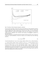
illustrated in Fig. 1, which gives the results of tests conducted using bath 3 in Table 1 (Ref 7). The effect of temperature
on deposition in boron-reduced solutions is similar. At temperatures above 100 °C (212 °F), electroless nickel solutions
may decompose. Accordingly, the preferred operating range for most solutions is 85 to 95 °C (185 to 205 °F).
Fig. 1 Effect of solution temperature on the rate of deposition. Tests conducted on bath 3 at 5 pH
Complexing Agents
To avoid spontaneous decomposition of electroless nickel solutions and to control the reaction so that it occurs only on
the catalytic surface, complexing agents are added. Complexing agents are organic acids or their salts, added to control
the amount of free nickel available for reaction. They act to stabilize the solution and to retard the precipitation of nickel
phosphite.
Complexing agents also buffer the plating solution and prevent its pH from decreasing too rapidly as hydrogen ions are
produced by the reduction reaction. Ammonia, hydroxides, or carbonates, however, may also have to be added
periodically to neutralize hydrogen.
Original electroless nickel solutions were made with the salts of glycolic, citric, or acetic acids. Later baths were prepared
using other polydentate acids, including succinic, glutaric, lactic, propionic, and aminoacetic. The complexing ability of
an individual acid or group of acids varies, but may be quantified by the amount of orthophosphite that can be held in
solution without precipitation (Ref 2, 8). This is illustrated in Fig. 2, which shows the maximum solubility of
orthophosphite in solutions complexed with citric and glycolic acids as a function of pH (Ref 9). The complexing agent
used in the plating solution can also have a pronounced effect on the quality of the deposit, especially on its phosphorus
content, internal stress, and porosity (Ref 8).
Fig. 2
Limits of solubility for orthophosphite in electroless nickel solutions. Solutions contain 30 g/L (4 oz/gal)
nickel chloride (NiCl
2
) and 10 g/L (1.3 oz/gal) sodium hypophosphite (NaH
2
PO
2
).
d
, without a complexing
agent; •, with 15 g/L (2 oz/gal) citric acid;
V
, with 39 g/L (5.2 oz/gal) glycolic acid; , with 78 g/L
(10 oz/gal)
glycolic acid.
Accelerators
Complexing agents reduce the speed of deposition and can cause the plating rate to become uneconomically slow. To
overcome this, organic additives, called accelerators or exultants, are often added to the plating solution in small amounts.
Accelerators are thought to function by loosening the bond between hydrogen and phosphorous atoms in the
hypophosphite molecule, allowing it to be more easily removed and absorbed onto the catalytic surface. Accelerators
activate the hypophosphite ion and speed the reaction shown in Eq 1 (Ref 2, 3). In hypophosphite-reduced solutions,
succinic acid is the accelerator most frequently used. Other carbonic acids, soluble fluorides, and some solvents, however,
have also been used (Ref 2). The effect of succinate additions upon deposition rate is illustrated in Fig. 3 (Ref 3).
Fig. 3
Effect of succinate additions on the plating rate of an electroless nickel solution. Solutions contain 16 g/L
(2.1 oz/gal) nickel chloride (NiCl
2
) and 24 g/L (3.2 oz/gal) sodium hypophosphite (NaH
2
PO
2
). 5 g/L (0.7 oz/gal)
ammonium hydroxide (NH
4
OH) and 1 mg/L (4 mg/gal) lead at 5 pH and 95 °C (205 °F).
Inhibitors
The reduction reaction in an electroless nickel plating bath must be controlled so that deposition occurs at a predictable
rate and only on the substrate to be plated. To accomplish this, inhibitors, also known as stabilizers, are added. Electroless
nickel plating solutions can operate for hours or days without inhibitors, only to decompose unexpectedly. Decomposition
is usually initiated by the presence of colloidal, solid particles in the solution. These particles may be the result of the
presence of foreign matter (such as dust or blasting media), or may be generated in the bath as the concentration of
orthophosphite exceeds its solubility limit. Whatever the source, the large surface area of the particles catalyzes reduction,
leading to a self-accelerating chain reaction and decomposition. This is usually preceded by increased hydrogen evolution
and the appearance of a finely divided black precipitate throughout the solution. This precipitate consists of nickel and
either nickel phosphide or nickel boride.
Spontaneous decomposition can be controlled by adding trace amounts of catalytic inhibitors to the solution. These
inhibitors are absorbed on any colloidal particles present in the solution and prevent the reduction of nickel on their
surface. Traditionally, inhibitors used with hypophosphite-reduced electroless nickel have been of three types: sulfur
compounds, such as thiourea; oxy anions, such as molybdates or iodates; and heavy metals, such as lead, bismuth, tin, or
cadmium. More recently, organic compounds, including oleates and some unsaturated acids, have been used for some
functional solutions. Organic sulfide, thio compounds, and metals, such as selenium and thallium, are used to inhibit
aminoborane- and borohydride-reduced electroless nickel solutions.
The addition of inhibitors can have harmful as well as beneficial effects on the plating bath and its deposit. In small
amounts, some inhibitors increase the rate of deposition and/or the brightness of the deposit; others, especially metals or
sulfur compounds, increase internal stress and porosity and reduce ductility, thus reducing the ability of the coating to
resist corrosion and wear (Ref 2, 3, 5).
The amount of inhibitor used is critical. The presence of only about 1 mg/L (4 mg/gal) of HS
-
ion completely stops
deposition, whereas at a concentration of 0.01 mg/L (0.04 mg/gal), this ion is an effective inhibitor. The effect of lead
additions on a hypophosphite-reduced succinate bath at pH 4.6 and 95 °C (205 °F) is shown in Fig. 4 (Ref 3). The tests
illustrated in Fig. 4 also showed that baths containing less than 0.1 mg/L (0.4 mg/gal) Pb
2+
decomposed rapidly, whereas
baths containing higher concentrations were stable. Excess inhibitor absorbs preferentially at sharp edges and corners,
resulting in incomplete coverage (edge pull back) and porosity.
Fig. 4 Effect of lead additions on plating rate in a hypophosphite-reduced succinate-
based bath. Bath at 4.6 pH
and 95 °C (205 °F). Solutions containing less than 0.1 mg (0.4 mg/gal) Pb
2+
were unstable.
Reaction Byproducts
During electroless nickel deposition, the byproducts of the reduction, orthophosphite or borate and hydrogen ions, as well
as dissolved metals from the substrate accumulate in the solution. These can affect the performance of the plating bath.
Orthophosphite. As nickel is reduced, orthophosphite ion (
2
3
HPO
−
) accumulates in the solution and at some point
interferes with the reaction. As the concentration of orthophosphite increases, there is usually a small decrease in the
deposition rate and a small increase in the phosphorus content of the deposit. Ultimately the accumulation of
orthophosphite in the plating solution results in the precipitation of nickel phosphite, causing rough deposits and
spontaneous decomposition. Orthophosphite ion also codeposits with nickel and phosphorus, creating a highly stressed,
porous deposit.
The solubility of phosphite in the solution is increased when complexing agents, such as citric or glycolic acids, are
added. This effect is shown in Fig. 2. However, the use of strong complexors, in other than limited quantities, tends to
reduce the deposition rate and increase the porosity and brittleness of the deposit (Ref 8).
Borates. The accumulation of metaborate ion (
2
BO
−
) from the reduction of borohydride or of boric acid (H
3
BO
3
) from
the reduction of aminoboranes has little effect on electroless nickel plating baths. Both borohydride and aminoborate
baths have been operated through numerous regenerations with only a slight decrease in plating rate and without
decomposing. With aminoborane-reduced solutions, the solubility of boric acid is probably increased by the presence of
amine through the formation of a complex aminoborate (Ref 10).
Hydrogen ions (H
+
), produced by the reduction reaction, cause the pH of the bath to decrease. The amount of
hydrogen produced, however, depends on the reducing agent being used. Because they are less efficient, hypophosphite-
reduced solutions tend to generate more hydrogen ions than those reduced with boron compounds.
The pH of the bath has a strong effect on both solution operation and the composition of the deposit. This is illustrated in
Fig. 5, which shows the plating rate and deposit phosphorus content resulting from varying solution pH values in a bath
containing 33 g/L (4.4 oz/gal) of nickel sulfate and 20 g/L (2.7 oz/gal) of sodium hypophosphite at 82 °C (180 °F) (Ref
11).
Fig. 5 Effect of solution pH on deposition rate and deposit phosphorus content
To retard pH changes and to help keep operating conditions and deposit properties constant, buffers are included in
electroless nickel solutions. Some of the most frequently used buffers include acetate, propionate, and succinate salts.
Additions of alkaline materials, such as hydroxide, carbonate solutions, or ammonia, are also required periodically to
neutralize the acid formed during plating.
References cited in this section
2. G.G. Gawrilov, Chemical (Electroless) Nickel Plating, Portcullis Press, Redhill, England, 1979
3.
G. Gutzeit, An Outline of the Chemistry Involved in the Process of Catalytic Nickel Deposition from
Aqueous Solution, Plat. Surf. Finish., Vol 46 (No. 10), 1959, p 1158
4. A. Brenner and G. Riddell, Deposition of Nickel and Cobalt by Chemical Reduction, J. Res.
Natl. Bur.
Stand., Vol 39 (No. 11), 1947, p 385
5. G.O. Mallory, The Electroless Nickel Plating Bath, Electroless Nickel Conference, Cincinnati, Nov 1979
6. K. Stallman and H. Speckhardt, Deposition and Properties of Nickel-Boron Coatings,
Metalloberfl.; Angew.
Elektrochem., Vol 35 (No. 10), 1981, p 979
7. K.M. Gorbunova and A.A. Nikiforova, Physicochemical Principles of Nickel Plating,
Izdatel'stvo Akademii
Nauk SSSR, Moscow, 1960
8.
G.O. Mallory, Influence of the Electroless Plating Bath on the Corrosion Resistance of the Deposits,
Plating, Vol 61 (No. 11), 1974, p 1005
9. C.E. deMinjer and A. Brenner, Studies on Electroless Nickel Plating, Plating, Vol 44 (No.
12), 1957, p
1297
10.
G.O. Mallory, The Electroless Nickel-
Boron Plating Bath; Effects of Variables on Deposit Properties,
Plating, Vol 58 (No. 4), 1971, p 319
11.
C. Baldwin and T.E. Such, The Plating Rates and Physical Properties of Electroless Nickel/
Phosphorus
Alloy Deposits, Trans. Inst. Met. Finish., Vol 46 (No. 2), 1968, p 73
Temperature, °C (°F) 22-30 (72-86) 43-60 (110-140)
Current density, A/dm
2
(A/ft
2
) 1.0-3.0 (10-30) 1.0-7.0 (10-70)
Cathode efficiency . . . 95-100%
Voltage at tank, V 2-5 2-6
pH, electrometric
(a)
8.0-8.5 8.0-8.7
Anodes
(b)
Copper Copper
Anode:cathode ratio 2:1 2:1
(a)
May be maintained with pyrophosphoric acid and potassium hydroxide.
(b)
OFHC anodes
Copper pyrophosphate bath characteristics are intermediate between those of cyanide and acid baths and are very similar
to those of the high-efficiency cyanide bath. Electrode efficiencies are 100%; throwing power and plating rates are good.
The bath also operates at an almost neutral pH. Deposits from pyrophosphate baths are fine-grain and semibright. For
pyrophosphate plating on steel, zinc die castings, magnesium, or aluminum, a preliminary strike should be used. For
striking, a dilute cyanide or pyrophosphate copper, nickel, or other solution may be used.
References cited in this section
1.
B. Smith, W. Rapacki, and T. Davidson, Heat Treatment Maskant Materials Evaluation of Non-
cyanide
Containing Electrolytes, Plating and Surface Finishing, Vol 79 (No. 8), 1992, p 11
2.
U.S. Patent No. 3,475,293, 1969
3.
L.C. Tomaszewski and R.A. Tremmel, Proc. of the 72nd AES Annual Tech. Conf.,
American Electroplating
Society, 1985
Acid Plating Baths
Electrodeposition of copper from acid baths is used extensively for electroforming, electrorefining, and decorative
electroplating. Acid copper plating baths contain copper in the bivalent form and are more tolerant of ionic impurities
than alkaline baths. They also have less macro throwing power and poorer metal distribution. Acid baths have excellent
micro throwing power, resulting in the ability to fill or level scratches, grooves, or other substrate conditions, and
additionally they are effective in sealing porous substrates. In most instances the smooth deposits produced by these
solutions reduce or eliminate the need for mechanical smoothing for various substrates. A cyanide, noncyanide copper, or
nickel strike must be applied to steel or zinc-alloy die castings before they are plated in acid copper solutions. Acid
copper solutions cannot be used directly over substrates that are attacked by the high acidity or those where the copper
forms an immersion deposit. Immersion deposits usually have poor adhesion to the substrate. Concentration limits and
operating conditions of acid copper plating baths are given in Table 4.
Table 4 Compositions and operating conditions of acid copper plating baths