Volume 05 - Surface Engineering Part 4 docx
Bạn đang xem bản rút gọn của tài liệu. Xem và tải ngay bản đầy đủ của tài liệu tại đây (1.38 MB, 160 trang )
Equipment Specification
Plating tank (1440 L, or 380 gal) 2.7 by 0.76 by 0.76 m
(9 by 2
1
2
by 2
1
2
ft)
Other tanks (420 L, or 110 gal) 0.91 by 0.76 by 0.76 m
(3 by 2
1
2
by 2
1
2
ft)
Power rectifier (600 A) 1.5 to 6 V
Dimensions of rectifier 0.76 by 0.91 by 2.1 m
(2
1
2
by 3 by 7 ft)
Total floor space of equipment and access area
2.0 by 4.6 m
(6
1
2
by 15 ft)
Number of racks 15
Other tanks include a cleaning tank, an acid pickle tank, a hot-water rinse tank, and three cold-water rinse tanks.
Table 5 Equipment requirements for cadmium plating of valve bodies and baffle plates in still tanks
Production
requirements
Valve
body
Baffle
plate
Weight per piece
1.1 kg (2
1
2
lb)
0.2 kg (0.5 lb)
Pieces plated per hour
210 175
Area plated per hour 6.5 m
2
(70 ft
2
) 11.1 m
2
(120 ft
2
)
Minimum thickness 8 μm (320 μin.)
4 μm (160 μin.)
Barrel plating may be used for parts up to 100 mm (4 in.) long and 50 mm (2 in.) thick. Parts such as machine bolts,
nuts, and washers are ideal for barrel plating. Conversely, intricate shapes, such as ornaments and complex castings of
brittle metals with small sections that fracture easily, should not be barrel plated; the tumbling action may damage these
parts, and variation in plating thickness and appearance may result. Intricate designs incorporating recessed or shielded
areas may present problems in plating coverage, luster, and appearance. Barrel plating is not applicable for parts requiring
heavy plate. Usually, 8 to 13 μm (320 to 520 μin.) is the maximum thickness of plate applied.
Example 2: Barrel Plating of Small Coil Springs and Brush Holders.
Small coil springs and brush holders are illustrative of parts suitable for barrel plating. Production requirements for
plating these parts in horizontal barrels are given in Table 6. Equipment specifications are as follows:
Equipment Specification
Plating tank (1330 L, or 350 gal)
1.8 by 1.2 by 0.76 m
(6 by 4 by 2
1
2
ft)
Other tanks (605 L, or 160 gal) 0.91 by 1.2 by 0.76 m
(3 by 4 by 2
1
2
ft)
Power rectifier (2000 A) 9 to 15 V
Dimensions of rectifier 0.91 by 1.2 by 2.4 m
(3 by 4 by 8 ft)
Centrifugal dryer 0.61 by 0.61 by 0.76 m
(2 by 2 by 2
1
2
ft)
Baking oven 1.2 by 0.91 by 2.4 m
(4 by 3 by 8 ft)
Equipment floor space 12 m
2
(125 ft
2
)
Access area behind line 6.3 m
2
(68 ft
2
)
Access area in front 9.3 m
2
(100 ft
2
)
Other tanks in the list above refer to cleaning tanks, acid pickle tanks, hot-water tanks, and three cold-water rinse tanks.
Table 6 Production requirements for cadmium plating of coil springs and brush holders in a horizontal
barrel
Production
requirements
Coil
spring
Brush
holder
Weight per piece
14 g (
1
2
oz) 9 g (
5
16
oz)
Pieces plated per hour
7200 3800
Area plated per hour 22 m
2
(240 ft
2
) 17 m
2
(180 ft
2
)
Minimum thickness 4 μm (160 μin.)
8 μm (320 μin.)
Automatic Plating. The primary selection factor for automatic plating is cost. The volume of work must be sufficient
to warrant installation of the equipment.
Example 3: Cadmium Plating of Voltage-Regulator Bases on Automatic
Equipment.
Voltage-regulator bases were cadmium plated, to a minimum thickness of 3.8 μm (152 μin.), in automatic equipment at
the rate of 2640 pieces/h.
Production requirements:
Factor Specification
Weight per piece 170 g (0.37 lb)
Pieces plated per hour 2640
Area to be plated per hour
53 m
2
(570 ft
2
)
Minimum plate thickness 4 μm (160 μin.)
Equipment requirements:
Factor Specification
Dimensions of full automatic plating unit
21 by 3.4 by 2.8 m(70 by 11 by 9 ft)
Width of access space on sides of unit 0.76 m (3 ft)
Width of access space on load end of unit
3.1 m (10 ft)
Motor-generator set 15 V, 7500 A
Dimensions of motor-generator set 3.1 by 3.1 by 2.4 m(10 by 10 by 8 ft)
Example 4: Cadmium Plating of Electrical-Outlet Receptacles with Automatic
Equipment.
A quantity of 12,000 to 14,000 electrical-outlet receptacles per eight-hour day were required in order to justify the use of
a small automatic plating system of 3800L (1000 gal) solution capacity with a single lane of rods and workpieces and
plating 4 to 5 μm (160 to 200 μin.) of cadmium. When the size and shape of the parts are such that either automatic or
still-tank plating processes may be used, the racking requirement is often the most important factor in determining the
relative economy of still-tank and automatic plating. Two kinds of automated plating equipment are available, the regular
return machine and the programmed hoist unit, which is an automated straight-line unit. The latter equipment is much less
expensive to purchase.
Cleaning and rinsing are essential operations in any plating sequence. Figures 2 and 3 show the number of tanks or
stations required for such operations in typical barrel and automatic processes. In Fig. 4, where cleaning, rinsing, and
postplating operations are indicated for various initial conditions of the work surface, the plating step itself is a rather
inconspicuous item in the flow chart of the total finishing process. Table 7 shows variations in processing techniques for
still-tank, barrel, or automatic plating to a thickness of less than 13 μm (520 μin.).
Table 7 Conditions for plating cadmium to a thickness of less than 13 μm (520 μin.)
Process variable Still tank Barrel Automatic
Soak cleaning
Alkali, g/L (oz/gal) 53 (6) 106 (12) 70 (8)
Temperature, °C (°F) 82 (180) 82 (180) 82 (180)
Time, min 2-3 5 3-5
Rinsing
Temperature Ambient Ambient Ambient
Time, min
1
4
3
1
2
Electrolytic cleaning
Alkali, g/L (oz/gal) 70 (8) . . . 70 (8)
Temperature, °C (°F) 82 (180) . . . 82 (180)
Time, min
1
2
-1
. . . 1-3
Rinsing
Temperature Ambient Ambient Ambient
Time, min
1
4
3 1
Acid dipping
HCl, vol% 10-50 10-50 10-50
Temperature Ambient Ambient Ambient
Time, min
1
8
-1
3
1
2
to >1
Rinsing
Temperature Ambient Ambient Ambient
Time, min
1
4
3 1
Cyanide dipping
NaCN, g/L (oz/gal) 30-45 (4-6) 30-45 (4-6) 30-45 (4-6)
Temperature Ambient Ambient Ambient
Time, min
1
4
3 1
Plating
Temperature, °C (°F) 29 (85) 29 (85) 29 (85)
Current density, A/m
2
(A/ft
2
)
270 (25) 9-15 V 270 (25)
Time, min 10 30 10
Rinsing
Temperature Ambient Ambient Ambient
Time, min
1
4
3
1
2
Rinsing
Temperature Ambient Ambient Ambient
Time, min
1
4
2
1
2
Bright dipping
HNO
3
, vol%
1
4
-
1
2
1
4
-
1
2
1
4
-
1
2
Temperature, °C (°F) 82 (180) Ambient Ambient
Time, min
1
6
1
6
1
2
Rinsing
Temperature, °C (°F) . . . 71-82 (160-180) 82 (180)
Time, min . . . 2
1
2
Drying
Temperature, °C (°F) 82-105 (180-220)
82-105 (180-220)
82-105 (180-220)
Time, min 1-3 5 1-3
Temperature Solution No.
Composition Amount
°C °F
Immersion
time
1 H
2
SO
4
8-12 vol% 71-93 160-200 10-120 s
2 HCl 20-50 vol% RT RT 10-120 s
3 Na
2
CO
3
75-90 g/L
(10-12 oz/gal)
RT RT 15-60 s
(a)
4 Petroleum solvent
. . . RT RT
1
2
-3 min
5 Alkali
(b)
60-75 g/L
(b)
(8-10 oz/gal)
82-93
(b)
180-200
(b)
1
2
-3 min
6 Water . . . 82-93
(c)
180-200
(c)
5-15 s
7 Water
(d)
. . . RT RT 5-15 s
8 Alkali 60-75 g/L
(8-10 oz/gal)
66 max
150 max
1
2
-1 min
9
(e)
(e)
(e)
(e)
1
2
-1 min
10
(e)
(e)
(e)
(e)
30 s
11 NaCN 45-60 g/L
(6-8 oz/gal)
RT RT 5-15 s
Note: For cast iron, the solutions, conditions, and procedure are the same as for steel, except that cast iron parts, after being
thoroughly washed in cold water following the acid dip, are dipped for 5 s in a room-temperature (RT) cyanide s
olution (NaCN, 45
to 60 g/L, or 6 to 8 oz/gal) and then again rinsed in cold water, before proceeding to inspection, plating, and post-treatments.
(a)
When solution is sprayed, time is 5 to 15 s.
(b)
Heavy-duty cleaner. For electrolytic cleaning, concent
ration of alkali is 45 to 60 g/L (6 to 8 oz/gal), temperature is 82 °C (180 °F), and time is
1 to 3 min.
(c)
When a spray rinse is used, water temperature is 71 to 82 °C (160 to 180 °F).
(d)
Immersion or spray rinsing.
(e)
Proprietary compounds
Fig. 4 Flow diagram showing cadmium plating operation relative to overall cleaning and post-
treatment
operations for steel and cast iron components
In the case of Fig. 2, 3, and 4 and Table 7, it is important to consider double or triple overflow rinses to control both water
usage and pollution control costs. The use of dead rinses, following process tanks, is equally important.
Variations in Plate Thickness
For adequate protection of steel, the thicknesses of cadmium in Table 8 are recommended. The shape of a part can
markedly influence uniformity of the electrodeposit. Parts of simple design, such as socket wrenches and bathroom
hardware, can be plated with a high degree of uniformity of plate thickness. On such parts, about 90% uniformity would
be anticipated.
Table 8 Recommended thicknesses of cadmium
Thickness Environmental
exposure
Description
μm
μin.
Uses
Mild Exposure to indoor atmospheres with rare
condensation. Minimum wear and abrasion
5 200 Springs, lock washers, fasteners
Moderate Exposure mostly to dry indoor atmospheres. Subject to
occasional condensation, wear, or abrasion
8 320 Television and radio chassis, threaded parts,
screws, bolts, radio parts instruments
Severe Exposure to condensation, infrequent wetting by rain,
cleaners
13 520 Washing machine parts, military hardware,
electronic parts for tropical service
Very severe Frequent exposure to moisture, saline solutions, and 25 1000
. . .
Threaded fasteners present a special problem, because of variations in contour and because of tolerance requirements.
These items ordinarily are barrel plated, and thicknesses of 3 to 4 μm (120 to 160 μin.) are usually specified.
Throwing Power. The effect of shape on uniformity of deposit thickness is exemplified by the open-ended box (100
mm, or 4 in., cube) of Fig. 5. The open end of the box is pointed toward one of the anodes, to produce the most desirable
condition for this shape without auxiliary thief rings, shields, bipolar anodes, insoluble anodes, or other devices. Results
of plating such boxes with cadmium, silver, and copper, all deposited from cyanide baths, are shown in Fig. 5. These
diagrams illustrate two facts: thickness of plate varies significantly from place to place on the simplest shape; and various
plating baths have different throwing powers or abilities to plate uniformly over the surface, regardless of shape.
Thickness ratio
(a)
Plating bath
Side Bottom
Cadmium 1:4.25 1:12
Copper 1:3.0 1:6
Silver 1:2.5 1:5
(a)
Ratio of average plate thickness of inside of average plate thickness on outside
Fig. 5 Plate thickness deposited on the cross section of a cube-
shape workpiece to show throwing power of
cadmium relative to that of silver or copper in a cyanide bath. Open ends of the 100 mm (4 in.) cubes were
pointed toward ball anodes during plating.
The data on cyanide baths tabulated in Fig. 5 show that cadmium has appreciably less throwing power than silver or
copper. However, cyanide cadmium has greater throwing power than nickel, chromium, iron, cyanide zinc, acid tin, acid
cadmium, acid copper, or acid zinc. Normally, metals plated from cyanide or alkaline baths are more uniformly
distributed than metals from acid baths. As design becomes more complex, uniform thickness of plate is more difficult to
achieve without the use of special conforming anodes.
Example 5: Plate Thickness Variation in a Workpiece Plated without Use of
Conforming Anodes.
A cylindrical, cup-shape production part that was plated without the use of conforming anodes is shown in Fig. 6.
Thickness of plate varied from a minimum of 6 μm (240 μin.) to a maximum of 25 μm (1000 μin.).
Fig. 6 Variations in plate thickness obtained on a workpiece plated without the use of conforming anodes
Conforming Anodes. Parts of complex shape with stringent dimensional requirements, such as those shown in Fig. 7
and 8, require the use of special techniques, conforming anodes, and shields, in order to obtain the required uniformity of
plate thickness.
Fig. 7 Application of shields to ob
tain shim having a uniform cadmium plating. The 305 mm (12 in.) long and
38 mm (1 in.) wide shim was plated to the required thickness of 13 ± 5 μm (520 ± 200 μin.).
Fig. 8 Couplings that were uniformly cadmium plated with the aid of a 6.4 mm (
1
4
in.) diameter anode
centered in the bore during the plating operation. Plating thickness ranges from 8 to 13 μm (320 to 520 μin.).
Example 6: Application of Shields to Produce Uniform Cadmium-Plated Shim.
A shim, 305 mm (12 in.) long by 40 mm (1
1
2
in.) wide by 2.4 mm (0.095 in.) thick, is shown in Fig. 7. Parallelism of all
sides, as well as plate thickness, was extremely critical. When this part was plated in a simple rack, plate thickness varied
from 13 μm (520 μin.) at the center to 50 to 75 μm (0.002 to 0.003 μin.) at the edges and ends.
By using shields that approximated the outline of the shim, it was possible to plate cadmium all over to a depth of 13 ± 5
μm (520 ± 200 μin.). The part was gently agitated in a still bath.
Example 7: Uniform Internal and External Cadmium Plating of Splined
Couplings.
A coupling that required 8 to 13 μm (320 to 520 μin.) all over, except for the last 6.4 mm (
1
4
in.) of the outside diameter
of the small end, is shown in Fig. 8. The internal splines on both large and small bores were checked with plug gages and
a single-tooth gage to ensure uniformity of plate thickness. To obtain the required uniformity, a 6.4 mm (
1
4
in.) diameter
anode was centered in the bore during plating. Although the outer surface of the large end of the coupling accumulated a
heavier coating than other areas, general plate-thickness uniformity met requirements.
Example 8: Uniform Cadmium Plating of Coupling Leaving External Teeth
Unplated.
A coupling that, except for the external teeth, was cadmium plated all over to a specified depth of 8 to 13 μm (320 to 520
μin.) is also shown in Fig. 8. Spline and internal bore dimensions were critical and had to be held to a tolerance of ±5 μm
(±200 μin.) after plating. Again, uniformity of plate thickness was achieved by centering a 6.4 mm (
1
4
in.) diameter anode
in the bore during plating.
Simple cylindrical, cuboid, and channel shapes, such as those shown in Fig. 9, usually require conforming
anodes in order to achieve complete coverage of plate and reasonable plating uniformity. Dimensional limits that
definitely require the use of an internal anode are indicated for each geometric shape.
Fig. 9
Typical workpiece configurations with accompanying dimensions that require the use of conforming
anodes to ensure uniform plate thickness
Normal Variations. Even under preferred production conditions, some variation in plate thickness must be anticipated.
Usually, this normal scatter is acceptable and falls within the specified range of allowable variation.
In general, barrel plating produces greater variations in thickness than still plating. In barrel plating, factors such as the
weight, size, and shape of the part usually exert a greater influence on uniformity of plate thickness than they do in still or
automatic plating.
Screws, nuts, and other small parts of fairly regular shape will usually coat uniformly in barrel plating. Parts that are
likely to nest because they have large flat areas or cup-shape recesses exhibit wide variations in coating thickness.
Variations decrease somewhat as the thickness of plate increases.
Variations in plate thickness obtained on production parts are detailed in the example that follows:
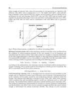
Example 9: Histogram Showing Thickness Distribution of 90 Cadmium-Plated
Components.
The small cylindrical part shown in Fig. 10 was plated in a horizontal barrel. The load contained about 5000 pieces.
Thickness of plate was measured with a magnetic gage on 90 parts from each load. Plating thickness ranged from 5 to 14
μm (200 to 560 μin.).
Fig. 10 Thickness distribution for cadmium plating of 90 samples that were evaluated from a 5000-
piece
production lot
Other Application Factors
Aside from considerations of cost of very large plating systems, there are no size limitations on parts that can be cadmium
plated, provided a tank of adequate size and other essential equipment are available. When a very large part is to be
plated, jet plating methods may sometimes be used, rather than constructing a very large plating tank. In the jet technique,
a steady stream of solution impinges against the part to be plated until the required thickness of plate is obtained. Because
of the rapid movement of the solution, very high current densities can be used. The quality of the plate is comparable to
that obtained by conventional methods.
Another technique that can be used on large parts is selective (or brush) plating. Detailed information is available in the
article "Selective Plating" in this Volume.
Hardness. The hardness of the basis metal has little or no effect on the successful deposition of cadmium. However, the
harder steels are likely to be more highly alloyed and may produce difficult-to-remove smuts from excessive pickling or
chemical cleaning. Pickling is also a source of hydrogen embrittlement, which may be particularly harmful to hardened
and stressed parts.
Springs often are electroplated with cadmium for protection against corrosion and abrasion. The following example
deals with failure of a cadmium-plated compression spring that was not properly treated to release hydrogen.
Example 10: Baking of Cadmium-Plated 6150 Alloy Steel to Eliminate Hydrogen
Embrittlement.
A spring used in a high-temperature relief valve under intermittent loading had dimensions and specifications as follows:
wire size, 8.76 mm (0.345 in.); outside diameter of spring, 50 mm (2 in.); length, 75 mm (3 in.); six coils; 6150 alloy steel
at 43 HRC; stress relieved immediately after coiling. The plating sequence was:
1. Alkaline clean.
2. Rinse in cold water.
3. Electroplate with cadmium 8 μm (320 μin.) thick.
4. Rinse in hot water.
5. Relieve hydrogen embrittlement in boiling water
1
2
h.
The spring broke with a shatter fracture typical of that caused by hydrogen embrittlement. The corrective action was to
bake the spring at 190 °C (375 °F) for 5 h.
For additional information on this subject, refer to the section "Hydrogen Embrittlement" in this article.
Service Temperature. Cadmium-plated, high-strength steel parts that are subjected to heavy loading should never be
used at temperatures above 230 °C (450 °F). Cadmium melts at 320 °C (610 °F); at temperatures approaching 260 °C
(500 °F), damage occurs that adversely affects mechanical properties.
Diffused Coatings. The aviation industry has developed an application for cadmium for low-alloy steel jet engine
parts. The substrate is first plated with 10 μm (400 μin.) of nickel and then 5 μm (200 μin.) of cadmium. The alloy is
diffused at 340 °C (645 °F) for about 1 h. Coverage with nickel must be complete, because cadmium can detrimentally
affect the steel substrate when heated above the melting point of cadmium. In this way, an alloy with a very high melting
point can be formed. Low-alloy steel parts that operate in jet engines at a temperature of 540 °C (1005 °F) were coated
with this diffused alloy. After operating for 1 h at 540 °C (1005 °F), the parts withstood 100 h of salt spray without
rusting. Cadmium can also be plated on copper and zinc, as well as on nickel.
Solderability. Although cadmium usually solders well with solders of the 60% tin, 40% lead type, using an inactive
rosin flux, its performance may sometimes be unaccountably erratic. Solderability can be improved and made more
consistent by predepositing a thin (3 to 4 μm, or 120 to 160 μin.) layer of copper. If the final cadmium deposit is at least 4
μm (160 μin.) thick, the copper coating will not adversely affect corrosion resistance in mild indoor atmospheres. It is
important for health and safety reasons to see the section "Toxicity of Cadmium" in this article.
Cadmium on Stainless. Cadmium can be successfully plated over stainless steels and heat-resisting chromium-nickel
alloys if the basis metal is first activated and given a light coating of nickel in a nickel chloride-hydrochloric acid bath
(U.S. Patent 2,437,409). Composition and operating conditions for this bath are as follows:
Factor Specification
Nickel chloride 240 g/L (32 oz/gal)
Hydrochloric acid (1.16 sp gr)
120 g/L (16 oz/gal)
Temperature Room temperature
Current density 55 to 2150 A/m
2
(50 to 200 A/ft
2
)
Time 2 to 4 min
Anodes Nickel
Plating of Cast Iron
Cast iron is difficult to plate because of the graphite flakes or nodules in the microstructure. The larger the graphite
inclusions, the more difficult the plating operation. Cast iron parts with unmachined surfaces should be cleaned by
mechanical methods, such as shot blasting or tumbling, before plating. Heavy pickling should be avoided if possible,
because it produces smut that is difficult to remove. However, light pickling is required after abrasive cleaning, to activate
the surface for plating.
Pickling should be followed by a thorough water rinse and a cyanide dip (see note in the table accompanying Fig. 4). Any
carryover of acid to the cyanide dip must be avoided, because the combination of these chemicals generates a highly
poisonous hydrocyanic gas. The fluoborate solution described in Tables 1(a) and 1(b) is excellent for plating cast iron
parts without deep recesses. The cyanide solutions in Tables 1(a) and 1(b) also may be used, provided no metal-organic
grain-refining agents have been added. Current density on the high side of the indicated ranges is recommended, to
establish a continuous film of cadmium on the iron as soon as possible.
Cadmium Versus Zinc
In rural areas, cadmium and zinc are generally considered to offer equal protection. However, zinc is superior to cadmium
in industrial environments (Table 9). In uncontaminated marine atmospheres, zinc and cadmium give approximately equal
protection. When the comparison is made at a distance of 24 m (80 ft) from the ocean, cadmium gives significantly
greater protection than zinc. Although it is used to a limited extent in the paper and textile industries, cadmium plate has
poor resistance to chemicals commonly used in these processes and also to the chemicals of the petroleum and
pharmaceutical industries.
Table 9 Protection against rusting imparted to steel in selected atmospheres by 25μm (1000μ
in.) of
cadmium plate or zinc plate
Time required
for 5 to 10%
rusting, yr
Test
location
Atmosphere
Cadmium
Zinc
New York, NY Industrial 2 4
Pittsburgh, PA Industrial 3 4
Sandy Hook, NJ Marine, Industrial
6 5
State College, PA
Rural >11 >11
Key West, FL Marine >7 >9
Source:ASTM
One reason for preferring cadmium to zinc is that cadmium plate forms a smaller amount of corrosion products than zinc,
particularly in marine atmospheres. Cadmium also retains its initial appearance for a longer time. This is an important
consideration in applications where a buildup of corrosion products would have a detrimental effect, such as preventing
the flow of current in electrical components or the movement of closely fitting parts such as hinges. For such applications,
cadmium should be chosen in preference to zinc. Cadmium is preferable to zinc for plating cast iron.
Cadmium Substitutes
There is increased pressure, both domestically and internationally, for reduced usage, or even elimination of cadmium
plating for health, safety, and environmental reasons. There have been several zinc alloy baths developed that work for
specific applications, but none duplicates all the properties of cadmium. There are many instances, however, where the
use of cadmium plating is not essential and zinc or zinc alloy deposits could be substituted, because both give adequate
anodic protection, and there was no functional purpose when cadmium was chosen in the first place.
Chemical Analysis of Cyanide Cadmium Plating Baths
Table 10 lists analytical tests that may be applied to cyanide cadmium plating baths to determine their contents of
cadmium metal, sodium cyanide, sodium hydroxide, and sodium carbonate.
Table 10 Analytical tests for determining concentration of selected chemical constituents of cyanide
cadmium plating baths
Component Test
constituent
Cadmium metal Sodium cyanide (total) Sodium
Hydroxide
Sodium Carbonate
Reagents Hydrochloric or sulfuric acid (concentrated)
Ammonium hydroxide (concentrated)
Eriochrome black "T" indicator (0.5% solution in
alcohol)
Formaldehyde (8% solution in water)
Ammonium hydroxide
(concentrated)
Potassium iodide (10%
solution in water)
Silver nitrate (13 g/L, or
LaMotte sulfo-
orange
indicator
Sulfuric acid,
standard (0.94
Barium chloride
(10% solution in
water)
Methyl orange-
xylene cyanole
Disodium dihydrogen ethylenediaminetetraacetate
dihydrate (EDTA), 0.575M solution (21.4 g/L, or
2.85 oz/gal)
1.7 oz/gal solution in
water)
N) indicator solution
Hydrochloric acid,
standard (0.7 N)
Procedure 1. Pipette exactly 2 mL (0.07 oz) of plating bath into
a 250 mL (8.5 oz) Erlenmeyer flask, and dilute to
about 100 mL (3.4 oz) with distilled water.
2. Neutralize this dilution to a faint white precipitate
with hydrochloric or sulfuric acid. This can be
conveniently done from the burette of standard
sulfuric acid (0.94 N used for the caustic titration, or
by the addition of a 50% solution of hydrochloric
acid from an eyedropper. If no precipitate appears,
as may happen with a new bath, thymolphthalein can
be used as an indicator and will change from blue to
colorless on neutralization.
3. Add 10 mL (0.34 oz) of concentrated ammonium
hydroxide and about
3
4
mL of Eriochrome indicator.
4. Zero the burette.
5. Add 8 mL (0.27 oz) of 8% formaldehyde solution.
6. Titrate immediately with EDTA solution. The
color change is from red to blue, and it is sharpest
when the solution is titrated as soon as possible after
the formaldehyde has been added. A rapid titration
will also give a sharper end point. Occasionally, the
presence of impurities in the bath will prevent the
attainment of a clear blue end point, but the color
will prevent the attainment of a clear blue end point,
but the color change is still sharp, from a red to a
purplish blue.
1. Pipette a 2 mL (0.07
oz)sample of plating
bath into a 250 mL (8.5
oz) flask.
2. Add to the sample
about 50 mL (1.7 oz)
distilled water, 5 to 7
mL (0.17 to 0.24 oz) of
ammonium hydroxide,
and 2 to 3 mL (0.07 to
0.10 oz) of potassium
iodide solution.
3. Titrate with silver
nitrate solution to the
first stable faint
yellowish turbidity.
1. Pipette 10
mL (0.34 oz)
of the plating
bath into a 250
ml (8.5 oz)
flask.
2. Add to the
sample about
1
2
mL (0.017
oz) of indicator
solution.
3. Titrate with
the sulfuric
acid to the
color change
from orange to
yellow.
1. Pipette 10 mL
(0.34 oz) of plating
bath into a 250 mL
(8.5 oz) beaker, add
to it about 100 mL
(3.4 oz) of water,
and heat to boiling.
2. Stir into boiling
bath dilution about
20 mL of barium
chloride solution;
cover mixture; allow
to stand warm for
about
1
4
to
1
2
h.
3. Filter, using No.
41 Whatman filter
paper, and wash
precipitate and flask
at least 2 or 3 times
with hot distilled
water.
4. Place paper and
precipitate in the
original beaker, add
about 10 mL (0.34
oz) of hot distilled
water and 3 or 4
drops of indicator.
5. Titrate with the
hydrochloric acid
(while stirring) to
the first permanent
color change from
green to purple.
Calculation Milliliters of EDTA solution used × 0.432 = ounces
per gallon, cadmium metal
Milliliters of silver
nitrate used × 0.5 =
ounces per gallon, total
sodium cyanide
Milliliters of
sulfuric acid
used × 0.5 =
ounces per
gallon, sodium
hydroxide
Milliliters of
hydrochloric acid
used × 0.5 = ounces
per gallon, sodium
carbonate
Methods for Measuring Thickness of Cadmium Plate
There are many nondestructive and destructive methods for measuring the thickness of cadmium deposits (Table 11). The
most widely used are magnetic, coulometric, and eddy-current methods, as well as x-ray spectrometry and microscopic
cross-sectioning. Other reliable methods, including the chemical drop test, may be used. Detailed information on most
methods can be obtained from ASTM specification B 659-85 ("Standard Guide for Measuring Thickness of Metallic and
Inorganic Coatings") (Ref 1) and ISO Standards.
Table 11 Methods applicable to measuring cadmium coating thickness on selected ferrous and nonferrous
substrates per ASTM B 659
Substrates Measurement technique
Beta backscatter
(a)
Coulometric
(b)
Magnetic
(c)
Magnetic steel (including corrosion-resisting steel) X X X
Nonmagnetic stainless steels X X . . .
Copper and alloys X X . . .
Zinc and alloys X . . . . . .
Aluminum and alloys X X . . .
Magnesium and alloys X . . . . . .
Nickel X X . . .
Glass sealing nickel-cobalt-iron alloys (UNS No. K94610)
X . . . X
Nonmetals X X . . .
Titanium X . . . . . .
Source: Ref 1
(a)
ASTM B 567; ISO 3543.
(b)
ASTM B 504; ISO 2177.
(c)
ASTM B 499; ISO 2178.
Reference cited in this section
1.
1989 Annual Book of ASTM Standards, Vol 2.05
(Metallic and Inorganic Coatings; Metal Powders,
Sintered P/M Structural Parts), ASTM, 1989, p 441-443
Solutions for Stripping Cadmium Plate
Electrodeposited cadmium can be stripped chemically from the basis metal by immersion in one of the following
solutions: ammonium nitrate, inhibited hydrochloric acid, chromic acid with a sulfuric acid addition, and ammonium
persulfate with an ammonium hydroxide addition. Electrolytic stripping is performed in a solution of sodium cyanide with
an addition of sodium hydroxide. Compositions of these stripping solutions, and the immersion times to be used with
them, are given in Table 12.
Table 12 Solutions for stripping electrodeposited cadmium
Amount Solution
(a)
Composition
g/L oz/gal
Immersion
time, min
(b)
1 Ammonium nitrate 105-136
14-18
10-20
Hydrochloric acid (1.18 sp gr), undiluted
. . . . . . 10-20 2
(c)
Antimony trioxide 15 2 . . .
Chromic acid 203 26.8 5-10 3
Sulfuric acid (95%) 48
(d)
6.4
(e)
. . .
Ammonium persulfate 51 6.7 5-10 4
Ammonium hydroxide 96.8
(d)
12.8
(e)
. . .
5
(f)
Sodium cyanide 60-91 8-12 10-20
(a)
Solutions are listed in order of preference; all solutions are used at room temperature.
(b)
Immersion times are for deposits 8 to 13 μm (320 to 520 μin.) thick.
(c)
Solution should not be used on stressed or hardened parts.
(d)
mL/L.
(e)
fl oz/gal.
(f)
Solution for stripping electrolytically; 540 to 1080 A/m
2
(50 to 100 A/ft
2
) and 6 to 8 V; part to be stripped is made the
anode.
Toxicity of Cadmium
Two hazardous consequences attend the use of cadmium in contact with food products: acute poisoning resulting from the
ingestion of cadmium dissolved from containers or from food-handling equipment; and poisoning from the inhalation of
fumes of cadmium oxide, if cadmium-plated vessels or food-handling equipment is heated.
Acute poisoning has resulted from the ingestion of cadmium salts derived from cadmium-plated vessels in which any acid
foods have been stored for even short periods of time; therefore, cadmium should not be used on food containers of any
kind. Fatal poisoning is more apt to result from the inhalation of dust or fumes of cadmium salts and cadmium oxide.
These are the kinds of exposure encountered in industrial operations when cadmium-plated parts are heated or soldered.
Exposure to dust or fumes of cadmium should be avoided and safety / OSHA regulations should be followed. The
complete regulatory text of the cadmium rule and appendixes is published in the Federal Register 57 (178): 42102-42463,
14 September 1992. Among its provisions, the rule requires employers to adhere to a new personal exposure limit (5 g/
μm
3
), provide medical surveillance, monitor exposure level, and maintain proper records.
Deposits of cadmium on the sides or bottom of a tank previously used for cadmium plating should not be burned off,
because the fumes from this operation are highly toxic. These deposits should be removed mechanically or deplated. For
high-efficiency deplating, the solution used contains 45 to 60 g/L (6 to 8 oz/gal) of sodium cyanide and 23 to 30 g/L (3 to
4 oz/gal) of sodium hydroxide in water; the tank is the anode, and steel sheets or scrap steel parts are the cathodes. Just
like the production solutions presented in Table 1(a), the resulting solution must be treated with the utmost care. The
proper handling of cyanide solutions should be discussed with the proper vendors, and internal safety departments must
train operators in the safe use of these solutions. Disposal issues must be part of waste treatment management practices.
Additional information is available in the article "Cadmium Elimination" in this Volume.
Selective Plating
When plating must be applied to only certain areas of parts, the areas not to be plated must be stopped off or masked,
which means they must be covered with materials that will not conduct current, such as waxes, lacquers, or rubber tape.
Waxes. Ordinarily, a petroleum-derived wax is used for stopping off. The wax must not contain any oil or other organic
materials that will dissolve in the plating solution and contaminate it. It must also be capable of adhering tightly to the
part, to prevent the plating solution from coming in contact with the stopped-off area.
Before being applied, the wax is heated in a pot to about 27 °C (80 °F) above its melting point, so that it does not solidify
too rapidly and will adhere more readily. Still-better adhesion is obtained if parts are warmed on a hot plate before the
wax is applied.
Parts must be positioned so that only the area to be coated is placed in the molten wax. This means that, normally, only
end areas or protrusions can be stopped off with wax. The wax can be applied with camel's hair brushes, but this is time-
consuming if many parts are to be treated. For a large number of similar parts, a fixture can be used that will dip each part
to the proper depth.
A sharp, uniform demarcation between plated and nonplated areas can be obtained by the use of pressure-sensitive tape
and wax, following either of two procedures:
•
Apply the tape to the part so that the trailing edge of the tape follows the demarcation line; dip that
portion of the part to be left unplated in molten wax so as to overlap the trailing edge of the tape
slightly; and then remove the wax when it has solidified.
•
Apply the tape to the part so that the leading edge follows the demarcation; dip that portion of the part to
be left unplated in molten wax so as to overlap partly the trailing edge of the tape; and t
hen, when the
wax has solidified, plate the part without removing the tape.
Waxing must be done carefully, so that areas that are to be plated have no wax on them. If wax does get on areas to be
plated, it must be thoroughly removed. After plating and postplating treatments, the wax is removed from parts by placing
them in hot water.
Lacquers may be used instead of wax as stop-off coatings, but their use is generally limited to instances in which the
plating bath is operated at a temperature at which the wax would melt. Lacquer is applied by dipping or painting the areas
to be stopped off. Normally, two to four coats of lacquer must be applied. One disadvantage of lacquer is that it is difficult
and time-consuming to get all of it off. Heavier coatings prevent leakage and make stripping easier.
Plastic Tape. For stopping off irregular areas of heavy parts that cannot be dipped or that are too large to be painted
(e.g., splines, large shafts, or bearing shoulders), a plastic tape is used. The tape is wound tightly and stretched over the
irregular areas. To prevent leakage, each turn should overlap the preceding one at least half-way. At the edge of the stop-
off area, a pressure-sensitive tape is used to form a sharp line and prevent the leakage of plating solution under the plastic
tape.
Plastic tape is expensive to use. When many similar parts are to be selectively plated, rubber sheet, held in place by
pressure-sensitive tape, may be used for stopping off areas not to be plated. Rubber stoppers, plastic plugs, or corks,
sealed with wax, are used for stopping off internal areas of cylindrical parts. Rubber or plastic tubing can be used to stop
off areas of small cylindrical parts.
Rinsing and Drying
Although one of the simplest operations in plating, rinsing is often the most difficult to accomplish. The primary
requirements are that the rinsing be effective in removing the solutions used in the preceding tank and that no
contaminants be introduced into the subsequent tank. Rinse baths, whether hot or cold, usually are provided with some
means for constant changing of the water, good agitation, and skimming of the surface. Agitation of both the water and
part is usually necessary. The surface skimmer may consist of jets of water shooting across the surface to rinse surface
films into an overflow trough at the far side of the rinse tank. Water should enter at the bottom of one side of a rinse tank
and escape over a weir outlet along the top at the opposite side of the tank. Constant monitoring of the water quality
versus product quality is essential with the increased demand to lower water usage. The amount of contamination in rinse
tanks can be regulated by controlling the flow of fresh water into the rinse through a valve actuated by a conductivity cell.
The temperature of the postplating rinse bath depends to some extent on the mass of the work being rinsed, because the
workpiece must supply all the heat of evaporation for drying. Thin-gage materials require rinse temperatures of 93 to 100
°C (200 to 212 °F); otherwise, the workpiece cools before evaporation is complete. Parts made from thicker materials
may be rinsed in water at 82 to 88 °C (180 to 190 °F).
Rapid and thorough drying of the plated work is important, to prevent water marks and stains and to eliminate the
moisture from residual salt that may not have been entirely removed from crevices or recesses by rinsing. Residual salt
and moisture can be a source of corrosion.
Drying practice is also influenced by the shape and orientation of the workpiece as it leaves the final rinse. In many
applications, hot-water rinsing is followed with oven drying, wherein hot air is blown directly against the work. In
automatic installations, oven temperatures are maintained at 105 °C (220 °F) or higher and the work passes through in 3
to 5 min. Centrifuges with a hot air blast are used for barrel-plated work.
Hydrogen Embrittlement
If an electrodeposited coating is to be applied to a highly stressed part or a high-strength (over 1100 MPa, or 160 ksi)
heat-treated steel part, it is important that the processing not decrease the static or fatigue strength of the part. Hydrogen
embrittlement does not affect fatigue life. Coatings having high residual stresses, such as chromium, affect fatigue life;
however, this is not the case with cadmium.
Cadmium deposited from a cyanide solution is more likely to produce hydrogen embrittlement than any other commonly
plated metal. Heat-treated steels, particularly those plated and used at 35 HRC and above, are susceptible to hydrogen
embrittlement. Most susceptible is spring steel that has not been adequately stress relieved after forming. The
requirements of Federal Specification QQ-P-416F may be used as a guide for stress relief before plating and hydrogen
embrittlement post-treatment (Table 13). Other guidelines vary from these, but the latest revision (F) seems to be the most
stringent.
Table 13 Heat treat specifications required to stress relieve cadmium-plated components
Stress relief before plating Hydrogen embrittlement relief (within 4 h of plating)
Temperature Temperature
Hardness, HRC
°C °F
Minimum time,
h
°C °F
Minimum time,
h
34-54 175-205
350-400
4 . . . . . . . . .
36-45 . . . . . . . . . 175-205 350-400 8
23
(a)
46-54 . . . . . . . . . 175-205 350-400 23
>55 120-150
250-300
23 120-150 250-300 23
(a)
Fasteners and bearings
Although the thickness of the plated deposit appears to have no direct bearing on hydrogen embrittlement, it is always
more difficult to release the hydrogen (by baking) from heavy deposits.
By adhering to the following procedures, hydrogen embrittlement can be minimized or made inconsequential:
• Use mechanical cleaning methods, such as brushing, blasting, and tumbling.
• Wherever possible, avoid the use of strong acid-
pickling solutions and extended exposure to acid
pickling.
• If pickling is essential to the preparation of medium-strength and high-
strength steel parts, bake the parts
at 175 to 205 °C (350 to 400 °F) for 3 h after pickling and before plating.
• In plating, use the higher current densities to produce a more porous deposit; 755 A/m
2
(70 A/ft
2)
in a
cyanide bath without brighteners has been satisfactory for steel at 46 HRC.
• After plating, bake parts at 175 to 205 °C (350 to 400
°F) for 3 to 24 h. The shorter baking periods are
generally adequate for parts with a tensile strength below about 1520 MPa (220 ksi); longer baking
periods are recommended for steel of tensile strength above about 1520 MPa (220 ksi) or for lower-
strength
parts if sharp notches or threads exist. Parts greater than 25 mm (1 in.) thick should also be
baked for 24 h. The elapsed time between plating and baking must never exceed 8 h and should be
carried out as soon as possible, preferably within 4 h.
• Plate parts to a thickness of about 5 μm (200 μ
in.), bake for 3 h at 195 °C (385 °F), activate in cyanide,
and then complete the plating to the required final thickness.
The applications of shot peening and baking, as related to the hardness of the steel to be plated, are described in Federal
Specification QQ-C-320 (Amendment 1) and are summarized in the article "Industrial (Hard) Chromium Plating" in this
Volume.
Tests for Adhesion of Plated Coatings
The tests used for evaluating adhesion of plated coatings are largely qualitative. A bend test, described in Federal
Specification QQ-P-416, involves observation of the degree of flaking that occurs as a specimen is bent. Additional tests
are scrape/scratch, short blasts from a glass bead machine (reduced pressures), and bake/cold water quench, all of which
tend to show blistering or peeling. In another test, a pressure-sensitive tape, such as surgical adhesive or masking tape, is
attached to the plated surface. The tape is quickly stripped from the specimen by pulling it at right angles to the surface. If
adhesion is poor, loose plate or blisters will appear as flecks on the surface of the adhesive.
Another good test for adhesion, on parts that have been baked after being plated, is a visual inspection for blisters in the
plate. If a good bond has not been established, the plate will most often pull away from the basis metal and form blisters.
Chromate Conversion Coatings
The corrosion of cadmium plate can be retarded by applying a supplemental chemical conversion coating of the chromate
type. The chromate films are produced by immersing the plated article in a solution containing chromic acid or other
chromates and catalytic agents. These films provide protection against initial corrosion through the inhibitive properties
of the water-soluble chromium compounds present. However, the chromate finish must not be applied before stress
relieving or baking, because its beneficial effect will be destroyed by the elevated temperature.
Chromate conversion coatings are used in some instances to improve the bond between paint and cadmium-plated
surfaces and to provide the plate with resistance to corrosion if gaps should occur in the paint film. However, wash
primers will not adhere to chromate finishes, and baking painted chromate finishes will produce poor bonding.
Plate Discoloration. Cadmium tarnishes easily from handling and, at a lesser rate, from normal oxidation. Both types
of tarnish may be prevented by the use of chromate conversion coatings. For maximum prevention of tarnish, an
unmodified chromate film should be applied, if the iridescence or the light yellow coloration it imparts is not
objectionable. Such a surface film also provides resistance against salt spray and humidity, and its application for this
purpose is frequently standard practice. The clear film obtained by bleaching a chromate coating affords much poorer
protection, but it is superior to an as-plated cadmium surface with respect to resistance to tarnishing, humidity, and salt
spray.
With a plate thickness of 13 to 18 μm (520 to 720 μin.) and a chromate conversion coating, cadmium will provide
adequate service in marine and humid tropical atmospheres. When long-term exposure is anticipated, a paint coating is
desirable.
If a chromate treatment is used, only two cold-water rinse tanks are necessary after plating. The first may be for
reclaiming the cadmium solution or for the treatment of water. The second rinse should be provided with sufficient flow
and agitation to prevent carryover of cyanide into the chromate solution. After chromate dipping, three rinse tanks are
required. Again, the first tank may be for reclaiming or waste treatment.
Yellow chromate finish is obtained by dipping in acidified sodium or potassium dichromate. Excellent corrosion
protection and a superior base for organic finishing are obtained.
Clear chromate finish consists of 117 g (0.258 lb) of chromic acid and 1.2 g (2.6 × 10
-3
lb) of sulfuric acid per liter
(gallon) of water and provides good passivation and attractive appearance. Although the protective film is very thin, it
prevents the formation of a white, powdery corrosion product on cadmium-plated parts in indoor or internal-component
use.
Olive green coating is obtained in an acidified dichromate solution and is easily colored by any of the acid dyes.
Other Postplating Processes
Bright Dipping. The solution for bright dipping consists of
1
4
to 1% of commercial-grade nitric acid (1.41 sp gr) and is
used at room temperature. The acid neutralizes any alkaline salts on the surface and provides some passivation. It is used
extensively because it does not interfere with solderability. Immersion times vary from 2 to 30 s.
A solution of acidified hydrogen peroxide is also used for bright dipping. It consists of 6 to 7% commercial-grade (35%)
hydrogen peroxide acidified with about 0.25% H
2
SO
4
. It produces a bright luster and uniform finish but adversely affects
resistance to atmospheric corrosion, ultimately resulting in the formation of a white powder. The solution is rather
expensive and has a short life.
Phosphate treatment produces a supplementary conversion coating. The solution consists of 3 to 4% equivalent
phosphoric acid at a pH of 3.5 to 4.2. The solution is maintained at a temperature of 71 to 88 °C (160 to 190 °F);
immersion time ranges from 3 to 5 min. Following the acid dip, parts are water rinsed and then passivated for 2 to 3 min
in a solution of sodium dichromate (0.8 to 1.5 g/L, or 0.1 to 0.2 oz/gal) or chromic acid (pH, 3.5 to 4.0) at a temperature
of 66 to 77 °C (150 to 170 °F). The coating provides a good basis for organic finishes.
Molybdenum coating is performed in a proprietary bath containing molybdenum salts dissolved in a highly
concentrated solution of ammonium chloride at 54 to 66 °C (130 to 150 °F). An attractive, adherent black finish is
obtained.
Zinc Plating
Revised by A. Sato, Lea Ronal Inc.
Introduction
ZINC is anodic to iron and steel and therefore offers more protection when applied in thin films of 7 to 15 μm (0.3 to 0.5
mil) than similar thicknesses of nickel and other cathodic coatings, except in marine environments where it is surpassed
by cadmium (which is somewhat less anodic than zinc to iron and steel). When compared to other metals it is relatively
inexpensive and readily applied in barrel, tank, or continuous plating facilities. Zinc is often preferred for coating iron and
steel parts when protection from either atmospheric or indoor corrosion is the primary objective. Electroplated zinc
without subsequent treatment becomes dull gray in appearance after exposure to air. Bright zinc that has been
subsequently given a chromate conversion coating or a coating of clear lacquer (or both) is sometimes used as a
decorative finish. Such a finish, although less durable than heavy nickel chromium, in many instances offers better
corrosion protection than thin coatings of nickel chromium, and at much lower cost.
Much recent attention has been focused on the development of techniques for electroplating alloys such as zinc-iron, zinc-
nickel, and zinc-cobalt. The operating parameters and applications of these coatings is very similar to those for unalloyed
zinc. More detailed information about these techniques is provided in the article "Zinc Alloy Plating" in this Volume.
Plating Baths
Commercial zinc plating is accomplished by a number of distinctively different systems: cyanide baths, alkaline
noncyanide baths, and acid chloride baths. In the 1970s, most commercial zinc plating was done in conventional cyanide
baths, but the passage of environmental control laws throughout the world has led to the continuing development and
widespread use of other processes. Today, bright acid zinc plating (acid chloride bath) is possibly the fastest growing
system in the field. Approximately half of the existing baths in developed nations use this technology and most new
installations specify it.
The preplate cleaning and postplate chromate treatments are similar for all zinc processes; however, the baths themselves
are radically different. Each separate system is reviewed in detail in this article, giving its composition and the advantages
and disadvantages.
Cyanide Zinc Baths
Bright cyanide zinc baths may be divided into four broad classifications based on their cyanide content: regular cyanide
zinc baths, midcyanide or half-strength cyanide baths, low-cyanide baths, and microcyanide zinc baths. Table 1 gives the
general composition and operating conditions for these systems.
Table 1 Composition and operating conditions of cyanide zinc baths
Standard cyanide bath
(a)
Mid or half-strength cyanide bath
(b)
Optimum Range Optimum Range
Constituent
g/L oz/gal
g/L oz/gal g/L oz/gal g/L oz/gal
Preparation
Sodium cyanide 42 5.6 30-41 4.0-5.5 20 2.7 15-28 2.0-3.7
Sodium hydroxide 79 10.5 68-105
9.0-14.0 75 10.0 60-90 8.0-12.0
Sodium carbonate 15 2.0 15-60 2.0-8.0 15 2.0 15-60 2.0-8.0
Sodium polysulfide 2 0.3 2-3 0.3-0.4 2 0.3 2-3 0.3-0.4
Brightener
(g)
(g)
1-4 0.1-0.5
(g)
(g)
1-4 0.1-0.5
Analysis
Zinc metal 34 4.5 30-48 4.0-6.4 17 2.3 15-19 2.0-2.5
Total sodium cyanide
93 12.4 75-113
10.0-15.1
45 6.0 38-57 5.0-7.6
Sodium hydroxide 79 10.5 68-105
9.0-14.0 75 10.0 60-90 8.0-12.0
Ratio: NaCN to Zn 2.75
0.37 2.0-3.0
0.3-0.4 2.6 0.3 2.0-3.0 0.2-0.4
Low-cyanide bath
(c)
Microcyanide bath
(d)
Optimum Range Optimum Range
Constituent
g/L oz/gal
g/L oz/gal g/L
oz/gal
g/L oz/gal
Preparation
Zinc cyanide 9.4
(b)
1.3
(e)
7.5-14
(b)
1.0-1.9
(f)
(f)
(f)
(f)
Sodium cyanide 7.5 1.0 6.0-15.0
0.8-2.0 1.0
0.1 0.75-1.0
0.4-0.13
Sodium hydroxide 65 8.7 52-75 6.9-10.0
75 10.0 60-75 8-10
Sodium carbonate 15 2.0 15-60 2.0-8.0 . . .
. . . . . . . . .
Sodium polysulfide . . . . . . . . . . . . . . .
. . . . . . . . .
Brightener
(g)
(g)
1-4 0.1-0.5
(g)
(g)
1-5 0.1-0.7
Analysis