The Welding of Aluminum & Its Alloys Part 10 doc
Bạn đang xem bản rút gọn của tài liệu. Xem và tải ngay bản đầy đủ của tài liệu tại đây (279.16 KB, 20 trang )
surface indentation can be readily identified. These features may be used
to assess the quality of production batches.
9.5 Seam welding
Seam welding uses a wheel-shaped electrode (Fig. 9.4) to make either a
series of overlapping spot welds to form a continuously welded and leak
tight seam or a number of spot welds spaced apart – roll-spot welding. The
requirements on electrodes and surface finish are the same as for spot
welding. The shunt effect of the closely spaced nuggets and the short weld
times mean that higher currents are necessary than for spot welds. Typical
welding parameters are given in Table 9.4.
Higher welding forces will be needed for harder alloys and lower values
for softer alloys. Welding parameters for three phase frequency converter
Resistance welding processes 175
9.4 Typical resistance seam welder showing the copper wheel
electrodes. Courtesy of British Federal.
units are similar to those in Table 9.4 except that welding current needs to
be increased by between 0.5 and 2.5 times, the higher values for the thicker
materials.
Pick-up on the electrode wheel can be a problem and may require the
wheel to be cleaned after only one revolution. Mechanised cleaning systems
that remove the contamination in-process by wire brushing or abrasive
means have been successful in maintaining continuous production.
9.6 Flash butt welding
9.6.1 Process principles
As the name suggests flash butt welding is capable of making butt joints in
bar-like or tubular components, L,T and X-shaped extrusions, etc.The weld
is a solid phase joint where the two ends of the component are forged
together at high temperature, any molten metal being expelled from
between the two faces (Fig. 9.5). The process takes place in two phases, a
‘flashing’ and an upsetting phase. The two components to be joined are
clamped in electrodes, at least one of which is movable.A low-voltage, high-
amperage current is applied without the two components being in contact.
The parts are then brought together at a controlled rate, resulting in a series
of brief short-circuits as the asperities on the faying faces melt and burn off.
This continuous series of short-circuits raises the temperature of the ends
and expels some of the molten metal, giving the ‘flashes’ that give the
process its name.
The heating melts and plasticises the metal and, once sufficient heat has
been built up, the ends of the components are forged together, forcing out
any melted metal, oxides and contaminants and some of the plasticised
material, forming a ‘flash’ or ‘upset’. The expulsion of contaminants and
176 The welding of aluminium and its alloys
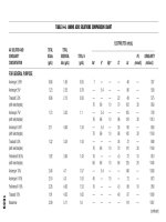
Table 9.4 Seam welding conditions. Single phase AC units. Hardened 5XXX
series alloy
Sheet Travel Spots/ On plus On time Welding Welding Weld
thickness speed metre off time (cycles) current force
(mm) (m/min) (cycles) (kA) (kN)
0.9 1.02 625 5 1.0 29.0 3.1 3.2
1.0 0.88 550 7 2.0 32.0 3.4 3.5
1.6 0.79 395 10 3.0 38.5 4.3 4.8
2.0 0.64 355 12.5 4.0 41.0 4.8 5.5
2.5 0.55 315 18 5.5 43.0 5.5 6.5
3.2 0.45 275 24 7.0 45.0 6.0 8.0
Resistance welding processes 177
9.5 Principles of flash butt welding. Courtesy of TWI Ltd.
oxides means that pre-weld cleanliness is not as important as the conven-
tional fusion welding processes. The weld is consolidated by this forging
action, giving a high-strength joint even in heat-treatable alloys.The forging
action also eliminates any cast structure and reduces the width of the HAZ.
A monitor chart from a typical weld sequence is illustrated in Fig. 9.6.
9.6.2 Welding machines
The basis of the flash welding machine is an AC transformer, the majority
of production equipment being single phase machines. The electrodes or
clamps are mounted on two rigid platens, at least one of which is movable
and powered by a pneumatic or hydraulic system (Fig. 9.7). The capacity of
the machine is limited by the current requirements of the joint and the upset
pressure available. The power demanded of the transformer is based on
the cross-sectional area of the faying faces as a critical current density is
required. The varying electrical conductivity of the different alloys also has
an effect on power requirements and the range of yield strengths place
varying demands on the upset pressure mechanism. As an approximation a
machine capable of flash butt welding 65cm
2
of steel can weld only some
35cm
2
of aluminium.
The current requirements for flash butt welding range from around
12500 to 15500A/cm
2
during the upset phase of welding. Current
requirements during the flashing stage will be some 30–50% less than the
upset current. Voltages vary from 2 volts at a low cross-sectional area to 20
volts for the thicker sections. The lowest voltage possible should be used
consistent with stable flashing for the best results.
178 The welding of aluminium and its alloys
2
1
3
9.7 Schematic of a typical tube or bar flash welding machine.
1 = current sensing circuit 2 = upset control 3 = pressure transducer.
Upset length
Upset force
Movement
Force
Flashing length
Flashing Upset
9.6 Typical monitor chart – flash butt welding of cylinder rims.
9.6.3 Electrode clamps
For the welding of steel copper alloys are generally used for the manufac-
ture of the electrode clamps. For aluminium, however, steel, sometimes
copper plated, has been found to give better results, conducting less heat
away from the weld, providing a longer life and more positive clamping. By
drawing the weld back through one of the clamps fitted with a knife edge
it is also possible to shear off the upset as part of the removal process. A
broach may be inserted into the bore of hollow components to remove any
internal flash. To achieve a clean cut and to prevent smearing of the upset
during removal the cutting edges must be kept sharp. The clamps are
machined to match the outside shape of the components and are split to
enable rapid insertion. They are also designed to clamp around 80% of the
circumference and to be of a sufficient length that slippage does not occur
during upsetting.
To prevent crushing or deformation of hollow components removable
inserts or backing devices may be used beneath the clamp area. Sufficient
distance must be left between the ends of the inserts to ensure that they do
not take part in the welding operation.
9.6.4 Quality control
Provided that the equipment is correctly set-up and maintained, flash butt
welding is a trouble-free process. Alignment of the components is vital to
achieve low rates of weld rejects. Failure to align the components can result
in ‘shelving’ where one component rides up over its partner and in uneven
flashing, producing lack of fusion defects. Insufficient heat and/or inade-
quate upset may both result in lack of fusion type defects or oxide entrap-
ment. Both of these defects can be readily detected by the use of a bend
test such as those required by the procedure approval specification BS EN
288 Part 4 – see Chapter 10, Table 10.3. Bend testing is a relatively inex-
pensive method of assuring weld quality. Those non-destructive test tech-
niques that are commonly used for interrogating arc-welded butt joints,
such as radiography or ultrasonic examination, are not suitable for flash
butt welding and the engineer is forced to consider destructive tests. Bend
testing of pre-production test pieces prior to the start and at the end of a
production period of some 8 hours is one of the most cost-effective and
easily performed techniques. When this testing is supplemented by in-
process monitoring of the welding parameters (Fig. 9.6) then it is possible
to demonstrate a 100% acceptable weld quality. While it is written for the
control of steel flash butt welding the specification BS 4204 ‘Flash Butt
Welding of Steel Tubes for Pressure Applications’ is an extremely useful
reference, full of information that may be applied to aluminium alloys. It
Resistance welding processes 179
gives recommendations on equipment choice, welding sequence control,
procedure approval testing and production control testing.In addition there
is an example of a flash welding weld procedure record form and a list of
information required on a weld procedure specification.
180 The welding of aluminium and its alloys
10.1 Introduction
Very often the decisions on how a weld should be made, filler metal and
welding parameter selection are left to the welder. While this may be
acceptable in those situations where the weld quality is only incidental to
the integrity of the fabrication it is not acceptable where the weld is crucial
to the performance of the component. The need for approved welders to
work to approved welding procedures is also often a requirement of either
the application standard to which the fabrication is designed and con-
structed or a contract specification requirement. Aside from these specifi-
cation requirements it may be necessary for the fabricator to be able to
demonstrate to clients, to regulatory authorities or, should a failure leading
to loss or damage occur, to a court of law that the welds have been made
to an acceptable quality.To specify how both the welds and the welders may
be shown to be acceptable there are a number of standards available to the
engineer. The requirements of some of these standards are covered in this
chapter.
It cannot be emphasised too strongly that the detail below is only a
summary of the specification requirements and must be treated with
caution. Although best efforts have been made to ensure that the abstracts
are accurate, they are only abstracts and accurate at the time of writing.
Where compliance is a standard or contract requirement the latest edition
of the approval standards must be consulted.
10.2 Welding procedures
A welding procedure or weld procedure specification (WPS) is a written
instruction that specifies materials, consumables and edge preparations for
a given joint. It lists the pre- and post-weld operations including heat treat-
ments; machining, grinding and dressing of the weld; details the welding
variables and the run sequence; and may specify the acceptance criteria and
10
Welding procedure and welder approval
181
inspection methods. The purpose of the WPS is to ensure that acceptance
criteria can be met consistently, including mechanical properties and defect
levels. It is also useful in enforcing quality control procedures, in standard-
ising on welding methods,production times and costs and in controlling pro-
duction schedules. Its prime purpose, however, is to give the welder clear,
unequivocal instructions on how a weld is to be made. A typical WPS is
shown in Fig. 10.1.
In order to confirm that the welding procedure, if followed, is capable
of providing the required strength and freedom from defects, the WPS is
approved or qualified. This approval is achieved by welding and testing
a test piece representative of the production welds, the welding details
and the test results being recorded in a weld procedure approval record
(WPAR). In the American ASME specifications this is known as a proce-
dure qualification record (PQR). Within the WPAR a number of essential
variables are identified. These essential variables are those features of the
procedure that, if changed outside a range of approval, will result in an
unacceptable change in the mechanical properties or defect level of the
weld, invalidating the WPS and making re-approval necessary.
The procedure approval specifications detail the acceptable forms of test
pieces, the essential variables and their ranges of approval, test methods
and acceptance standards. The most commonly encountered specifications
are the European specifications, the EN 288 series and the American
specifications, the ASME codes.
10.2.1 The BS EN 288 specifications for arc
welding approval
The EN series are all entitled ‘Specification and Approval of Welding
Procedures for Metallic Materials’.
There are currently 9 parts of the EN specifications as follows:
• Part 1 General Rules for Fusion Welding.
• Part 2 Welding Procedure Specification for Arc Welding.
• Part 3 Welding Procedure Tests for the Arc Welding of Steel.
• Part 4 Welding Procedure Tests for the Arc Welding of Aluminium and
its Alloys.
• Part 5 Welding Approval by Using Approved Welding Consumables for
Arc Welding.
• Part 6 Approval Related to Previous Experience.
• Part 7 Approval by a Standard Welding Procedure for Arc Welding.
• Part 8 Approval by a Pre-production Welding Test.
• Part 9 Welding Procedure Test for Pipeline Welding on Land and Off-
shore Site Butt Welding of Transmission Pipelines.
182 The welding of aluminium and its alloys
Welding procedure and welder approval 183
Manufacturer’s WPS number
WPAR number
Location
Manufacturer
Main welding process
Root welding process
Joint type
Welding position
TWI
IN ACCORDANCE WITH CLEANING
PROCEDURE CP015/AL
AIMg4, 5mNo.7
BS EN 573 PI2 AW5083
From 12 To 25
From >500 To
Rev. 02
Rev. 0
036/AL
/82/PL
005/AL
/82/PL
WORKS
ALWELD SERVICES LTD
131-MIG
131-MIG
Butt-plate ss mb
FLAT (PA)
Examiner or examining body
Method of preparation and
cleaning
Parent metal
Specification
Composition
Material thickness
Outside diameter
(mm)
(mm)
Joint design Welding sequence
Welding preparation details (sketch)*
Welding details
Welding details
Other information*
Examiner or examining bodyManufacturer
1 to FILL 131 MIG 1.6 325 TO 375 26 TO 31 DC + ve 400 TO 450
Run Process
Size of filler
metal
(mm)
Current
(Amps)
Voltage
(volts)
Type of current/
polarity
Wire feed
speed
(m/min)
Run-out length or
travel speed*
(mm) or (mm/min)
Heat input*
(KJ/mm)
70–75
degs
3 to 6
mm
12
mm
to
25
mm
1.5
mm max
backing strip 35 mm ¥ 10 mm thick
12
mm
to
25
mm
pass sequence
indicative only
1
2
3
5
4
6
7
METRODE ER5556
BS 2901 Pt 4 5556A
NA
99.995% PURE ARGON (DEW POINT < –
40C)
NA
26
NA
NA
A5083 BACKING STRIP 35
MM ¥ 10 MM THICK
10 MIN
200 MAX
NA
NA
NA
15
NA
NA
NA
NA
NA
Filler metal trade name
Filler metal classification
Baking or drying instructions
Gas or flux type:
Gas flow rate:
Tungsten electrode type/size
Details of back gouging/backing
Preheat temperature
Interpass temperature
Post weld heat treatment and/or ageing
Time, temperature, method
Heating and cooling rates*
Shielding:
Backing:
(l/min) Shielding:
(l/min) Backing:
(mm)
(°C)
(°C)
(mins, °C)
(°C/min)
Weaving (maximum width of run)
Oscillation: amplitude, frequency, dwell time
Pulse welding details
Distance contact tube/work piece
Plasma welding details
Torch angle
Notes
(mm)
(mm)
(deg.)
Name
*If required
Signature Name Signature
TWI
Date
08/Jan/2002
ALWELD SERVICES LTD
Date
03/Jan/2002
Weldspec 4.01.161 (c) Copyright 2002 C-spec/TWI Software. All rights reserved worldwide.
Page 1 of 1
Catalog n° WPS00019
ALWELD SERVICES LTD
Granta Park, Great Abington, Cambridge, CB1 6AL
EN288 – Manufacturer’s Welding Procedure Specification (WPS)
Weldspec for Windows
TWI
10.1 Example of welding procedure specification (WPS) prepared in
accordance with BS-EN 288 Part 4.
Of the 9 parts of the EN 288 specification only Parts 1, 2 and 4 are dealt
with in this review.
Part 1 contains definitions and discusses briefly the methods of approval
contained in Parts 3 to 8. It also requires WPSs to be prepared in accor-
dance with Part 2.
Part 2 specifies the requirements for the contents of welding procedure
specifications for arc welding, listing all of the variables that need to be
included and giving instructions as to how the weld shall be made. There is
also in Appendix A of the specification a copy of a suggested form for a
WPS. See also Fig. 10.1.
Part 4 is the most important part within the series with respect to
aluminium. It specifies how a WPS for the welding of aluminium or its alloys
shall be approved. It gives the limits of validity of the WPS within the
range of variables and includes an example of a WPAR and the accom-
panying approval certificate. Copies of these are included in Appendix
A of the specification. It lists the size and shape of the test pieces and the
non-destructive and mechanical tests required to prove the properties
of the weld. It covers TIG, MIG and plasma-arc welding processes only,
although it may be used as the basis for approving other processes by
agreement.
In order to reduce the number of tests required the alloys are formed
into groups, each group having similar characteristics as listed in Table 10.1.
The test pieces are representative of the joints to be welded in produc-
tion, comprising plate and pipe butt welds, branch welds and fillets. Test
piece sizes are illustrated in Fig. 10.2. The test piece form, type of test
and methods and extent of examination of the test pieces are detailed in
Table 10.2.
184 The welding of aluminium and its alloys
Table 10.1 Aluminium alloy grouping system
Group Type of alloy
21 Pure aluminium
Aluminium with less than 1.5% impurities, e.g. 1050, 1080, 1200, 1350
Aluminium with less than 1.5% alloy additions, e.g. 3103
22 Non-heat-treatable alloys divided into two groups:
22.1 Aluminium–magnesium alloys with 3.5% Mg or less, e.g. 3105, 5005,
5052, 5154, 5454
22.2 Aluminium–magnesium alloys with between 4% and 5.6% Mg, e.g.
5083, 5182, 5086
23 Heat-treatable alloys. These include the Al-Mg-Si and the Al-Zn-Mg
alloys, e.g. 6060, 6063, 6082, 6463, 7020, 7022, 7075
The range of approval for dissimilar metal joints is also covered. This is
not included in this chapter – for details reference should be made to clause
8.3.1.2 of the specification. The position of the specimens within the test
piece is also illustrated in Fig. 10.2. Note that the bend coupon radius varies
depending upon the material group and the condition or temper of the test
piece as given in Table 10.3. Note also that allowance for strength loss in
the cross joint tensile test in cold worked or age hardened alloys is allowed
for in Table 2 of the specification.
Welding procedure and welder approval 185
Table 10.2 Test regime to BS EN 288 Part 4
Test piece Type of Extent of testing
form test
1 Butt Visual examination to EN 970 100%
Radiography or ultrasonics 100%
Penetrant examination to EN 571-1 100%
Transverse tensile test to EN 895 2 specimens
Transverse bend test to EN 910 2 root
2 face at and over
12mm thick
4 side bend
coupons may be
substituted for
the root and
face bends
Macro-examination to EN 1321 1 section
Micro-examination to EN 1321 1 section (only for
material groups
22 and 23)
2 Branch Visual examination to EN 970 100%
Penetrant examination to EN 571-1 100%
Radiography or ultrasonics 100%
At and below
50mm diameter
radiography or
ultrasonics is
not mandatory
Macro-examination to EN 1321 2 sections
Micro-examination to EN 1321 1 section (only for
material groups
22 and 23)
3 Fillet Visual examination to EN 970 100%
Penetrant examination to EN 571-1 100%
Macro-examination to EN 1321 2 sections
Micro-examination to EN 1321 1 section (only for
material groups
22 and 23)
186 The welding of aluminium and its alloys
6 times
thickness –
150
mm min.
6 times thickness
–150
mm min.
25 mm min. discard
25 mm min. discard
Weld
Archive material for
e.g. impact tests,
additional tensiles, etc.
Macro/micro
section
Cross joint
tensile
2 off bend
coupons
2 off bend
coupons
Cross joint
tensile
Macro/micro
section
Minimum test plate size and test piece position – plate butt weld approval test
Minimum specimen length
600
mm, irrespective of
diameter. Weld in centre
Cross joint
tensile
2 off bend
coupons
2 off bend
coupons
Cross joint
tensile
1 off
macro/micro
specimen
Archive material for, e.g.
impact specimens, all weld
tensile, etc.
Pipe top dead centre
Minimum test pipe size and test piece position – pipe butt weld approval test
10.2 Test piece positions for approval testing to BS EN 288 Part 4.
The ranges of approval of the essential variables are given in Clause 8 of
the specification and comprise the following:
• The manufacturer. The approval is restricted to the manufacturer and
workshops or sites under his technical and quality control. Procedure
approval cannot be sub-contracted to a third party or transferred between
fabricators.
• The parent metal. In order to reduce the number of tests required the
alloys have been formed into groups with similar characteristics, as
shown in Table 10.1.
• Parent metal thickness is approved over a range dependent upon the test
piece thickness. For the purposes of this the thickness is regarded (1) as
the thinner of the two materials when dissimilar thicknesses are welded
in a butt joint; (2) as the thinner of the two materials in a fillet weld; (3)
as the thickness of the branch for a set-on branch; and (4) as the thick-
ness of the main pipe for a set-in or set-through branch (Table 10.4).
Welding procedure and welder approval 187
Table 10.3 Bend coupon testing requirements – BS EN 288 Part 4
Material Former diameter
group
Temper or O F H14 H16 H18 H19 T4 T5 T7
condition H112 H24 H26 H28 H29 T6
H12 H34 H36 H38 H39
H22
H32
21 2t 3t 3t 3t 4t 4t — — —
22.1 3t 3t 3t 4t 5t 5t — — —
33.2 6t 6t 6t 6t 6t 6t — — —
23 4t— ————6t7t8t
t = the bend coupon thickness.
Table 10.4 Thickness approval range
Test piece thickness t Range of approval
Butt, T-butt, branches, Butt, T-butt, branches,
single run, one or multi-run, all fillets
both sides
t £ 3 0.8t to 1.1ttto 2t
3 < t £ 12 0.8t to 1.1t 3 to 2t
12 < t £ 100 0.8t to 1.1t 0.5t to 2t (max. 150)
t > 100 0.8t to 1.1t 0.5t to 1.5t
All dimensions in millimetres.
There is a footnote to the table in the specification that infers that, where
a multi-process procedure is used to make the joint, the approval range of
thickness of weld metal from the individual processes should be based on
the approval range given in the table.The range of approval for a fillet weld
is based on the throat thickness of the test piece and is given as 0.75a to
1.5a where a is the throat. A test piece throat thickness of 10mm or more
approves all fillet welds over 10mm throat.
An important point to remember is that a fillet weld approval provides
no information on the mechanical properties of a joint.Where the fillet weld
is to be load carrying it is necessary to perform a butt weld approval so that
tensile data are available for design purposes.
• Test piece diameter is also an essential variable when welding pipes,
tubes or hollow sections. Below 168.3mm outside diameter the approval
range is 0.5D to 2D where D is the test piece diameter. At and above
168.3mm OD the range is 0.5D to flat plates.
• Welding position has a range of approval based on the ease of making
the joint. For example, a pipe butt weld made in the vertical-up (PF)
position approves for all positions except vertical-down (PG). Similarly
there is a range of approval for joint type with an unbacked butt joint
in pipe approving for all other butt and fillet welds. For full details of
these ranges reference should be made to Tables 8 and 9 in the specifi-
cation. A sketch explaining the welding positions and how they are
designated is included as Fig. 10.3.
• Other essential variables comprise the welding process; filler metal
classification; type of current; heat input when specified; preheat and
interpass temperature; post-weld heat treatment or ageing; the type of
both shielding and backing gases; and the number of filler wires in MIG
welding.
Once the procedure is approved and the WPAR is written the approval
remains valid indefinitely provided that none of the essential variables
are changed outside of their range of approval. This approval enables any
number of welding procedures or work instructions to be written, provided
that the variables specified in the WPS are within the range of approval of
the WPAR.
While the best effort has been made to provide an accurate summary of
BS EN 288 Part 4 and the information is correct at the time of writing it is
recommended that the specification is referred to when there is a require-
ment to comply in the application standard or in contractual documents.
10.2.2 ASME IX welding and brazing qualifications
The principles of approval testing in this ASME code are very similar to
those adopted for the EN specifications.There are testing requirements for
188 The welding of aluminium and its alloys
standard test pieces, a list of essential and non-essential variables and
the corresponding ranges of approval. ASME IX, however, covers a wider
range of welding processes, including all of the arc welding processes,
laser and electron beam welding, electro-slag and electro-gas welding,
stud welding, friction welding and oxy-gas welding. It also covers brazing
approvals, brazing operator and welder approvals.
The essential variables in the ASME code are as follows:
• The alloys are grouped under ‘P’ numbers, the members of a P-number
group having similar characteristics as listed in Table 10.5. Approval of
one alloy in the group approves for all the others in the group, a change
in the P-number requires re-approval.Alloys not listed are ‘unassigned’.
This means that the alloy has not been grouped and the specific alloy
has to be individually approved.
• Filler metals are grouped under ‘F’ numbers in a similar manner to the
parent metals. The groups are given in Table 10.6.
• Thickness and joint type are essential variables. A butt weld approves
a fillet weld but not vice versa, the approval range on thickness
Welding procedure and welder approval 189
PG
PE
PC
PB
PA
PD
PF
10.3 Welding position designations in accordance with EN 288.
depending upon the test piece thickness as in Table 10.7. Fillet welds can
be approved by fillet test pieces sectioned to provide macro sections
only. The thickness range approved is unlimited.
• The welding position and the welding preparation are not essential
variables.
• The addition or deletion of or a change in the shielding gas in the gas
shielded processes requires a re-approval.
• The approval is limited to the manufacturer and sites under his or her
direct control.
190 The welding of aluminium and its alloys
Table 10.5 Parent metal ‘P’ number grouping
Group no. Alloys in group
P21 1060, 1100, 3003
P22 3004, 5052, 5154, 5254, 5454, 5652,
P23 6061, 6063,
P25 5083, 5086, 5456,
Table 10.6
Filler metal grouping
F number Filler metals in group
F21 E/ER1100, ER1188, E3003
F22 ER5554, ER5356, ER5556, ER5183, ER5654
F23 ER4009, ER4010, ER4043, ER4047, ER4145, ER4643
F25 ER2319
Table 10.7 Test pieces and approval range
Test piece Range of Range of weld Test specimens
thickness thickness ‘T ’ metal thickness t
approved approved
<1.6mm T to 2T 2t 2 cross joint
tensiles 2 root 2 face bends
1.6–9.6mm 1.6mm to 2T 2t 2 cross joint tensiles
2 root 2 face bends
>9.6–19.2mm 4.8mm to 2T 2t (t < 19.2mm) 2 cross joint tensiles
2T (t ≥ 19.2mm) 4 side bends
38.1mm and over 4.8mm to 2t (t < 19.2mm) 2 cross joint tensiles
203.2mm 203.2mm 4 side bends
(t ≥ 19.2mm)
10.3 Welder approval
While the procedure approval test is performed to demonstrate acceptable
mechanical properties, the welder approval test is carried out to demon-
strate that the welder has a sufficient level of skill to deposit weld metal of
an acceptable quality. A similar philosophy to that for procedure approval
is adopted – a number of standard tests are called up in the standards, suc-
cessful completion of which gives a range of approval for a number of essen-
tial variables. Since the purpose of the test is to assess the skill of the welder
the essential variables are different from those of the procedure approval
test. The specifications most frequently encountered are BS EN 287 Part 2
and ASME IX.
10.3.1 BS EN 287 Part 2
BS EN 287 Part 2 complements the procedure approval specification BS
EN 288 Part 4. The specification regards the welding process as an essen-
tial variable and restricts the processes covered by the specification to MIG,
TIG and plasma-arc welding although other processes may be approved by
agreement (Table 10.8).
Materials are grouped for the purposes of approval as follows:
• Group W21,pure aluminium and aluminium–manganese alloys with less
than 1.55Mn;
• Group W22 non-heat-treatable alloys;
• Group W23 heat-treatable alloys.
Dissimilar metal joints are treated in a similar manner with a test piece
made in one group conferring approval to weld a number of combinations
as shown in Table 10.9.
Welding procedure and welder approval 191
Table 10.8 Material groups for which the welder is
approved
Test piece material group Range of approval
W21 W22 W23
W21 * X —
W22 X * —
W23 X X *
* Approved group.
X Group also approved.
— Not approved.
An approval test on wrought material gives approval to weld both cast
and wrought alloys within the same group and combinations of wrought
and cast material.Any alloys not contained within the grouping system must
be approved individually.
The approval range for the filler metal and the shield gas is not perhaps
as clear as that with the parent metal groups. A test made with a specific
filler metal and shielding gas gives approval to weld with any other filler
metal compatible with the parent metal group provided that there is no
change in the process or shield gas and that this does not require a change
in the welder’s technique.This last variable is unfortunately not quantified.
Thickness and pipe diameter are both essential variables; the ranges of
approval are given in Tables 10.10 and 10.11.
Joint type is an essential variable. An approval test on a pipe also
approves the welder for welding plate; a plate approval for welding pipe of
over 500mm; a plate butt weld made in the flat (PA) or horizontal–vertical
position (PC) position approves for butt joints in pipes of 150mm or more
in diameter welded in similar positions. A butt weld approves a fillet weld.
Welding a backed test piece approves a double sided joint with a back-
gouge but not for unbacked joints.
An approval test with a specific filler metal and gas combination approves
the welder to weld with any filler metal and gas that are compatible with
192 The welding of aluminium and its alloys
Table 10.9 Range of approval for dissimilar metal
joints
Test piece material group Range of approval
W21 W21 welded to W22
W22 W22 welded to W21
W23 W22 welded to W21
W23 welded to W21
W23 welded to W22
The filler metal must correspond to one of the
parent metal groups.
Table 10.10 Range of approval on thickness
Test piece thickness t (mm) Range of approval
t £ 6 0.7t to 2.5t
6 < t £ 15 6mm < t £ 40mm
Over 40mm thick a test at the specific thickness is
required.
the parent metal, provided that this does not require a change in the
welder’s technique.
The last and perhaps the most important variable from the welder’s point
of view is the welding position as shown in Table 10.12, the principle being
that a test carried out in a more difficult position approves for welding in
the easier positions. The specification requires that the test is carried out
with conditions similar to those to be used in production such as edge
preparation, position, welding time, preheat and heat input. The test piece
must have at least one stop and start in both the root run and in the capping
pass.
The test regimes for the various types of joint are given in Table 10.13.
The acceptance standard is specified in EN 30042 ‘Guidance on Quality
Levels for Imperfections’ and is specified as defect level ‘C’ for excess weld
metal, excess convexity, excess throat thickness and penetration and level
‘B’ for the remaining defects.
The welder may submit a second test piece if the first fails to achieve the
required standard. If this test piece also fails and the failure can be attrib-
uted to a lack of skill then the welder is required to be re-trained before
being permitted to attempt the test once more. Successful completion of a
test approves the welder for a period of two years although the approval
certificate must be endorsed at six monthly intervals by the employer. This
can be done provided that the welder is engaged on work within the range
of approval and that the work is of an acceptable quality. The period of
approval can be extended beyond two years by the examining body pro-
vided that the employer can produce documentary evidence such as six
monthly radiographic, ultrasonic or fracture test reports.
10.3.2 ASME IX welder approval
The ASME code covers both procedure approval (qualification) and welder
approval. Welders are divided into two categories, those who perform
manual or semi-automatic (MIG) welding and those who operate machine
or automatic welding equipment. As with EN 287 Part 2 the welder must
Welding procedure and welder approval 193
Table 10.11 Range of approval on diameter
Test piece diameter D (mm) Range of approval
D £ 125 0.5D to 2D
D > 125 ≥0.5D
For structural hollow sections ‘D’ is the dimension
of the smaller side.
Table 10.12 Approval related to test weld position
Welding position of approval test piece Range of approval
Plates
Butt welds Fillet
PA PC PG PF PE PA PB
Plates Butt welds PA * ————¥¥
PC ¥ * ———¥¥
PG ——* ————
PF ¥ ——* —¥¥
PE ¥¥— ¥ * ¥¥
Fillet welds PA —————* —
PB —————¥ *
PG ———————
PF —————¥¥
PD —————¥¥
Pipes Butt rotating 0° PA ¥ ————¥¥
welds
fixed PG — — ¥ ————
pipe-axis
PF ¥ ——¥¥¥¥
and angle
90° PC ¥¥———¥¥
45° H-L045 ¥¥— ¥¥¥¥
Fillet rotating 45° PA —————¥ —
welds
1)
PB —————¥¥
pipe-axis
fixed 0° PG ———————and angle
PF —————¥¥
1)
PB for pipes may be welded in two versions.
(1) pipe: rotating; axis: horizontal; weld: horizontal vertical.
(2) pipe: fixed; axis: vertical; weld: horizontal vertical.
2)
This is an approved position and is covered by the other related tests.
Key
* indicates the welding position for which the welder is approved in the
approval test.
¥ indicates those welding positions for which the welder is also approved.
— indicates those welding positions for which the welder is not approved.
Reproduced with the permission of BSI under licence no. 2002 SK/0151. British
Standards can be obtained from BSI Customer Services, 389 Chiswick High
Road, London W4 4AL.