Surface Engineering of Metals - Principles, Equipment and Technologies Part 4 pptx
Bạn đang xem bản rút gọn của tài liệu. Xem và tải ngay bản đầy đủ của tài liệu tại đây (2.34 MB, 25 trang )
Fig. 2.26 Comparison of microhardness (a) and wear resistance (b) of different steels,
heat treated by traditional methods with those enhanced by the electron beam; N -
normalized, H - hardened; T - tempered, A - annealed; E - electron beam hardened.
(From Zenker, R. [83, 86], and Zenker, R., et al. [89, 91, 92]. With permission.)
Fig. 2.25 shows the distribution of microhardness of electron beam
hardened surface layers with different initial heat treatment, while Fig.
2.26 shows maximum achievable microhardness values and wear resis-
tance for similar layers. Fig. 2.27 shows a comparison of microhardness
values for different materials after different versions of thermo-chemical
treatment, with and without subsequent electron beam hardening. The
thickness of the hardened layer is within the range of several µm to as
much as several mm.
The electron beam method may be used to harden low carbon and alloyed
structural, bearing and tool steels, as well as white and gray cast irons [42-
95]. All techniques are used, utilizing all types of beams.
Besides a higher hardness than that achieved by conventional harden-
ing, the electron beam allows the precise heating of selected spots, even of
very small dimensions, while maintaining very close tolerances of hard-
ened layer thickness and lower quench stresses, occurring only in small
zones or even microzones of the treated material. This method enables
© 1999 by CRC Press LLC
Fig. 2.28 Micrographs of the surface of N135M steel, after electron beam treatment: a)
transformation hardened; b) surface remelted; c) remelted; d) intensive remelted; e)
with non-homogenous structure; f) with traces of electron beam path. (From Zielecki,
W. [26]. With permission.)
– Intensive remelting, resulting in a clearly deteriorated three-dimen-
sional structure of the surface, primarily due to the formation of runs of
remelted material.
– Ver y intensive remelting, resulting in a very clear deterioration of
surface structure (increase of waviness and unevenness) with clearly vis-
ible electron paths.
It is also possible to obtain surface states which are intermediate be-
tween remelting and intensive remelting.
© 1999 by CRC Press LLC
Fig. 2.29 Three-zone structure of remelt hardened superficial layer of N135M steel. Magn. 2500 . (From Zielecki, R. [26]. With permission.)
© 1999 by CRC Press LLC
The surface layer obtained by remelting has a three-zone structure (Fig.
2.29) [26]:
1) Remelted and hardened from the melt zone, formed as the result of heating
to temperatures higher than the melting point, followed by dendritic crystal-
lization of the remelted steel. In consequence, carbides dissociate and carbon,
along with other alloying elements, passes into solution. This zone has a
homogenous martensitic structure, containing all carbon and alloying ele-
ments; the carbides are more refined and alloying elements are distributed
more uniformly;
2) Subsurface zone, hardened from the solid, formed as the result of heat-
ing to temperatures above A
c3
, allowing non-diffusion transformation of
austenite to martensite. This zone exhibits a structure which is like that
formed in transformation hardening (see Section 2.5.1.2).
3) Transition tempered zone, close to core which is formed in a manner
described in Section 2.5.1.2.
Remelting causes a deterioration of surface roughness relative to ini-
tial roughness, especially after intensive remelting. It does, on the other
hand, yield service properties which are better than those obtained after
transformation hardening. This is true especially of tribological properties
[11−14, 61, 62, 72−99]. The main reason for this is an increase of hardness or
microhardness by between ten and several tens percent and a favorable dis-
tribution of residual stresses. The structures obtained are usually corrosion
resistant. For example, the fatigue strength of Nitralloy 135M may be higher
by several tens percent (depending on treatment conditions may be up to
40%), tribological wear may be down by 70% and so may be loss due to
corrosion (a 65 to 80% decrease of passivation current density is obtained)
[26].
Fig. 2.30 Hardness distribution in remelted and self-cooled layer of nodular cast iron.
(From Szymañski, H., et al. [1]. With permission.)
© 1999 by CRC Press LLC
Fig. 2.31 Hardness distribution in remelt hardened and nitrided GGL25
*
cast iron.
(From Spies, H.J., et al. [108]. With permission.)
Hardness and wear resistance of tool steels, which may even be three
times higher [11−14], cause a 2.5 to 3 fold increase in service life of cold
forming dies and an 80−90% increase in the life of turning tools [26, 95].
Microhardness of eutectic and hypereutectic aluminum alloys may increase
by 30 to 500% and with alloying, even by 600% [95]. This is one way of
hardening piston rings [95]. The hardness is increased and a martensitic or
ledeburitic structure is obtained on nodular cast iron after remelting (Figs.
2.30 and 2.31). The hardness of sintered carbides (based on TiC) is increased
by 12−30% [3] or even by 25−30% [1]. Coarse grained tungsten obtains a fine
crystalline structure [1].
The assortment of components hardened by remelting is the same as that
on which transformation hardening is carried out.
Glazing. Glazing (vitrification, amorphisation) is a modification of
surface remelting
1
. In the case of remelting of very thin layers of some alloys
or of very thin coatings and their equally rapid cooling (usually in excess of
10
7
K/s), it is possible to obtain amorphous structures - metallic glazes. These
have the same chemical composition as that of the initial surface layer or
coating, but a new set of properties, including electrical, magnetic (lower
magnetic loss), mechanical (high hardness and tensile strength with the re-
tention of ductility, high wear resistance), or chemical (corrosion resistance)
[95]. It is for this reason that glazing is sometimes wrongly identified with
remelting [11−14]. Electron beam glazing is applied to nickel and iron base
alloys. Obtainable layer thicknesses are 10−40 µm [109]; in rare cases they
may exceed 100 µm [95].
Densifying (healing). Densifying, alternately, sealing of porous mate-
rial of either the surface layer or of a coating, consists of remelting the
surface layer to a certain depth or of partial or total remelting of the
coating, in order to make it very well sealed and to increase its density.
1)
Metal glazes may also be obtained through heating of some alloys by an electron beam at low
temperatures [95].
© 1999 by CRC Press LLC
Electron beam surface remelting always causes sealing of a porous substrate
or coating but often may cause side effects. It may also enable the removal of
defects and homogenization of the prior treated material’s structure, result-
ing in an increase of fatigue strength. In the case of some coatings (e.g., tita-
nium or sintered powders) it is possible to obtain an improvement of their
structure and to increase their adhesion to the substrate. It is effectively used
to seal plasma sprayed coatings.
Refinement and defect removal. Refinement consists of brief main-
taining of the surface of the metal or alloy in the liquid state in order to
degas in vacuum, in order to remove contaminants and non-metallic in-
clusions, thereby improving physical and mechanical properties, such as
density, impact strength, thermal conductivity or contact strength. It is
also possible at the same time to remove by remelting of mechanical and
other defects, like casting flaws, scratches, cracks and blisters [95]. Al-
though the process is physically very similar to vacuum refinement of
metals or alloys in electron beam metallurgical furnaces, in the case of
superficial layers or coatings it is still in the research phase [18].
Productivity of remelting processes is estimated at approximately
250 cm
2
/min. [3].
2.5.2.2 Alloying
Alloying, consisting of saturation of surface layers by alloying constitu-
ents which are totally or partially soluble in the substrate material, is
carried out with power densities greater than those employed in harden-
ing and with longer heating times.
Alloying causes a deterioration of surface roughness relative to the
initial condition; after alloying the surface roughness, R
z
depends to a
great measure on the thickness of the alloyed layer, z
alloy
. Usually,
R
z
∪ (0.05 to 0.1)z
alloy
[3]. By the application of appropriate alloying constitu-
ents it is possible to obtain significant enhancement of corrosion resistance
[102] and tribological properties.
Two types of alloying are distinguished, i.e., remelting and fusion
(Fig. 2.32).
Remelting. The first type of alloying consists of remelting of coating as
well as of the surface layer to a certain depth (Fig. 2.32a). The thickness of
the alloying coating, z
coat
, is approximately equal to the thickness of the
remelted layer, i.e., the mixing coefficient is k
m
∪ 0.5
1
. The coating may be
deposited by any means (e.g., by electrolysis or thermal spray) on the
substrate, either sealed (e.g., as foil, strip or electroplating) or porous (e.g.,
in the form of paste or powder). With the remelting of both layers, their
mixing occurs and the alloying material partially or totally dissolves in
the substrate material. After resolidification of the mixture, a different
1)
Coefficient of mixing k
m
- ratio of cross-section of molten substrate material to total area of
cross-section of molten material; approximate formula: k
m
∪ z
m. substr
/z
alloy
.
© 1999 by CRC Press LLC
Fig. 2.34 Wear resistance of: GGG60
*
cast iron; AlSi7 silicon-aluminum alloy, 1045
structural steel (uncoated, SiC coating only, steel alloyed by Fe-SiC mixture),
AlCu4Mg1
*
alloy
*
, alloyed by arc spraying of Ni + Al (alloy only, coating only, alloy
with coating), TiAl6V4 alloy (without coating, B
4
C coating only, arc sprayed, and
alloy cladded by B
4
C. (From Zenker, R. [106]. With permission.)
Fig. 2.35 Hardness profiles for different materials after electron beam treatment:
surface remelted GG20
*
cast iron, AlCu4Mg
*
1 alloyed by iron, 90MnCrV8 cold work
tool steel, alloyed by Fe-SiC and TiAl6V4
*
alloy with B
4
C cladding. (From Zenker, R.
[106]. With permission.)
© 1999 by CRC Press LLC
[104]. Enhancement of anti-corrosion and, especially, tribological properties
is brought about by alloying of steel with nickel and chromium (electrode-
posited or thermally sprayed), as well as by boron carbides (B
4
C) and silicon
carbides (SiC), plasma or arc sprayed (Figs. 2.34 and 2.35). Besides the above
mentioned, other substances may be used as alloying materials, e.g. stainless
steels, copper alloys, metal oxides, nitrides, borides and intermetallic com-
pounds [18, 95].
Fusion. The second type of alloying consists of injecting of solid par-
ticles or blowing in of gas particles of the alloying material into the melted
pool of the substrate material. Similarly to remelting, total or partial dis-
solution of the alloying material in the substrate takes place, along with
mixing of the two materials (k
m
∪ 1). The alloying solid particles can be e.g.,
carbides and other compounds, while alloying gas can be e.g., nitogen (nitro-
gen alloying), carbon monoxide or acetylene (alloying with carbon).
2.5.2.3 Cladding
Cladding (hardfacing, embedding, plating) consists of remelting of a coat-
ing, deposited on a substrate, or of a mechanically fed wire, or by injection
into the electron beam spot of particles of the coating material which are
insoluble in the substrate, e.g., particles of ceramic. The substrate may be
subject to only small amount of remelting (k
m
∪ 0.1) or the coating may
adhere to the substrate. In concept, hardfacing is a process similar to
overlaying or spray melting, with the difference that instead of a welding
torch or a metallizing gun, the source of heat is an electron beam and that
the cladding material does not dissolve in the substrate. This method is
used to produce heat, corrosion and wear-resistant coatings (e.g., in hydrau-
lic components) and to repair worn machine components, like the working
surface of turbine blades.
2.5.3 Evaporation techniques
Electron beam heating coupled with evaporation (vaporization) of the
treated material may be utilized in the process of producing hard layers
by PVD, as well as in detonation hardening.
Electron beam material evaporation consists of bringing the material
to the volatile state in the form of vapors and of deposition of these va-
pors by PVD methods on a substrate (see Chapter 6, Part II).
Detonation (explosive, impact) hardening consists of very rapid heat-
ing of the treated material by an electron beam of highest power density,
causing the material to vaporize rapidly. A shock wave is formed and its
action on the treated material causes it to harden by impact [12]. Com-
plex structures are obtained, with different densities and different distri-
bution of deformations, with microhardness which can be 3 to 5 times higher
than in the initial material but can also be lower. These microstructures
may contain traces of hardening, recrystallization and other effects [109].
© 1999 by CRC Press LLC
This type of treatment has not, up to now, been implemented on an indus-
trial scale [11−14].
2.5.4 Applications of electron beam heating in surface engineering
For the past approx. 15 years, electron beam heating has been used suc-
cessfully in highly industrialized countries, primarily to improve tribo-
logical properties, less often to enhance corrosion resistance or strength
[18]. As an example, the German company Sächsische Elektronenstrahl
GmbH in Chemnitz uses this method for surface enhancement of 120
different types of components, with a productivity of approximately 1 million
parts annually [108].
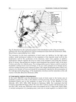
Fig. 2.36 Placement of electron beam hardening within the manufacturing sequence.
(From Zenker, R., et al. [90]. With permission.)
Electron beam heating is used within a given technological cycle. Fig.
2.36 shows the location of electron beam hardening, relative to the entire
component production cycle. Special attention should be paid to the need
© 1999 by CRC Press LLC
for demagnetization of parts prior to electron beam treatment. Non-re-
melting techniques, as a rule, do not require final finishing treatment.
Techniques in which remelting occurs, on the other hand, do usually re-
quire mechanical finishing treatment in order to give the treated surfaces
appropriate smoothness.
Electron beam treatment, both pulsed and continuous, may be applied
to parts of different surface roughness and shape and to different frag-
ments of components. The roughness of electron beam treated surfaces
should not exceed 40 µm. The shape should be such that the treated sur-
face may be held perpendicular to the electron beam. Best cases are those
of long and flat surfaces or ones with rotational symmetry (Fig. 2.37).
Fig. 2.37 Desired (a), partially desired (b) and undesired (c) shapes of parts for electron
beam heating. (From Zenker, R., et al. [90]. With permission.)
Electron beam heating of surface situated not perpendicular to the
beam is also possible, on condition that deviation does not exceed several
degrees [90, 106]. Examples of reaching different surfaces with the elec-
tron beam are shown in Fig. 2.38. Fig. 2.39 shows an example of local
hardening of a pin with a pulsed beam. In order to facilitate the harden-
ing process, manufacturers of electron beam heaters develop diagrams for
various materials, correlating the desired hardening depth with the ap-
propriate power density and heating time (Fig. 2.40).
Typical examples of electron beam hardened components are fragments of
automotive and agricultural machine parts, machine tool components (Fig.
2.41) or tools, ball bearing races, including big size, piston rings, articulated
joints, gears, crankshafts, camshafts, cams, flanges, rocker arms, rings, tur-
bine blades, saw cutting edges, cutting edges of stamping dies, milling cut-
ters turning tools, drills, etc. [18].
© 1999 by CRC Press LLC
Hardening is accomplished with electron beam heaters of several to sev-
eral tens of kilowatt power.
The advantages of electron beam treatment include the possibility of
treating surfaces which cannot be treated by conventional techniques [103,
105], cleanliness, elimination of deformations and dimensional changes,
the possibility of precise, computerized control of the electron beam [17,
103], precise control of heating parameters, possibility of treating frag-
ments of surfaces which are essentially finished and which have complex
shapes, high degree of repeatability of results, ease of automation, possi-
bility of achieving high treatment precision with tolerances of the order of
several millimeters, high productivity, low energy consumption (efficiency
reaching 80 to 90%) and, finally, the elimination of coolants.
Among disadvantages are the following: high investment cost of equip-
ment, limitation of application to selected shapes and relatively small
loads, usually not exceeding the length of several meters, the necessity of
using vacuum and to protect against X-ray radiation when the accelerating
voltage used is high - approximately 150 kV [11−14].
From the point of view of treatment quality, electron beam techniques are
comparable with laser techniques.
References
1. Szymañski, H., Friedel, K., and S ów ko, W.: Electron beam equipment (in Pol-
ish). WNT, Warsaw 1990.
2. Barwicz, W., Mulak, A., and Szymañski, H.: Application of electron optics (in
Polish). WKiL, Warsaw 1969.
3. Bielawski, M.: Application of the electron beam to metal superficial layer modi-
fication techniques (in Polish). Proceedings: Conference on The technology of for-
mation of superficial layers on metals, Rzeszów, Poland, 9-10 June 1988, pp.
126-134.
4. Barwicz, W.: More important applications of electron beams (in Polish), 1990.
Proceedings: First Polish Conference on Applications of the Electron Beam, Septem-
ber 1972, Karpacz, Poland. Transactions of The Institute for Electron Technology of
Wroclaw Technical University, No. 1, 1973, pp. 11-46.
5. Barwicz, W.: Application of electron beams in industry and research (in Polish).
OBREP, Warsaw 1974.
6. Barwicz, W.: The electron beam in industry (in Polish). WNT, Warsaw 1990.
7. Oczoœ, K.: The shaping of materials by concentrated fluxes of energy (in Polish).
Publications of the Rzeszów Technical University, Rzeszów 1988.
8. Gozdecki, T., Hering, M., and £obodziñski, W.: Electronic heating equipment (in
Polish). WSiP, Wrsaw 1979.
9. Groszkowski, J.: High vacuum technology (in Polish). PWN, Warsaw 1979.
10. Denbnoweckij, S., Felba, J., Halas, A., Melnik, W., and Lubiniec, G.: Techno-
logical electron beam guns with different types of emitters (in Polish). Proceed-
© 1999 by CRC Press LLC
ings: First Conference on Elecron Beam Techniques, Wroc a w-Karpacz, September
1982, pp. 520-531.
11. Burakowski. T.: The electron beam and possibilities of its utilization to enhance
properties of metal surfaces (in Polish). Przegl˙d Mechaniczny (Mechanical Re-
view), No. 14, 1993, pp. 14-19.
12. Burakowski, T.: The electron beam and possibilities of its utilization to enhance
properties of surfaces (in Polish). Mechanik (Mechanicien), No. 8-9, 1992, pp. 281-284.
13. Burakowski, T., Rolinski, E., and Wierzchoñ, W.: Metal surface engineering (in
Polish). Warsaw University of Technology Publications, Warsaw 1992.
14. Burakowski, T.: Formation of superficial layers - metal surface engineering (in
Polish). Metaloznawstwo, Obróbka Cieplna, In¿ynieria Powierzchni (Metallurgy, Heat
Treatment, Surface Engineering), No. 106-108, 1990, pp. 2-32.
15. Sayegh, G., and Burkett, J.: Principe et application del’emploi des faisceaux
d’electrons commande par mini-calculateurs dans le traitement thermique
superficiel des metaux. Traitement Thermique, 1979, Vol. 36, No. 136, pp. 75-89.
16. Sayegh, G.: High energy density beams (electron beam and laser beam) for heat
treatment of metals. 3rd International Congress on: Heat Treatment of Materials.
Shanghai, November 1983, pp. 8.30-8.40.
17. Modern methods of enhancement of machine component surfaces (in Russian).
Vol. 9 of series: Scientific and technical progress in machine building. Publ. In-
ternational Center for Scientific and Industrial Information - A.A. Blagonravov
Institute of the Soviet Academy of Sciences, Moscow 1989, pp. 121-133 and
157-174.
18. Sipko, A.A., Pobol, I.J., and Urban, I.G.: Strengthening of steels and alloys by
the application of electron beam heating (in Russian). Publ. Nauka i Technika,
Minsk, 1995.
19. Bielawski, M., and Friedel, K.: The electron beam as a source of heat in the
process of surface hardening (in Polish). Wiadomoœci Hutnicze (Metalmaking News),
No. 3, 1985, pp. 67-71.
20. Cahiers techniques Sciaky: Emploi des faisceaux d’electrons commandes par mini-
calculateurs dans le traitement thermique superficiel des metaux.
21. Boriskina, L.V., Kabanov, A.N., and Judaev, V.N.: About the electron beam
diffusion by material during of electron beam tratment (in Russian). Fizika i Khimia
Obrabotki Materialov (Physics and Chemistry of Material Treatment), No. 5, 1974,
pp. 78-86.
22. Ryzkov, F.N., Baskakov, A.V., and Uglov, A.A.: The amplitude of electron beam
oscillation and its effect on the shape and size of the penetration zone (in Rus-
sian). Physics and Chemistry of Material Treatment, No. 5, 1874, pp. 93-99.
23. Taniguchi, N.: Research and development of energy beam processing of materi-
als in Japan. Bulletin of Japan Society of Precision Engineering, No. 2, 1984, pp.
117-125.
24. £unarski, J., and Zielecki, W.: Modification of the condition of the technologi-
cal superficial layer and its properties by the electron beam (in Polish). Postêpy
Technologii Maszyn i Urz˙dzeñ (Progress in Machine and Equipment Technology),
Vol. 2, 1991, pp. 3-14.
25. Skubich, J., and Stöckermann, T.: Laser- und Elektronenstrahlbearbeitung in
der Fertigung. Werkstatt und Betrieb, No. 7, 1975, pp. 425-440.
26. Zielecki, W.: Modification of technological and service properties of steel by the laser
and electron beams (in Polish). Ph.D. Thesis. Rzeszów Technical University 1993.
27. Warren, P.H., and Johnson, R.H.: Selected areas of thermochemical treatment
using glow discharge electron beams. Proc.: Heat Treatment ‘84, London, May
2-4, 1984, pp. 47.1-47.6.
© 1999 by CRC Press LLC
28. Artinger, I., Korach, M., and Pachomova, N.A.: Changes in material’s structure
during surface treatment by high energy sources. Proc.: International Congress on
Heat Treatment of Materials, October 1986, Budapest, pp. 1533-1542.
29. Bakish, R.: Electron beam melting, refining and surface treatment: II. Industrial
Heating, September 1985, pp. 26-28.
30. Burakowski, T.: Directions of development in heat treatment (in Polish). Publ.:
Te chnology Section of the Machine Building Committee of the Polish Academy
of Sciences - Institute of Precision Mechanics, Warsaw 1989.
31. Burakowski, T.: Present state and directions of development of surface engi-
neering, Part IV - Characteristics and range of applications of beam techniques,
as well as possibilities of utilization of these processes in industry (in Polish).
Przegl˙d Mechaniczny (Mechanical Review), No. 16, pp. 26-35.
32. Burakowski, T.: Techniques for producing surface layers - metal surface engi-
neering. Proc.: Techniques of producing metal surface layers, Rzeszów, 9-10 June
1988, pp. 5-27.
33. Dyos, G.T., Warren, P.H., Winstanley, R., and Donnely, M.: The development
of a glow discharge electron beam heater for powder strip. Proc.: 10th Congress
of Electroheat, June 18-22, 1984, Stockholm, Sweden, paper No. 6.7.
34. Friedel, K.: Effect of the electron beam on the solid in deep penetration (in Pol-
ish). Transactions of the Institute of Electron Technology. Monograph series. Wroc a w
Te chnical University, Wroc a w 1983.
35. Friedel, K.: Thermal interaction of the electron beam with the material (in Pol-
ish). Transactions of the Institute of Electron Technology of the Wroc a w Technical
University, No. 18, Conference series No. 3, 1979, pp. 18-25.
36. Friedel, K.: The electron beam as a source of heat - physical processes (in Pol-
ish). Proc.: Implementation of electron beam welding in the machine industry, Rzeszów,
1977.
37. Rykalin, N.N., Zuev, I.V., and Uglov, A.A.: Basics of electron beam treatment of
materials (in Russian). Publ. Masinostroenye, Moscow 1978.
38. Rykalin, N.N., Uglov, A.A., Zuev, I.V., and Kokora, A.N.: Laser and electron
beam treatment of materials (in Russian). Handbook. Publ. Masinostroenye, Mos-
cow 1985.
39. Giziñski, J.: Investigation of possibility of utilization of the electron beam to
hardening heat treatment (in Polish). Report no. 109.00.0278 by Institute of Pre-
cision Mechanics, Warsaw 1989.
40. Hansen, R.C.: A comparison of high energy beam systems - electron beam/laser
beam. Proc.: The Lasers vs. the Electron Beam in Welding, Cutting and Surface
Treatment. State of the Art - 1985. Reno, part II. Edited by R. Bakish, Bakish
Materials Corp., Englewood, N.Y., 1985, pp. 255-259.
41. Hansen, R.C.: Emerging technical developments in electron beam heat treat-
ment. Proc.: Electron Beam Melting and Refining - State of Art 1984. Edited by:
R. Bakish, Bakish Materials Corp, Englewood, N.Y. 1984, p.220.
42. Barwicz, W.: Heat treatment of steel by the electron beam (in Polish). Transactions
of UNITRA OBREP, Publ. WNT, Vol. 3, No. 6, Warsaw 1975, pp. 3-11.
43. Bielawski, M., Capanidis, D., Friedel, K., and Olszewska-Mateja, B.: Appli-
cation of the electron beam to the heat treatment of contact rings in electromag-
netic clutches (in Polish). Proc.: Termoobróbka 86 (Thermal Treating 86), Jaszowiec
(Poland), May 1986.
44. Carley, L.W.: Electron beam heat treating. Heat Treating, 1977, Vol. 4, pp. 18-24.
45. Ciurapiñski, A., Waliœ, L., and Kominek, J.: An analysis of possibilities of utili-
zation of isotope techniques to study migration of elements in materials treated
© 1999 by CRC Press LLC
by PVD and low temperature CVD techniques. Part 1.2. Electron beam treat-
ment (in Polish). Internal report No. 73/I/86. Institute of Nuclear Chemistry
and Technology, Warsaw 1986.
46. Dreger, D.R.: Pinpoint hardening by electron beam. Machine Design, No. 10, pp.
89-93.
47. Ebner, R., Pfleger, E., Jeglitsch, F., Leban, K., Goldschmied, G., and Schuler,
A.: Möglichkeiten der Oberflächenbehandlung metallischer Werkstoffe mit
Elektronenstrahlen am Beispiel hochlegierter Stähle. Practical Metallography, 1988,
No. 25, pp. 467-487.
48. Fiorletta C.A.: In-line electron beam system does through surface hardening job.
Heat Treating, December 1980, Vol. 12, No. 12, pp. 28-32.
49. Gridnev, V.N., Meskov, J.J., Oskaderov, S.P., and Trefilov, V.I.: Physical prin-
ciples of electrothermal hardening of steel (in Russian). Publ. Naukova Dumka,
Kiev, 1973.
50. Gruhl, W., Grzemba, G., Ibe, G., and Hiller, W.: Durcissement superficiel par
fussion d’aliages d’aluminium avec un faisceau d’electrons. Metall, 1878, 32, No.
6, pp. 549-554.
51. Ha as, A.: Application of electron and ion beams (in Polish). Transactions of Re-
search center for Vacuum Electronics, Vol. 4, No. 9, 1976, pp. 24-26.
52. Hick, A.J.: Rapid surface treatment - a review of laser and ion beam hardening.
Heat Treatment of Metals, 1983, Vol. 10, No. 1, pp.3-11.
53. Hiller, W. , König, D., and Ibe, G.: Gezielte Beeinflussung der
Gefügeeigenschaften an der Oberfläche metallischer Werkstücke durch
Behandeln mit dem Elektronenstrahl. DVS-Berichte Strahltechnik, 1977, VIII, pp.
84-87.
54. Hiller, W., König, D., and Stolz, H.: Neue Möglichkeiten der thermischen
Behandlung von Eisenwerkstoffen mittels Elektronenstrahles. Härterei-Technische
Mitteilungen, Vol. 27, No. 2, pp. 85-91.
55. Jenkins, J.E.: Dynamic electron beam hardening cycles. Metal Progress, July 1981,
Vol.120, No. 2, pp. 38-41.
56. Jenkins, E.: Electron beam surface hardening. Tooling & Production, 1978, No.
12, pp. 76-77.
57. Keitel, S., Schultze, K.R., and Sobich, G.: Lokale Oberflächenmodifikation mit
dem Elektronenstrahl. ZIS-Mitteilungen, 1986, Vol. 28, No. 1, pp. 53-61.
58. King, R.I.: Heat treating with electron beam. Proc.: 4th ASM Heat Treating Con-
ference/Workshop, Chicago, October 1978.
59. Krasnoscenkov, M.M., Spesinskij, E.E., and Makovski, E.A.: Electron-thermal
hardening of 1045 steel (in Russian). Elektronnaya Obrabotka Metallov, 1976, No.
5, pp. 25-28.
60. Kulkinski, P.: Investigation of the effect of multiple brief austenitization on the
mechanical properties of 50CrV4 steel. Neue Hütte, 1977, Vol. 22, No. 12. pp.
669-672.
61. £unarski, J., Marsza ek, J., and Zielecki, W.: Superficial layer on 38HMJ steel
after electron treatment surface hardening (in Polish). Transactions of the Rzeszow
Technical University - Mechanics, Vol. 4, 1987, pp. 117-124.
62. £unarski, J., and Zielecki, W.: Improvement of properties of the superficial layer
by electron treatment (in Polish). Transactions of the Rzeszow Technical University
- Mechanics, Vol. 15, 1987, pp. 19-24.
63. Malajan, S.W., Venkataraman, G., and Mallik, A.K.: Grain refinement of steel
by cyclic rapid heating. Metallography, Great Britain, 1973, No. 6, pp.
337-345.
© 1999 by CRC Press LLC
64. Mawella, K.J.A., and Honeycombe, R.W.K.: Electron beam rapid quenching of
an ultrahigh strength alloy steel. Journal of Materials Science, 1984, No. 19, pp.
3760-3766.
65. Metals Handbook, Desk Editon, Part III – Processing, ch. 28- Heat Treating. ASM,
International, Materials Park, OH 44073-0002 (formerly the American Society for
Metals, Metals Park, OH 44073), Ohio, 1998, p. 28·51 (Fig. 12).
66. Mulot A., and Badeau, J.P.: Influence de la structure initiale et de la composition chimique
sur les caractéristiques des couches durcies obtenues par trempe superficielles,
bombardement électronique et laser. Traite ment Thermique, 1979, No. 136, pp. 47-63.
67. Müller, M., and Zenker, R.: Randschichthärten mit Elektronenstrahlen.
Schweisstechnik, 1986, Vol. 36, No. 11, pp. 484-486; Surface hardening by elec-
tron beam, Welding International, 1988, No. 2, pp. 180-183.
68. Rheinisch-Westfälisches Elektrizitätswerk (RWE): Die industriellen
Elektrowärmeverfahren, p. 29 - Elektronenstrahlerwärmung.
69. Leybold Heraeus borochure: Electron beam technology in vacuum metallurgy;
Electron beam special heat treatment.
70. Samoila, C., Tonescu, M.S., and Druga, L.: Technologii si utilaje moderne de
incalzire inmetalurgie (in Rumanian). Editure Technica, Bucharest 1986.
71. Sayegh, G.: Principles and applications of electron beam heat treatment. Heat
Treatment of Metals, 1980, Vol. 7, pp. 5-10.
72. Schiller, S., Hesig, U., and Panzer, S.: Elektronenstrahltechnologie. Ver lag Technik,
Berlin 1976; Elektronenstrahltechnologie, Wissenschaftliche Verlagsgeselschaft 1977;
Electron beam technology, John Wiley and Sons, New York, 1982.
73. Schiller, S., and Panzer, S.: Härten von Oberflächenbahnen mit Elektro-
nenstrahlen.Teil I: Verfahrenstechnische Grundlagen. Härterei-Technishe
Mitteilungen, 1987, Vol. 42, No. 5, pp. 293-300.
74. Schiller, S., and Panzer, S.: Härten von Oberflächen mit Elektronenstrahlen.Teil
II: Experimentelle Ergebnisse und Anwendung. Härterei-Technishe Mitteilungen,
1988, Vol. 43, No. 2, pp. 103-111.
75. Schiller, S., and Panzer, S.: Surface modifications by electron beams. Thin Solid
Films, 1984, Vol. 118, No. 1, pp. 85-92.
76. Schiller, S., and Panzer, S.: Oberflächenmodifikationen metallischer Bauteile
mit Elektronenstrahlen. Metall, 1985, No. 39, pp. 227-232.
77. Schiller, S., and Panzer, S.: Thermal surface modifications by HF-deflected elec-
tron beams. Proc.: The Lasers vs the Electron Beam in Welding, Cutting and Surface
Treatment. State of Art - 1985, Reno, NV, Part II. edited by R. Bakish, Englewood,
N.Y., Bakish Materials Corp. 1985, pp. 16-32.
78. Schiller, S., Panzer, S., and Müller, M.: Advances in the use of thermal surface
modification by electron beams. Proc.: Electron Beam Melting and Refining - State
of Art 1984, San Diego, edited by R. Bakish, Englewood, N.Y., Bakish Materials
Corp. 1984, pp. 252-261.
79. Schirmer, W., and Zenker, R.: Hochgeschwindigkeitshärten mittels Laser - und
Elektronenstrahl. Wissenschaftliche Zeitschrifts des Technische Universität Karl-
-Marx-Stadt, 1986, Vol. 23, No. 6, pp. 786-792
80. Schurath, H., Frost, H., and Panzer, S.: Oberflächenhärten mit dem
Elektronenstrahl. Kraftwerkstechnik, 1986, Vol. 26, No. 1, pp. 49-53.
81. Tosto, S., and Nenci, F.: Surface cladding and alloying of AISI 316 stainless steel
on C40 plain carbon steel by electron beam. Memoires et Etudes Scientifiques Re-
vue de Metallurgie, June 1987, pp. 311-320.
82. Stähli, G.: Die hochenergetische Kurzzeit-Oberflächenhärtung von Stahl mittels
Elektronenstrahl, Hochfrequenz- und Reibimpulsen. Härterei-Technishe
Mitteilungen, 1974, Vol. 29, No. 2 pp. 55-67.
© 1999 by CRC Press LLC
83. Zenker, R.: Stand, Ergebnisse und Entwicklungsrichtungen auf dem Gebiet der
Elektronenstrahl - Randschichtveredelung. Proc.: 3 Wärmebehandlungstagung -
Grundlagen und Anwendung moderner Wärmebehandlungstechnologien für
Eisenwerkstoffe, 31 May- 22 June 1988, Karl-Marx-Stadt, Technische Universität
Karl-Marx-Stadt, pp. 93-103.
84. Stähli, G.: Traitement thermique rapide. Traitement Thermique, 1986. No. 199,
pp. 43-52; Kurzeit-Wärmebehandlung, Härterei-Technishe Mitteilungen, 1984, Vol.
39, No. 3, pp.81-89.
85. Steigerwald, K.H., and Hiller, W.: Thermal and structural effects of electron
beam heating and welding processes on metals. Proc.: 18th International Confer-
ence on Heat Treatment of Materials, Detroit, May 1980, pp. 363-373.
86. Zenker, R.: Elektronenstrahl - Randschichtwärmebehandlung - Technologische
Möglichkeiten und Anwndungsprinzipien. Proc.: 12 Fachtagung Wärmebe-
handlungs und Werkstofftechnik, 12-14 Dec, 1988, Gera, Kammer der Technik, pp.
68-81.
87. Zenker, R., John, W., Kämpfe, B., Rathjen, D., and Fritsche, G.: Gefüge- und
Eigenschaftänderungen ausgewählter Stähle beim Elektronenstahlhärten.
Wissenschaftsliche Zeitschrifts des Technischen Universität Karl-Marx Stadt, 1988,
30, No. 2, pp. 165-182.
88. Zenker, R., and Müller, M.: Electron beam hardening, part I - Principles, pro-
cess technology and prospects. Heat Treatment of Metals, No. 4, 1988, pp. 79-88.
89. Zenker, R., and Müller, M.: Randschichthärten mit Elektronenstrahlen -
verfahrenstechnische Möglichkeiten und werstofftechnische Effekte. Neue Hütte,
1987, Vol. 32, No. 4, pp. 127-134.
90. Zenker, R., Müller, M., and Furchheim, B.: Wärmebehandlungstechnologische
und verfahrenstechnishe Aspekte und Anwendungsbeispiele des
Elektronenstrahlhärtens. Proc.: Tagungsband: 11 Fachtagung Wärmebehandlungs-
und Wertkstofftechnik, Gera 1986. Kammer der Technik, Vortrag No. 13, pp. 98-114.
91. Zenker, R., and Panzer, S.: Stand, Ergebnisse und Perspektiven des
Elektronenstrahl-Randschichthärtens. Freiberger Forschungshefte, Reihe B,
Bergakademie Freiberg, 1987, pp. 13-26.
92. Zenker, R., and Schirmer, W.: Zum Einfluss des Hochgeschwindigkeitshärtens
auf Struktur, Gefüge und Eigenschaften ausgewählter Stähle. Proc.: 5th Interna-
tional Congress on Heat Treatment of Materials, October 1986, Budapest.
93. Zenker, R.: Electron beam surface modification - results and perspectives. Proc.:
7th International Congress on Heat Treatment of Materials. Moscow, 11-14 Dec.,
1990, pp. 281-289.
94. Zenker, R.: Gefüge- und Eigenschaftsgradienten beim Elektronenstrahlhärten.
Härterei-Technische Mitteilungen, No. 5, 1990, pp.307-319.
95. Pobol, I.L.: Worldwide tendencies in applications of high energy electron beams
to metal treatment (in Polish). Elektronika (Electronics), 1993, Vol. 34, No. 8-9, pp.
41-47.
96. Hiller, W.: Traitement de surface par refusion des materiaux metalliques l’aide
d’un faisceau d’electron. Batelle Information, 1986, No. 3, pp. 22-23.
97. Kear, B.H., and Strutt, P.R.: Rapid solidification of surface modification of mate-
rials. Proc.: Electron Beam Melting and Refining - State of Art 1984, San Diego.
Edited by R. Bakish, Englewood, N.Y., Bakish Materials Corp., 1984, p. 234.
98. Friedel, K.: Electron beam technology in industrial applications (in Polish).
Elektronika, No. 7-9, 1990, pp.25-27.
99. Stutt, P.P.: Formation of rapidly melted surface layers by electron beam scan-
ning. Materials Science Engineering, 1981, No. 49, pp. 87-91.
© 1999 by CRC Press LLC
100. Nestler, M.C., Spies, H.J., Panzer, S., and Müller, H.: Erzeugung von
Verschleissshutzschichten durch Randschichtumschmeltzlegierungen mit
energiereicher Strahlung. Proc.: Härtereitechnische Fachtagung Härtereitechnik
1989, Kammer der Technik, Suhl, 8-10 Nov. 1989, pp. 113-119.
101. £unarski, J., and Zielecki, W.: Investigations of possibility of molybdenum alloy-
ing of steel by the electron beam (in Polish). Postêpy Technologii Maszyn
i Urz˙dzeñ (Progress in Machine and Equipment Technology), Vol. 2, 1992, pp. 3-17.
102. Zielecki, W., and Sêp, J.: Electrochemical properties of 38HMJ steel, molybde-
num alloyed by the electron beam (in Polish). Transaction of Rzeszów Technical
University - Mechanics, Vol. 34, 1992, pp. 77-82.
103. Gilbert, G.L.: Computerized control of electron beam for precise surface hard-
ening. Industrial Heating, 1978, Vol. 45, No. 1, pp. 16-18.
104. Dietrich, W., Stephan, H., and Fischoff, J.: Application of electron beam tech-
nology in the metallurgical industries. Bulletin d’Information U.I.E., Dec. 1978,
No. 27, pp.4-7.
105. Demidov, B.A., Kriznik, G.S., and Tomaschik, J.F.: Changes in metal structure
after introduction of intensive fluxes of electrons of nanosecond frequency (in
Russian). Fizika i Chimia Obrabotki Materialov, 1982, No. 4, pp. 114-117.
106. Zenker, R.: Electron beam surface modification - state of art. Materials Science
Forum, 1992, No. 102-104, pp. 459-476.
107. Zenker, R.: Materials aspects of surface modification by electron beams and indus-
trial applications today. Surface Treatment - Solid State, ECLAT-90, pp. 237-249.
108. Spies, H.J., Zenker, R., and Nestler M.C.: Electron beam treatment of surface
layer. Journal of Advanced Science, 1993, Vol. 5, No. 2, pp. 50-60.
109. Bielawski, M.: Modification of surface of metals by the electron beam (in Pol-
ish). Elektronika (Electronics), 1993, Vol. 34, No. 8-9, pp. 48-50.
110. Frey, H., and Kienel, G.: Dünschicht Technologie. VDI Verlag, Düsseldorf 1987.
© 1999 by CRC Press LLC
chapter three
The solid surface
3.1 The significance of the surface
The surface of living organisms limits them and protects them from the
environment. Similarly, in technology, the surface limits structural mate-
rials, separates them from the surrounding medium or the environment,
but, at the same time, establishes contact with surrounding medium. In
surface engineering, the fundamental object of research, design, enhance-
ment (during the manufacturing process) and, finally, of wear (during
service) is the solid surface.
The solid surface - of a tool, of a part of a machine, of an element or
even of a finished product - has for many years been the object of physi-
cal and chemical processes which impart to it required service properties,
better than those of the core (or substrate). When the usable properties of
the objects are related to its chemical resistance, wear resistance, partially
to fatigue strength, thermal or electrical conduction, proper modification of
the surface of cheaper and less resistant materials can successfully replace
the use of those materials which feature in their entire volume the right prop-
erties, such as anti-corrosive, anti-wear or decorative, typical of costly materi-
als (e.g., gold), or difficult to machine (e.g., austenitic stainless steels, sintered
carbides).
According to A. A. Griffith, as quoted by L. Szulc [1], the image of the
real structure of a solid, including metals, which is of special interest to us is
“a set of interruptions of macro and microscopic continuity, consisting of
crevices, porosity and irregularities in structure, laminar or mosaic in charac-
ter, or caused by the inclusion of foreign matter.” If we further accept his
premise that faults and irregularities of structure originate at the surface or
occur chiefly in its direct vicinity, it is difficult to underestimate the signifi-
cance of the surface in the process of technological shaping of properties and
their utilization during service.
The surface of a solid is usually characterized by a structure and prop-
erties which differ from that of the core of the material. This difference
stems predominantly from the following:
–a distinct energy condition, causing a state of elevated energy and
enhanced adsorption activity [2],
– combination of mechanical, thermal, electrical, physical and chemi-
cal effects at the surface during processing of the object,
– cyclic or continuous: mechanical, thermal, chemical or physical ac-
tion of the environment of the object on its surface during service.
© 1999 by CRC Press LLC
The surface exerts a fundamental influence on the usable properties of
objects and solids. Several physico-chemical effects, such as chemical cataly-
sis, corrosion, wear (abrasive, adhesive, combined abrasive-adhesive, ero-
sion, clotting, cavitation, fatigue, oxidation or flaking), adhesion, adsorption
(physical and chemical), flotation, diffusion and passivation all depend on
and occur at the material surface or with its participation [3].
The surface of a solid constitutes a specific research, technological and
design problem.
The concept of the surface is perceptible and understandable by intu-
ition; it is, however, quite difficult to define and understand in a precise
manner. Usually, the definition of surface is not clear-cut. In fact, this
concept has been defined in a number of ways, depending on the discipline
of science or technology for the purpose of which it is used.
3.2 The surface - geometrical concept
In the mathematical sense, and more strictly, geometrical, the surface is a
two-dimensional geometrical figure, e.g., a sphere or a cylinder, and constitutes
one of the basic concepts of geometry. In elementary geometry, surfaces are
described as certain sets of points or straight lines with certain properties, i.e., loci
of points with a given characteristic.
It is evident from such definitions that the mathematical concept of
the surface is purely theoretical and not material.
3.3 The surface - mechanical concept
Closer to reality is the concept of the surface used in applied mechanics
and related technical sciences.
The surface is defined here as the edge (or limit) of material bodies.
This is a very general concept, dependent on the scale of the effect consid-
ered - molecular, micro and macro.
The material surface is defined as a continuous material system in the
form of a surface, comprising material points.
Finer differentiation in the description of surface concepts is attributed
to a team of Polish scientists, under the leadership of Prof. Jan Kaczmarek,
who in the 1950s laid down some scientific foundations for such processes
as machining, abrasion and erosion [4]. Since the first of these has been the
oldest and the most widely used of processes forming the geometry of objects
- it was in this field that the most significant first achievements were accom-
plished. These are contained in many published documents, of which of
greatest significance was the Polish Standard PN-73/M-04250 [5], and they
formulate the following new definitions:
Nominal surface - the surface as described by a blueprint or technical
documentation, with the omission of roughness, waviness and shape errors.
This, of course, is the theoretical surface; earlier called the geometrical
surface.
© 1999 by CRC Press LLC
Fig. 3.1 Images of observed surfaces: a) chromium-aluminium coating on austenitic
300 series steel, 300 ϫ; b) Discalloy sintered P/M, 1000 ϫ; c) phosphate coating with
gold vapor deposit, 2000 ϫ; d) surface of oxynitride layer, obtained by the ONC method,
1000 ϫ.
True or real surface - the surface limiting the object (its solid shape),
separating it from the environment. The concept of the real surface, correct
in the general sense, depends, however, on the scale of the phenomena con-
sidered. For the “macro” scale the concept is adequate to the definition. But
for the “micro” scale, especially down to the scale of the atom, where there is
b)
© 1999 by CRC Press LLC
a necessity to take into account the subtle interaction of the environment
with the object, this concept is more difficult to be precisely understood.
The concept of the observed surface substantially facilitates this under-
standing.
The observed (measured) surface - an approximated image of the real
surface of an object, obtained as a result of observation (e.g. with the aid of a
scanning electron microscope) or measured within the bounds if precision
achievable by observation or measurement (by a given method of measure-
ment) (Fig. 3.1).
The above concepts may be supplemented by general descriptions con-
nected with the processing of the object, proper not only for machining
but for all types of processing.
The surface being processed - the surface which constitutes the bound-
ary of the processed object in the area subjected to processing.
The processed surface - the surface which constitutes the boundary of the
processed object in the area where the processing was carried out.
3.4 The surface - physico-chemical concept
3.4.1 The phase
The phase is a homogenous part of a system with same physical properties in its
entire mass and with same chemical composition, separated by an interface sur-
face (phase boundary from another part [phase] of that system). For example, a
gas or a gas mixture constitutes one phase, similarly to a homogenous
liquid or a solution. On the other hand, a mixture of two non-mixing
constituents, as e.g., oil and water, constitutes two inhomogenous phases.
The system, ice - water - water vapour, is a homogenous tri-phase system.
The phases of the system may be separated from one another by mechani-
cal means, e.g., by decanting, filtration, centrifuging, sifting.
Constituents of the system are all those substances from which the sys-
tems are built. Further, an independent constituent is such that its type and
quantity, if known, are sufficient to determine the chemical composition of
each phase of the system. A phase or a system, composed of only one inde-
pendent constituent is called homogenous, and one that is composed of many
such constituents, is termed a heterogeneous system. Thus, there may exist
the following [6]:
–monophase and one-constituent system (e.g., pure water), or uniform
and homogenous system,
–monophase and multi-constituent system (e.g., solution of sugar in
water) or uniform and heterogeneous system,
–multi-phase and one-constituent system (e.g., ice and water) or non-
uniform and homogenous system,
– multi-phase and multi-constituent system (e.g., solution of alcohol in
water and their vapor) or non-uniform and heterogeneous system.
© 1999 by CRC Press LLC
A transition within the considered system from one crystallographic form
to another (e.g.,
α
-iron to
γ
-iron) or the creation of a new chemical bond (e.g.,
of an intermetallic compound during solidification of a metal alloy) is al-
ways accompanied by the creation of a new phase.
In all dispersed systems (e.g., in emulsions) one of the phases is made up
of the entire mass of the dispersing medium (e.g., water), while the second
phase is the entire mass (all droplets) of the dispersed substance (e.g., oil).
A homogenous metal alloy constitutes only one phase; although it con-
tains many grains of varying shapes and sizes, which can be separated
from one another, all grains have the same chemical composition, there-
fore they constitute only a portion of the system. In the case of melting a
metal alloy the system initially comprises two phases: the liquid and the
solid crystals within it. These crystals can be separated mechanically from
the liquid (e.g., with the use of a sieve). A fully melted alloy does not, as a
rule, contain any additions which could be separated out of it by me-
chanical means. It has the same chemical composition throughout its mass,
is homogenous and comprises one phase only. This stems from the ability
of the majority of metals to dissolve in one another in the liquid phase in
any given proportions. The only exception is the alloy of lead and iron [7].
A non-homogenous metal alloy is multi-phased. The particular alloy
phases usually differ quite significantly in properties, and their number,
type, as well as properties depend on the chemical composition of the
alloy.
3.4.2 Interphase surface - a physical surface
The dividing surface between phases (phase boundary) constitutes and
interface, termed also inter-phase boundary or boundary surface (in fluid
mechanics); in the case of the liquid-gas system the interface is termed
level (as in water level).
The concept of interface was first introduced in 1878 by J. W. Gibbs
who considered the simplest theoretical mono-constituent, biphase sys-
tem. In this system one can distinguish three areas (Fig. 3.2): a homoge-
neous zone of phase A, a homogenous zone of phase B and a heteroge-
neous interface zone C. Zone C does not constitute a third phase in the
strict sense of the phase rule. It can be treated as a fictitious individual
portion of the system which is in equilibrium with the extraneous interac-
tions between the phases A and B, i.e. temperature, pressure, chemical
potentials, concentration, specific mass, etc. Gibbs treated the interface as
a physical inter-phase surface. He, moreover, proposed the concept of a
mathematical two-dimensional boundary surface, characterized by a di-
rected force of surface tension, connected with pressure. Such a surface
embodies the physical interface. This zone is characterized by an aniso-
tropy of pressure, connected with the heterogeneity of the interface zone across
its thickness.
© 1999 by CRC Press LLC
Fig. 3.3 Pattern representation of “hanging bonds” of a surface with atomic (cova-
lent) bonds. (From Hebda, M., and Wachal, A.[8]. With permission.)
water at the interface with a solid occurs in a different from normal allo-
tropic form which does not expand upon solidification);
2) equalization by the interface of the differences between the adjoin-
ing; the heterogeneity of the interface is expressed by the occurrence of
internal electrical and mechanical fields causing a compensation of the
gradients of chemical potential in the direction of maintaining a constant
value of the electrochemical potential in the entire system (which consti-
tutes a condition of thermodynamic equilibrium).
The clarification of the above statements facilitates an atomistic de-
scription of the simplified system, in the form of an ideal (i.e., no defect struc-
ture) solid crystal (e.g., of a metal), situated within ideal vacuum. The inside
of that crystal can be identified with that of a system of atom structures,
surrounded by potential fields of their interactions. The distribution of these
fields determines the situation of valence electrons which are responsible for
chemical bonds between atoms. Such bonds are, of course, mutually compen-
sated within the crystal but there is no compensation on the crystal surface.
The surface layer of atoms has unsaturated chemical bonds in the direction
perpendicular to it and these may be termed “hanging bonds” (Fig. 3.3) [8].
The potential energy of valence electrons of surface atoms, therefore of sur-
face atoms themselves, is different from that of atoms from within the crystal.
The described surface is not an inter-phase surface because while the
solid constitutes a phase, ideal vacuum cannot be termed a phase. (Tech-
nical vacuum may be a phase - the lower the degree of vacuum, the more
its properties approach those of a real phase). The said surface, however,
does constitute a boundary surface which may, in the general sense, be
identified with a real surface.
Boundary surfaces exist only when component elements of the solid -
its atoms, ions or molecules - are mutually bonded by strong forces of
adhesion. If these forces are small, the dissolution of one substance in the
other takes place [8].
© 1999 by CRC Press LLC
The described surface is, from an atomic standpoint, pure, not contami-
nated by atoms from a material environment of the solid. Since it has unsat-
urated chemical bonds, it is highly active, both chemically and physically.
Such a surface behaves as though it is waiting for the possibility of attaching
atoms, ions and molecules from the material environment.
If the solid is placed in a gas or a liquid, the boundary surface becomes an
inter-phase surface, or simply, an interface. Similarly as in the case of a
vacuum, the molecules of the solid making up the surface are in conditions
different from those of same elements but situated inside the solid. From the
external side of the interface the molecules of the solid are in contact with
molecules of a foreign phase, interacting with them with forces different
from those of elements of the same phase (Fig. 3.4). For liquids and gases,
such forces are substantially weaker than those acting from the side of their
own phase. As a result, the molecules of the solid have a portion of the forces
not compensated and the surface is richer in energy than the inside of the solid
[8]. Naturally, the molecules of the solid are subjected to interaction from
molecules directly adjoining them (strongest forces), as well as from those
situated deeper. The further away from the surface, the weaker the interac-
tion with molecules at the surface (Fig. 3.5) [8].
Fig. 3.4 Representation of forces acting on particles situated inside the solid and at its
surface. (From Hebda, M., and Wachal, A. [8]. With permission.)
Fig. 3.5 Share of energy by atoms of the subsurface layer in the total energy of the
surface. (From Hebda, M., and Wachal, A. [8]. With permission.)
© 1999 by CRC Press LLC
Fig. 3.6 Schematic representation of field of forces on surface of different shapes:
a) plane surface; b) edge; c) corner. (From Hebda, M., and Wachal, A. [8]. With permis-
sion.)
Atoms at the surfaces of solids have a very limited freedom of move-
ment. Saturation of forces of adhesion between them depends on other
atoms in their vicinity. The smaller their number in direct proximity of a
given atom, the lower the degree of saturation of adhesion forces and
hence, the higher the surface energy (Fig. 3.6) [8].
Grain edges of crystals are richer in energy than a flat surface which
manifests itself by the greater reactivity of atoms situated at grain bound-
aries, leading to e.g., the development of intergranular corrosion. More active,
both chemically and physically, is a rough surface, in comparison with a
smooth one. Similar effects are caused by structural defects, residual stresses,
microcracks, porosity, scratches and crevices.
A measure of undersaturation of adhesion forces between molecules of
a solid - both inside and on the surface - is surface energy. It is an insepa-
rable property of the surface and its magnitude and distribution depend
on the type of chemical bonds, i.e., on the type of the body. It is mainly a
property of solids, regardless of the degree of structural ordering.
Surface energy is the difference between the total energy of all atoms
or surface molecules and the energy which they would have if they were
situated inside the solid. A measure of surface energy is the work which
must be carried out to displace atoms from inside the solid to its surface.
1) The critical state - a state of a biphase (one component) system in which the physical proper-
ties of both phases existing in equilibrium are identical.
Surface energy in the critical condition1 (i.e., at critical temperature and
© 1999 by CRC Press LLC