Mechanics of Materials 1 Part 12 docx
Bạn đang xem bản rút gọn của tài liệu. Xem và tải ngay bản đầy đủ của tài liệu tại đây (2.92 MB, 70 trang )
272 Mechanics of Materials
2
98.27
8.27.4.
Forms
of
stress function in polar coordinates
In cylindrical polars the stress function is, in general, of the form:
=
f
(r)cosnO or
4
=
f(r)sinne (8.104)
where
f
(r) is a function of r alone and n is an integer.
expression used for the Cartesian coordinates, by considering the following three cases:
(a) The axi-symmetric case when n
=
0
(independent of
e),
4
=
f
(I). Here the biharmonic
In exploring the form of
4
in polars one can avoid the somewhat tedious polynomial
eqn. (8.102) reduces to:
2
($+;;)
4=0
and the stresses in eqn. (8.103) to:
-c#
=
0
d24
,
a&?=-
a,,
=
r dr dr2
'
1
d4
Equation (8.105) has a general solution:
q5
=
Ar2
In r
+
Br2
+
Clnr
+
D
(b) The asymmetric case n
=
1
4
=
f
l(r)sinO or
4
=
f
l(r)cosO.
Equation (8.102) has the solution for
f
l(r)
=
Air3 +Bl/r
+
Clr +Dlrlnr
i.e.
(c) The asymmetric cases n
3
2.
4
=
(Alr3
+
Bl/r
+
Clr +Dlrlnr)sinO
(or cos@
(8.105)
(8.106)
(8.107)
(8.108)
4
=
f,(r)sinnO or
4
=
fn(r)cosnO
fn(r)
=
A,r"
+
B,r-"
+
Cnrflf2
+
D,,r-n+2
(8.109)
i.e.
4
=
(A,r"
+
B,r-"
+
C,rn+2
+
D,r-n+2)sinnt9 (orcosne)
Other useful solutions are
4
=
Cr sin6 or
4
=
CrcosO (8.110)
In the above
A,
B,
C
and
D
are constants of integration which enable formulation of the
various problems.
As
in the case of the Cartesian coordinate system these stress functions must satisfy the
compatibility relation embodied in the biharmonic equation (8.102). Although the reader is
assured that they are satisfactory functions, checking them is always a beneficial exercise.
In those cases when it is not possible to adequately represent the form of the applied
loading by a single term, say cos28, then a Fourier series representation using eqn. (8.109)
can be used. Details of this are given by Timoshenko and G0odier.t
t
S. Timoshenko and
J.N.
Goodier,
Theory
ofElasricify,
McGraw-Hill, 1951.
$8.27 Introduction to Advanced Elasticity Theory 273
In the presentation that follows examples of these cases are given. It will be appreciated
that the scope of these
are
by no means exhaustive but a number of worthwhile solutions are
given to problems that would otherwise be intractable. Only the stress values are presented
for these cases, although the derivation of the displacements is a natural extension.
8.27.5. Case 2
-
Axi-symmetric case: solid shaji and thick cylinder radially loaded with
uniform pressure
This obvious case will be briefly discussed since the
Lam6
equations which govern this
Substituting eqn. (8.107) into the stress equations (8.106) results in
problem are
so
well known and do provide a familiar starting point.
=
A(l
+
21nr)
+
2B
+
C/r2
am
=
A(3
+
2
In
r)
+
2B
-
C/r2
Td
=
0
J
(8.111)
When a solid shaft is loaded on the external surface, the constants
A
and
C
must vanish to
avoid the singularity condition at
r
=
0.
Hence
arr
=
am
=
2B. That is uniform tension, or
compression over the cross section.
In the case of the thick cylinder, three constants, A, B, and
C
have to be determined. The
constant
A
is found by examining the form of the tangential displacement
w
in the cylinder.
The expression for this turns out to be a multi-valued expression in
8,
thus predicting a
different displacement every time
8
is increased to
8
+
2rr.
That is every time we scan one
complete revolution and arrive at the same point again we get a different value for
v.
To
avoid this difficulty we put
A
=
0.
Equations (8.1 11) are thus identical in form to the Lam6
eqns. (10.3 and
10.4).?
The two unknown constants are determined from the applied load
conditions at the surface.
8.27.6. Case
3
-
The pure bending of
a
rectangular section curved beam
Consider a circular arc curved beam
of
narrow rectangular cross-section and unit width,
bent in the plane of curvature by end couples
M (Fig. 8.33). The beam has a constant cross-
section and the bending moment is constant along the beam. In view of this one would
expect that the stress distribution will be the same on each radial cross-section, that is, it
will be independent of
8.
The axi-symmetric form of
@,
as given in eqn. (8.107), can thus
be used:-
i.e.
@
=
Ar2
lnr
+
Br2
+
Clnr
+
D
The corresponding stress values are those of eqns (8.1 11)
a,,
=A(1 +21nr)+2B+C/r2
am
=
A(3
+
2
In
r)
+
2B
-
C/r2
rd
=
0
t
E.J. Hem,
Mechanics
of
Muteriols
I,
Butterworth-Heinemann,
1997.
274
Mechanics
of
Materials
2
58.27
Fig.
8.33.
Pure bending
of
a curved beam
The boundary conditions for the curved beam case are:
(i)
a,,
=
0
at
r
=
a
and
r
=
b
(a
and
b
are the inside and outside radii, respectively);
(ii)
s,
a@
=
0,
for
the
equilibrium of forces, over any cross-section;
(iii)
s,
ow
rdr
=
-M,
for the equilibrium of moments, over any cross-section;
(iv)
rd
=
0,
at the boundary
r
=
a
and
r
=
6.
b
b
Using these conditions the constants
A,
B
and
C
can be determined. The final stress
equations are as follows:
r
1
r
a,,
=
-
-
-
a2
In
-
-
b2
In
-
U
r
a2b2 b
r
Q
a
In
-
-
a2
In
-
-
b2
In
(8.112)
rfi
=
0
J
where
Q
=
4a2b2
In
-
-
(b2
-
a2)*
The distributions of these stresses are shown on Fig.
8.33.
Of
particular note is the
nonlinear distribution of the
am
stress. This predicts a higher inner fibre stress than the
simple bending
(a
=
My/[)
theory.
(
:)2
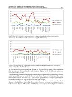
8.27.7.
Cau
4.
Asymmetric case
n
=
1.
Shear loading
of
a
circular arc cantilever beam
To illustrate this form of stress function the curved beam is again selected; however, in
this case the loading is a shear loading as shown in Fig.
8.34.
As
previously the beam
is
of narrow rectangular cross-section and unit width. Under
the
shear loading
P
the bending moment at any cross-section is proportional to sin8 and,
therefore it is reasonable to assume that
the
circumferential stress
would also be associated
with sin8. This points to the case
n
=
1
and a stress function given in eqn.
(8.108).
i
.e.
$=
(A~r~+B~/r+C~r+D~rInr)sinB
(8.
I
13)
Using eqns.
(8.103)
the three stresses can be written
3
8.27
arr
=
-
P
(r+
-
sine
'
S
r r
a@
=
-
(i ri
a2b2
a'
+
b')
r*
=
r+
S
r
P
(
a::'
a'
+b2)
COS
e
S
r
I
Introduction to Advanced Elasticity Theory
275
-
!'EloS+ici+y' opprooch
Simple
bending
Qee
For
8.L
2
Fig.
8.34.
Shear loading
of
a
curved cantilever.
a,,
=
(2Alr
-
2Bl/r3
+
Dl/r)sinO
am
=
(6A1r+2B1/r~+Dl/r)sinQ
rrc,
=
-(2Alr
-
2Bl/r3
+D~/r)cosO
(8.1
14)
The boundary conditions are:
(i)
a,,
=
rd
=
0,
for
r
=
a
and
r
=
6.
(ii)
sob
rd
dr
=
P,
for
equilibrium of vertical forces at 8
=
0.
(8.115)
where
s
=
a2
-
b2
+
(a2
+
6')
In
b/a.
It is noted from these equations that at the load point 6
=
0,
or,
=
am
=
0
rd= (r+T
P
a2b2
a2
+b2)}
S
r r
(8.1
16)
276 Mechanics
of
Materials
2
$8.27
As in the previous cases the load
P
must be applied to the cantilever according to
eqn.
(8.1
16)
-
see Fig.
8.34.
n
2
S
r
P
(
a::2
a2
+b2)
1
r
+
-
-
___
At the fixed end, 8
=
-;
a,,
=
-
a2b2
a2
+
b2
r
(8.117)
Td
=
0
The distributions
of
these stresses are shown in Fig.
8.34.
They are similar to that for the pure
moment application. The simple bending
(a
=
My/Z)
result is also shown.
As
in the previous
case it is noted that the simple approach underestimates the stresses on the inner fibre.
8.27.8.
Case 5-The asymmetric cases n
3
2-stress concentration at a circular hole in a
tension field
The example chosen to illustrate this category concerns the derivation
of
the stress concen-
tration due to the presence
of
a
circular hole in a tension field. A large number
of
stress
concentrations arise because
of
geometric discontinuities-such as holes, notches, fillets, etc.,
and the derivation
of
the peak stress values, in these cases, is clearly
of
importance to the
stress analyst and the designer.
The distribution
of
stress round a small circular hole in a flat plate
of
unit thickness subject
to a uniform tension
a,,
in the
x
direction was first obtained by Prof. G. Kirsch in
1898.t
The width
of
the plate is considered large compared with the diameter
of
the hole as shown
in Fig.
8.35.
Using the Saint-Venant'sf principle the small central hole will not affect the
Fig.
8.35.
lo
I
I
\
\
I
/
/
-
\
/
\
/
'\
\
Elements in
a
stress field some distance from
a
circular hole.
G.
Kirsch
Verein Deutsher Ingenieure (V.D.I.)
Zeifschrif,
42
(1898),
797-807.
B.
de Saint-Venant,
Mem.
Acud.
Sr.
Savants
E'frungers,
14
(1855).
233-250.
58.27
Introduction
to
Advanced Elasticity Theory
277
stress distribution at distances which
are
large compared with the diameter
of
the hole-say
the width
of
the plate. Thus on a circle of large radius
R
the stress in the
x
direction, on
8
=
0
will be
a,.
Beyond the circle one can expect that the stresses are effectively the same
as in the plate without the hole.
Thus at an angle
8,
equilibrium of the element ABC, at radius
r
=
R,
will give
a,.,.AC
=
a,BCcos8, and since, cos8
=
BC/AC
or,
=
O,COS~~,
*,
2
TH.
AC
=
-o,BC sin
8
or
or,
1
-(1
fc0~28).
Similarly,
ffn
2
:.
~d
=
-crxx
cos
8
sin
8
=
-
-
sin 28.
Note the sign
of
~d
indicates a direction opposite to that shown on Fig.
8.35.
Kirsch noted that the total stress distribution at
r
=
R
can be considered in two parts:
(a) a constant radial stress an/2
(b) a condition varying with
28,
that is;
or,
=
-
cos
26,
T~
=
-
-
sin 28.
ff,
ff,
2 2
The final result is obtained by combining the distributions from (a) and (b).
Part (a), shown
in
Fig.
8.36,
can be treated using the Lam6 equations; The boundary conditions are:
at
r =a
or,
=
0
Using these in the Lam6 equation,
a,,
=
A
+
B/r2
gives,
A=!?(L)
and B=-%( )
R2a2
2
R2
-
a2
2
R2 -az
Fig.
8.36.
A
circular plate loaded at the periphery with
a
uniform
tension.
278 Mechanics
of
Materials
2
$8.27
a,
a=
2
When
R
>>
a
these can be modified to
A
=
-
and
B
=
a
2 2
(8.1 18)
1
a,,
=
a-
(1
-
$)
am
=
a-
(1
+
;)
Thus
2
2
rd
=
0
Part
(b),
shown
in
Fig
8.37
is a new case with normal stresses varying with cos
28
and shear
stresses with sin
28.
Fig.
8.37.
A
circular plate loaded at the periphery with a radial stress
=
2
cos20
(shown above) and a shear
stress
=
-
-
sin
28.
2
0,
2
This fits into the category of
n
=
2
with a stress function eqn.
(8.109);
i.e.
Using eqns.
(8.103)
the stresses can be written:
4
=
(A2r2
+
Bz/r2
+
C2r4
+
D2)cos
28
(8.119)
(8.120)
1
a,,
=
-(2A2
+
6B2/r4
+
4D2/r2)
cos
28
OM
=
(2A2
+
6B2/r4
+
12C2r2)cos28
rd
=
(2A2
-
6B2/r4
+
6C2r2
-
2D2/r2)
sin
28
The four constants are found such that
a,,
and
r,+
satisfy the boundary conditions:
at
r
=
a,
at
r
=
R
-+
co,
a,,
=
rd
=
0
am
0,
2 2
or,
=
-
cos28,
rd
=
sin28
From these,
A2
=
-a,/4,
B2
=
a,a4/4
C2
=
0,
02
=
axxa2/2
98.27
Thus:
Zntroduction to Advanced Elasticity Theory
am
=
-0-
2
(1
+
Z)
cos26
279
(8.121)
a,
2
T,+
=
(
1
+
2a2/r2
-
3a4/r4) sin26
The sum of the stresses given by eqns. (8.120) and (8.121) is that proposed by Kirsch. At
the edge of the hole
a,,
and
T,+
should be zero and this can be verified by substituting
r
=
a
into these equations.
The distribution of
am round the hole, i.e.
r
=
a, is obtained by combining eqns. (8.120)
and (8.121):
i.e.
am
=
a,(i
-
2cOsm) (8.122)
and is shown on Fig. 8.38(a).
When
6
=
0;
am
=
-axx
and when
6
=
-;
am
=
30,.
The stress concentration factor
(S.C.F)
defined
as
Peak stresslAverage stress, gives an
S.C.F.
=
3
for this case.
?r
2
The distribution across the plate from point
A
am=-
a,,
(
2+-+-
;;
3;4)
2
(8.123)
This is shown in Fig. 8.38(b), which indicates the rapid way in which
am
approaches
a,
as
r
increases. Although the solution
is
based on the fact that
R
>>
a, it can be shown that
even when
R
=
4a, that is the width
of
the plate is four times the diameter of the hole, the
error in the S.C.F. is less than
6%.
Using the stress distribution derived for this case it is possible, using superposition, to
obtain S.C.F. values for a range
of
other stress fields where the circular hole is present, see
problem No. 8.52 for solution at the end of this chapter.
A similar, though more complicated, analysis can be carried out
for
an elliptical hole of
major diameter 2a across the plate and minor diameter 26 in the stress direction. In this
case the S.C.F.
=
1
+
2a/b (see also 98.3). Note that
for
the circular hole
a
=
6, and the
S.C.F.
=
3,
as above.
8.27.9.
Other useful solutions of the hiharmonic equation
(a)
Concentrated
line
load
across
a
plate
The way in which an elastic medium responds to a concentrated line
of
force is
the
final illustrative example to
be
presented in this section. In practice it is neither possible to
apply a genuine line load nor possible for the plate
to
sustain a load without local plastic
deformation. However, despite these local perturbations in the immediate region
of
the load,
the rest
of
the plate behaves in an elastic manner which can be adequately represented by
the governing equations obtained earlier. It is thus possible to use the techniques developed
above to analyse the concentrated load problem.
280
Mechanics
of
Materials
2
$8.27
c
I
W
t-
Fig. 8.38. (a) Distribution of circumferential stress
am
round the hole in a tension field; (b) distribution of
circumferential stress
CT~
across
the
plate.
IP
tv
Fig. 8.39. Concentrated load on a semi-infinite plate.
Consider a force
P
per unit width
of the plate applied
as
a line load normal to the
surface
-
see Fig.
8.39.
The plate will be considered as equivalent
to
a semi-infinite solid,
that is, one that extends to infinity in the
x
and
y
directions below the horizon,
8
=
&:;
The
plate is assumed
to
be of unit width. It is convenient to use cylindrical polars again for this
problem.
$8.27
Introduction
to
Advanced Elasticity Theory
28
1
Using Boussinesq's solutions? for a semi-infinite body, Alfred-Aim6 Flamant obtained (in
1892)zthe stress distribution for the present case. He showed that on any semi-circumference
round the load point the stress is entirely radial, that is:
a@
=
t,s
=
0
and
a,,
will be
a principal stress. He used a stress function of the type given in eqn.
(8.110),
namely:
C$
=
Cr
8
sin
0
which predicts stresses:
Applying overall equilibrium to this case it is noted that the resultant vertical force
over any
semi-circle, of radius
r,
must equal the applied force
P:
Pr6
.
Thus
C$
=
sm8
n
and
This can be transformed into
x
and
y
coordinates:
I
a,
=
arr
sin2
0
txy
=
Drr
sinecoso
J
avy
=
a,,
cos2
e
(8.124)
t
(8.125)
See also
$8.3.3
for further transformation of these equations.
line load as shown in Figs. 8.40(a) and (b).
This type
of
solution can be extended to consider the wedge problem, again subject to a
Fig. 8.40. Forces
on
a
wedge.
t
J.
Boussinesq,
Applicarion de potentiels a l'e'tude de l'equilihre!
Pans,
1885;
also
Cornptes Rendus Acad
Sci.,
114 (1892). 1510-1516.
Flamant
AA
Compres Rendus Acud.
Sci
114
(1892).
1465-1468.
282 Mechanics
of
Materials
2
58.27
(b)
The wedge subject to an
axial
load
-
Figure 8.40(a)
For this case,
Thus,
P
=
-
L(arr.
rd6)cos6
P=
-[a2C.cos26d6
P
=
-C(2a
+
sin 2a)
2P cos
6
r(2a
+
sin
2a)
a,,
=
-
(c) The wedge subject to a normal end load
-
Figure 8.40(a)
Here,
Thus,
P=-C
(a,
.
rd$)cos$
%+a
p=-
2C. cos26d6
P
=
-C(2a
-
2 sin 2a).
2p cos
6
arr
=
-
r(2a
-
sin 2a)
(8.126)
(8.127)
From a combination
of
these cases any inclination
of
the load can easily be handled.
(d) Uniformly distributed normal
load
on
part
of
the surface
-
Fig.
8.41
The result
for
a,,
obtained in eqn.
(8.1
24) can be used
to
examine the case
of
a uniformly
distributed normal load
q
per
unit
length over part
of
a surface-say
8
=
5.
It is required
to find the values
of
the normal and shear stresses
(on,
ayv,
rxxv)
at the point
A
situated as
indicated
in
Fig. 8.41.
In
this case the load is divided into a series
of
discrete lengths 6x
over which the load is 6P, that is
6P
=
qSx. To make use of eqn. (8.124)
we
must transform
this into polars
(r,
6).
That is
dx
=
rd6/cos6. Thus, dP
=
q.
rde/cosO (8.128)
q/unit
length
/
Fig.
8.41.
A
distributed
force
on
a
semi-infinite
plate.
Introduction to Advanced Elasticity Theory
283
Then from eqn. (8.124)
L
darr
=
dPcosO
nr
2 2q
Substituting eqn. (8.128):
Making use of eqns. (8.125):
do
rr
-
-
.
q
.
rde
=
de
do,,
=
2q
cos2
@dB
nr
n
n
2q
dux,
=
sin2 8
dB
n
dt,,
=
-3
sinecose
The total stress values at the point
A
due to all the discrete loads over
61
to
02
can then be
written.
n
(8.129)
Closure
The stress function concept described above was developed over
100
years ago. Despite
this, however, the ideas contained
are
still of relevance today in providing a series of classical
solutions to otherwise intractable problems, particularly in the study of plates and shells.
Examples
Example
8.1
coordinates are:
At a point in a material subjected to a three-dimensional stress system the Cartesian stress
a,
=
100
MN/m2
a,,
=
40 MN/m2
a,,
=
80
MN/m2
ayz
=
-30
MN/m2
Determine the normal, shear and resultant stresses on a plane whose normal makes angles
of 52" with the
X
axis and 68" with the
Y
axis.
Solution
a,
=
150 MN/m2
a,
=
50
MN/m2
The direction cosines for the plane are as follows:
1
=
~0~52"
=
0.6157
m
=
cos68"
=
0.3746
284
Mechanics
of
Materials
2
and, since
1’
+
m2
+
n’
=
1,
n2
=
1
-
(0.6157’
+
0.37462)
=
1
-
(0.3791
+
0.1403)
=
0.481
n
=
0.6935
Now from eqns. (8.13-15) the components of the resultant stress on the plane in the
X,Y
and
Z
directions are given by
pxn
=
a,E
+
axrm
+
axzn
pyn
=
ayym
+
a,l
+
ayzn
Pzn
=
azzn
+
4
+
az,m
pxn
=
(100
x
0.6157)
+
(40
x
0.3746)
+
(50
x
0.6935)
=
11 1.2 MN/m2
pyn
=
(80
x
0.3746)
+
(40
x
0.6157)
+
(-30
x
0.6935)
=
33.8 MN/m2
pzn
=
(150
x
0.6935)
+
(50
x
0.6157)
+
(-30
x
0.3746)
=
123.6 MN/m2
Therefore from eqn. (8.4) the resultant stress
pn
is
given by
112
pn
=
[p:,
+
p;,
+
p:,]
=
169.7 MN/mZ
=
[111.22 +33.g2
+
123.62]1’2
The normal stress
a,
is given by eqn. (8.5),
an
=
pxnl+
pynm
+
pznn
=
(111.2
x
0.6157)
+
(33.8
x
0.3746)
+
(123.6
x
0.6935)
=
166.8 MN/m2
and the shear stress
t,
is found from eqn. (8.6),
t,
=
J(p’,
-
a:)
=
(28798
-
27830)’12
=
31
MN/m2
Example
8.2
system can be reduced to the form
Show how the equation of equilibrium in the radial direction
of
a cylindrical coordinate
ao;,
(or,
-
am)
-+
=o
r
Hence show that for such a cylinder
of
internal radius
Ro,
external radius
R
and wall
ar
for use in applications involving long cylinders of thin uniform wall thickness.
thickness
T
(Fig.
8.42)
the radial stress
a,,
at any thickness
t
is given
by
RO
(T-t)
a,,
=
-p
T
(Ro
+
f>
where
p
is the internal pressure, the external pressure being zero.
Introduction to Advanced Elasticity Theory
285
Fig.
8.42.
For thin-walled cylinders the circumferential stress
am
can be assumed to
be
independent
What will
be
the equivalent expression for the circumferential stress?
of radius.
Solution
The relevant equation of equilibrium is
aa,
1
aa,g
aa,
(arr
-
gee)
-+
+-+
+F,=O
ar r
M
az
r
Now for long cylinders plane strain conditions may be assumed,
-=o
a%
i.e.
82
By symmetry, the stress conditions are independent
of
8,
-=o
an,
a0
F,
=O
and, in the absence of body forces,
Thus the equilibrium equation reduces to
hrr
+
(0,
-
%9)
=O
-
ar
r
Since
a@
is independent of
r
this equation can be conveniently rearranged as follows:
a,,
+
r-
=
am
ar
Integrating,
ra,,
=
amr
+-
C
Now at
r
=
R,
a,,
=
0
:.
substituting in
(l),
286
Mechanics
of
Materials
2
Also at
r
=
Ro,
orr
=
-p,
-Rap
=Roam
+
C
=
-(R
-
RO)UM
Ro P
(R
-
RO)
am
=
Substituting in (l),
ra,.,
=
crmr
-
Ram
=
-(R
-
r)am
Example
8.3
50
MN/m2
and
-
120 MN/m2. Determine (a) analytically and
(b)
graphically:
(i) the limiting value
of
the maximum shear stress;
(ii) the values
of
the octahedral normal and shear stresses.
A three-dimensional complex stress system has principal stress values
of
280 MN/m2,
Solution (a): Analytical
(i) The limiting value
of
the maximum shear stress
is
the greatest value obtained in any
plane
of
the three-dimensional system. In terms
of
the principal stresses
this
is given by
I
rmax
=
3
(01
-
03)
=
;[280
-
(-120)
=
200
MN/m2
(ii) The octahedral normal stress
is
given by
1
aoct
=
3
+
02
+
031
=
f
[280
+
50
+
(-120)]
=
70
MN/m2
(iii) The octahedral shear stress is
1
roct
=
5
[(a1
-
ad2
+
(02
-
03)2
+
(03
-
a1
)'I
1'2
1
/2
=
4
[(280
-
50)2
+
(50
+
120)2
+
(-120
-
280)2]
Introduction to Advanced Elasticity Theory
287
=
=
163.9
MN/m2
[52900
+
28900
+
160000]''2
Solution
(6):
Graphical
(i) The graphical solution is obtained by constructing the three-dimensional Mohr's repre-
sentation
of
Fig. 8.43. The limiting value
of
the maximum shear stress is then equal to
the radius
of
the principal circle.
i.e.
tmax
=
200
MN/m2
(ii) The direction cosines
of
the octahedral planes
are
1
i.e.
=
/3
=
y
=
COS-' 0.5774
=
54"52'
The values
of
the normal and shear stresses on these planes are then obtained using the
procedures
of
58.7.
By measurement,
omt
=
70
MN/m2
tmt
=
164
MN/m2
Fig.
8.43.
288
Mechanics
of
Materials
2
Example
8.4
A
rectangular strain gauge rosette bonded at a point on the surface of an engineering
component gave the following readings at peak load during test trials:
EO
=
1240
x
645
=
400
x
EN
=
200
x
Determine the magnitude and direction of the principal stresses present at the point, and hence
construct the full three-dimensional Mohr representations of the stress and strain systems
present.
E
=
210 GN/m2,
u
=
0.3.
Solution
the surface at the point in question is drawn using the procedure of §14.14$ (Fig.
8.44).
The two-dimensional Mohr's strain circle representing strain conditions in the plane
of
r
-
Y
2
-
Stroin
clrcle
Fig.
8.44.
I
240
200
cp;
A
1240
I
Stroin
circle scale
e.9.
Icm
=
200
x
10-6
This establishes the values of the principal strains
in
the
surface plane as
1330
p~
and
110
VE.
E.J.
Hearn. Mechanits
of'Materiuls
1.
Butterworth-Heinemann,
1997.
Introduction to Advanced Elasticity Theory
289
The relevant two-dimensional
stress
circle can then be superimposed as described in
0
14.13 using the relationships:
radius of stress circle
=
-
-
stress scale
=
- -
-
-
('
-
')
x
radius of strain circle
(1
+
v)
0.7
-
x
3.05
=
1.64 cm
1.3
x
strain scale
(1
-
v)
0.7
E
210 109
x
200
x
60
MN/m2
i.e. 1 cm on the stress diagram represents
60
MN/m2.
The two principal stresses in the plane of the surface are then:
a1
(=
5.25 cm)
=
315
MN/m2
Q(= 2.0 cm)
=
120
MN/m2
The third principal stress, normal to the free (unloaded) surface, is zero,
i.e.
a3
=
0
The directions of the principal stresses are also obtained from the stress circle. With
reference to the
0"
gauge direction,
ol
lies at
el
=
15"
clockwise
a2
lies at (15"
+
90")
=
105"
clockwise
with
a3
normal
to
the surface
and hence to the plane of
01
and
a2.
N.B.
-
These angles are the directions
of
the principal stresses (and strains) and they do
not refer to the directions
of
the plane on which the stresses act, these being normal to the
above directions.
It is now possible to determine the value of the third principal strain, i.e. that normal to
the surface. This is given by eqn. (14.2) as
1
E
E3
=
-
[a3
-
v(T1
-
'021
[0
-
0.3(315
+
120)] lo6
-
-
210
x
109
=
-621
x
=
-621
PS
The complete Mohr's three-dimensional stress and strain representations can now be drawn
as shown in Figs. 8.45 and 8.46.
E.J.
Hem,
Mechanics
of
Materials
I,
Butterworth-Heinemann,
1997.
290
Mechanics
of
Materials
2
“t
2
Fig. 8.45.
Mohr
stress circles.
Fig. 8.46. Mohr strain circles.
Problems
8.1
(B).
Given that the following strains exist at a point
in
a
three-dimensional system determine the equivalent
Take
E
=
206
GN/m2 and
Y
=
0.3.
stresses which act at the point.
EXX
=
0.0010
E\.?
=
O.OOO5
E~;
=
0.0007
yrr
=
0.0002
yz,r
=
0.0008
yyz
=
0.0010
[420,
340, 372, 15.8.63.4.79.2 MN/m2.]
8.2
(B).
The following Cartesian stresses act at a point
in
a body subjected to a complex loading system.
If
E
=
206 GN/m* and
v
=
0.3, determine the equivalent strains present.
n.,.,
=
225 MN/m2
ty
=
1
IO
MN/m2
uyJ
=
75 MN/m2
r-yr
=
50
MN/m2
or;
=
150
MN/m2
r,
=
70 MN/m2
[764.6, 182,291, 1388,631,883.5,
all
x
IO-‘.]
8.3
(B).
Does
a uniaxial stress field produce a uniaxial strain condition? Repeat Problem 8.2
for
the following
stress field:
urr
=
225 MN/m2
n,,,,
=
n
=
r,,
=
rV-
=
5-
-
0
.
Y
-
[No; 1092, -327.7, -327.7,O. 0,0, all
x
Introduction to Advanced
Elasticity
Theory
29
1
8.4
(C). The state
of
stress at a point in a body is given by the following equations:
a,
=
ax
+
by2
+
cz3
ury
=
dx
+
ey2
+
f
z3
rx,
=
I
+
mz
ryZ
=
n
y
+
pz
a,,
=
gx
+
hy2
+
kz3
S,
=
qx2
+
sz2
If equilibrium is to be achieved what equations must the body-force stresses
X,
Y
and
Z
satisfy?
8.5
(C). At a point the state of stress may be represented in standard form by the following:
[-(a
+
2sz);
-(p
+
2ey);
-(n
+
2qx
+
3kz2).]
3
(3.2
+
3y2
-
z)
(z
-
6xy
-
$)
(x
+
y
-
?)
(Z
-
6~y
-
i)
3Y2
0
(X+Y-z
0
(3x+y-z+
$1
3
Show that, if body forces are neglected, equilibrium exists.
8.6
(C). The plane stress distribution in a flat plate of unit thickness
is
given by:
3
=
YX
-
2a~y
+
by
a,,
=
xy3
-
2X3y
322
x4
a,,
=
-3x
y +ay2+
-
+c
Show that, in the absence of body forces, equilibrium exists. The load on the plate is specified by the following
boundary conditions:
2
W
At
x
=
+-,
a,,
=
0
2
Atx= ,
u,=O
2
W
where
w
is the width
of
the plate.
the edge of the plate,
x
=
w/2.
If the length
of
the plate
is
L,
determine the values of the constants
ab
and
c
and determine the total load on
[3;2 w3 w4
w3L’]
[B.P.]
-, ,
,
4
32
4
8.7
(C).
Derive the stress equations of equilibrium in cylindrical coordinates and show how these may be
simplified for plane strain conditions.
A long, thin-walled cylinder
of
inside radius
R
and wall thickness
T
is subjected
to
an internal pressure
p.
Show that, if the hoop stresses are assumed independent of radius, the radial stress at any thickness
t
is given by
8.8
(B).
Prove that the following relationship exists between the direction cosines:
12+m2+n2
=
1
8.9
(C). The six Cartesian stress components are given at a point
P
for three different loading cases as follows
(all
MN/m2):
Case
1
Case
2
Case
3
0X.x
100
100
100
a,,
200 200
-200
a22
300
100
100
TXY
0
300
200
TYZ
0
100
300
7,
0
200 300
292
Mechanics
of
Materials
2
Determine for each case the resultant stress at
P
on a plane through
P
whose normal is coincident with the
X
axis.
[IOO,
374,374
MN/m2.]
8.10
(C). At a point in a material the stresses are:
a,
=
37.2
MN/m2
uyy
=
78.4
MN/m2
uzz
=
149
MN/m2
a,,
=
68.0
MN/m2
uyz
=
-18.1
MN/m2
Calculate the shear stress on a plane whose normal makes an angle of
48"
with the
X
axis and
71"
with the
Y
axis.
[4
1.3
MN/m2
.]
a,
=
32
MN/m2
8.11
(C).
At a point in a stressed material the Cartesian stress components
are:
a,
=
-40
MN/m2
ayy
=
80
MN/m2
a,
=
120
MN/m2
a,,
=
72
MN/m2
uyz
=
46
MN/m2
a,
=
32
MN/m2
Calculate the normal, shear and resultant stresses on a plane whose normal makes an angle of
48"
with the
X
axis
and
61"
with the
Y
axis.
[135, 86.6, 161
MN/m2.]
8.12
(C). Commencing from the equations defining the state of stress at a point, derive the general
stress
relationship for the normal stress on an inclined plane:
a,,
=
aUl2
+
a,n2
+
ayym2
+
2uXy1m
+
2uyzrnn
+
2a,1n
Show that this relationship reduces for the plane stress system
(a,
=
a,
=
uzy
=
0)
to the well-known equation
1
un
=
(an
+
ayv)
+
1
(a,
-
ayy)
cos
28
+
a,,
sin
28
where cos
8
=
I.
8.13
(C).
At a point in a material a resultant stress of value
14
MN/m2 is acting in a direction making angles
of
43", 75"
and
50"53'
with the coordinate axes
X,
Y
and
Z.
(a) Find the normal and shear stresses
on
an oblique plane whose normal makes angles of
67"13', 30"
and
71"34',
(b) If
u,,
=
1.5
MN/mZ,
ayz
=
-0.2
MN/m2 and
a,,
=
3.7
MN/m2 determine
a,,
a,,
and
uti.
respectively, with the same coordinate axes.
[IO,
9.8, 19.9,3.58,23.5
MN/mZ.]
8.14
(C). Three principal stresses of
250, 100
and
-150
MN/m2 act in a direction
X,
Y
and
Z
respectively.
Determine the normal, shear and resultant stresses which act on a plane whose normal is inclined at
30"
to the
Z
axis, the projection of the normal on the
XY
plane being inclined at
55"
to the
XZ
plane.
[-75.2, 134.5, 154.1
MN/m2.]
8.15
(C). The following Cartesian stress components exist at a point in a body subjected to a three-dimensional
complex stress system:
a,
=
97
MN/m2
ugy
=
143
MN/m2
a,
=
173
MN/m2
ULY
=o
uyz
=
0
a,
=
102
MN/m2
Determine the values of the principal stresses present at the point.
[233.8, 143.2, 35.8
MN/m2.]
8.16
(C).
A certain stress system has principal stresses
of
300
MN/m2,
124
MN/mZ and
56
MN/m2.
(a) What will be the value of the maximum shear stress?
(b) Determine the values of the shear and normal stresses on the octahedral planes.
(c)
If
the yield stress of the material in simple tension is
240
MN/m2, will the above stress system produce
failure according to the distortion energy and maximum shear stress criteria?
[I22
MN/m2;
104,
160
MN/m2; No, Yes.]
8.17
(C). A pressure vessel is being tested at an internal pressure of
150
atmospheres
(1
atmosphere
=
1.013
bar).
Strains are measured at a point on the inside surface adjacent to a branch connection by means of an equiangular
strain rosette. The readings obtained are:
EO
=
0.23%
~+120
=
0.145%
~-120
=0.103%
Introduction
to
Advanced Elasticity Theory
293
Draw Mohr's circle to determine the magnitude and direction of the principal strains.
E
=
208 GN/m2 and
u
=
0.3.
Determine also the octahedral normal and shear strains at the point.
8.18
(C). At a point in a stressed body the principal stresses in the
X,
Y
and Z directions are:
[0.235%, 0.083%, -0.142%. 9"28';
EW~
=
0.0589%,
ymt
=
0.310%.]
ul
=
49 MN/m2
a2
=
27.5 MN/m2
u3
=
-6.3 MN/m2
Calculate the resultant stress
on
a plane whose normal has direction cosines
1
=
0.73,
m
=
0.46,
n
=
0.506. Draw
Mohr's stress plane
for
the problem to check
your
answer.
[38 MN/m2.]
8.19
(C). For the data of Problem
8.18
determine graphically, and by calculation, the values of the normal and
shear stresses on the given plane.
Determine also the values of the octahedral direct and shear stresses. (30.3.23 MN/m2; 23.4, 22.7 MN/m2.]
8.20
(C).
During tests on a welded pipe-tee, internal pressure and torque are applied and the resulting distortion
A rectangular strain gauge rosette mounted at the point in question yields the following strain values for an
at a point near the branch gives rise to shear components in the
r,
8
and
z
directions.
internal pressure of 16.7 MN/m2:
EO
=
0.0013
~45
=
0.00058
egg
=
0.00187
Use the Mohr diagrams for stress and strain to determine the state of stress on the octahedral plane.
E
=
208 GN/m2
and
v
=
0.29.
What is the direct stress component on planes normal to the direction
of
zero extension?
[uOct
=
310 MN/m2;
rWt
=
259 MN/m2; 530 MN/m2.]
8.21
(C). During service loading tests on a nuclear pressure vessel the distortions resulting near a stress concen-
tration on the inside surface
of
the vessel give rise to shear components in the
r,
8
and
z
directions. A rectangular
strain gauge rosette mounted at the point in question gives the following strain values for an internal pressure
of
5 MN/m2.
EO
=
150
x
~45
=
220
x
and
egg
=
60
x
lop6
Use the Mohr diagrams for stress and strain to determine the principal stresses and the state
of
stress on the
octahedral plane at the point.
For
the material of the pressure vessel
E
=
210 GN/m2 and
u
=
0.3.
[B.P.] [52.5, 13.8, -5 MN/m2;
uWt
=
21
MN/m2,
rXt
=
24 MN/m2.]
8.22
(C).
From
the construction of the Mohr strain plane show that the ordinate
iy
for the case of
Q
=
fi
=
y
(octahedral shear strain) is
:[(El
-
E2)2
+
(E2
-
E3?
+
(F3
-
El
j2]1'2
8.23
(C). A stress system has three principal values:
UI
=
154 MN/m2
u2
=
1
13 MN/m2
(a) Find the normal and shear stresses on a plane with direction cosines of
I
=
0.732,
m
=
0.521 with respect to
(b) Determine the octahedral shear and normal stresses
for
this system. Check numerically.
u3
=
68 MN/m2
the
UI
and a2 directions.
[126, 33.4 MN/mZ; 112, 35.1 MN/m2.]
8.24
(C).
A plane has a normal stress of 63 MN/m2 inclined at an angle of 38" to the greatest principal stress
which is 126 MN/m2. The shear stress
on
the plane is 92 MN/m2 and a second principal stress is 53 MN/m2. Find
the value of the third principal stress and the angle of the normal
of
the plane to the direction of stress.
[-95 MN/m2; W.]
8.25
(C).
The normal stress a, on a plane has a direction cosine
I
and the shear stress on the plane is
s,~.
If
the
two smaller principal stresses are equal show that
If
r,
=
75 MN/m2,
u,,
=
36 MN/m2 and
1
=
0.75, determine, graphically
UI
and
u2.
[102, -48 MN/m2.]
8.26
(C).
If
the strains at a point are
E
=
0.0063 and y
=
0.00481,
determine the value of the maximum principal
strain
el
if
it is known that the strain components make the following angles with the three principal strain
294
Mechanics
of
Materials 2
directions:
For
E
:
u
=
38.5"
/3
=56"
y
=
positive
For
y
:
u'
=
128"32'
B'
=
45"IO'
y'
=
positive
[0.0075.]
8.27
(C). What is meant by the term deviatoric strain as related to a state of strain in three dimensions? Show
that the sum of three deviatoric strains
e',
,
E;
and
E;
is zero and also that
they
can
be
related to the principal strains
E],
E?
and
~3
as follows:
[C.E.I.]
8.28
(C). The readings from a rectangular strain gauge rosette bonded
to
the surface
of
a strained component
2
2 2
&;2+&;2+EI:=
;[(E,
-E2)
+(E2-E1)
+(EX-El)
I
are as follows:
&u
=
592
x
~45
=
308
x
E&
=
-432
x
IO-'
Draw the full three-dimensional Mohr's stress and strain circle representations and hence determine:
(a) the principal strains and their directions;
(b) the principal stresses;
(c) the maximum shear stress.
Take
E
=
200
GN/m2 and
u
=
0.3.
at
12"
and
102"
to
A,
109,
-63.5,86.25
MN/m2]
8.29
(C).
For
a rectangular beam,
unit
width and depth
2d,
simple beam theory gives the longitudinal stress
y
=
ordinate
in
depth direction
(+
downwards)
[640
x
-480
x
a,,
=
CM
y/I
where
M
=
BM
in
yx
plane
(+
sagging)
The shear force is
Q
and the shear stress
rXr
is to be taken as zero at top and bottom of the beam.
uvv
=
0
at the bottom and
sYv
=
-w/unit length, i.e. a distributed load, at the top.
a::
=
uz,
=
or?
=
0
Using the equations of equilibrium in Cartesian coordinates and without recourse
to
beam theory, find the
distribution of
uv\.
and
arv.
urv
=
(d2
-
y2).
21
"I
8.30
(C). Determine whether the following strain fields are compatible:
(a)
E,
=
2x2
+
3y2
+
z
+
1
E,.,.
=
24'2
+
x2
+
3z
+
2
(b)
E,
=
3y2
+
xy
E,,
=
2.v
+
41
+
3
E ;
=
3x
+
2y
+
;2
+
I
E/.:
=
37x
+
2x.Y
+
3yz
+
2
~xy
=
6xy
Yyz
=
2x
Yzr
=
2Y
~x?
=
~XY
YX
=
0
Y:.r
=
0
[Yes1 [No1
8.31
(C). The normal stress
a,,
on a plane has a direction cosine
1
and the shear stress
on
the plane is
r.
If the
two smaller principal stresses are equal show that
8.32
(C).
(i)
A
long thin-walled cylinder
of
internal radius
Ro,
external radius
R
and wall thickness
T
is subjected
to an internal pressure
p,
the external pressure being zero. Show that if the circumferential stress
(om)
is independent
of
the radius
r
then the radial stress
(err)
at any thickness
r
is
given by
The relevant equation of equilibrium which may be used is:
Introduction to Advanced Elasticity Theory
295
(ii) Hence determine an expression for
om
in terms of
T.
(iii)
What difference in approach would you adopt for
a
similar treatment in the case of
a
thick-walled cylinder?
LB.P.1
WoplT.1
833
(C). Explain what
is
meant by the following terms and discuss their significance:
(a)
Octahedral planes and stresses.
(b) Hydrostatic and deviatoric stresses.
(c) Plastic limit design.
(d) Compatibility.
(e) Principal and product second moments of area.
[B.P.]
8.34
(C). At
a
point in
a
stressed material the Cartesian stress components are:
ut,
=
-40
MN/m2
o,,
=
80 MN/m’
ucc
=
I20 MN/mZ
or,
=
72 MN/m?
cry.
=
32 MN/m2
u,;
=
46 MN/m’
Calculate the normal, shear and resultant stresses on
a
plane whose normal makes an angle
of
48” with the X axis
and
61”
with the
Y
axis.
[B.P.] [135.3, 86.6, 161 MN/m2.]
8.35
(C).
The Cartesian stress components at
a
point in
a
three-dimensional stress system are those given in
problem 8.33 above.
(a)
What will
be
the directions of the normal and shear stresses on the plane making angles of 48” and 61” with
[l’m’n’
=
0.1625,0.7OlO, 0.6934;
I,,m,n.,
=
-0.7375,0.5451,0.4053]
[10.7 MN/m2]
the
X
and
Y
axes respectively‘?
(b) What will
be
the magnitude of the shear stress on the octahedral planes where
1
=
m
=
n
=
I/a?
8.36
(C). Given that the Cartesian stress components at
a
point in
a
three-dimensional stress system are:
a,
=
20 MN/m2,
rrr
=
0.
oY\.
=
5
MN/m2.
ry;
=
20 MN/m2,
(a) Determine the stresses on planes with direction cosines 0.8165,0.4082 and 0.4082 relative to the
X,
Y
and
Z
axes respectively.
[-
14.2.46.1.43.8 MN/mZ]
(b) Determine the shear stress on these planes in a direction with direction cosines of
0,
-0.707.0.707.
[39
MN/m2]
8.37
(C). In
a
finite element calculation of the stresses in
a
steel component, the stresses have been determined
a,,
=
-50
MN/m2
r,,
=
-40
MN/mZ
as
follows. with respect to the reference directions
X,
Y
and
Z:
o.rr
=
10.9 MN/m’
r.,?
=
-41.3 MN/m2
uyy
=
51.9
MN/m2
r\.:
=
-8.9 MN/mZ
It
is
proposed to change the material from steel to unidirectional glass-fibre reinforced polyester, and it is important
that the direction of the fibres
is
the same
as
that of the maximum principal stress,
so
that the tensile stresses
perpcndicular to the fibres are kept to a minimum.
Determine the values of the three principal stresses, given that the value of the intermediate principal stress is
3.9
MN/m2.
[-53.8; 3.9; 84.9 MN/m2]
Compare them with the safe design tensile stresses for the glass-reinforced polyester
of
parallel to the fibres,
90
MN/m2: perpendicular
to
the fibres,
IO
MN/m2.
Then take the direction cosines of the
major.
principal stress
as
1
=
0.569,
m
=
-0.78
I,
n
=
0.256 and determine
the maximum allowable misalignment of the fibres to avoid the risk of exceeding the safe design tensile stresses.
(Hint: compression stresses can
be
ignored.)
[
15.97
a,,
=
-27.8 MN/m2
r:r
=
38.5 MN/d
8.38
(C).
The stresses at
a
point in an isotropic material are:
or.,
=
IO
MN/m2
sry
=
15
MN/mZ
uyy
=
25 MN/m2
r,,
=
10
MN/m2
Determine the magnitudes of the maximum principal normal strain and the maximum principal shear strain at this
point. if Young’s modulus is 207 GN/mZ and Poisson’s ratio is 0.3.
[280p;
419~1
uzT
=
50
MN/m2
rCt
=
20 MN/mZ
296
Mechanics
of
Materials
2
8.39
(C).
Determine the principal stresses in a three-dimensional stress system in which:
a,,
=
40 MN/m2
a,,
=
30 MN/m2
ur,
=
60
MN/m2
uXy
=
20 MN/m2
a,
=
50
MN/m2
ayz
=
10
MN/m2
[90 MN/m2, 47.3 MN/m2, 12.7 MN/m2]
8.40
(C).
If
the stress tensor
for
a three-dimensional stress system is as given below and one
of
the principal
stresses has a value
of
40
MN/m2
determine the values
of
the three eigen vectors.
30
10
10
10
20
[IO
0
2;]
[0.816,0.408,0.408]
8.41
(C).
Determine the values
of
the stress invariants and the principal stresses for the Cartesian stress compo-
[450; 423.75; 556.25; 324.8; 109.5; 15.6 MN/mZ]
8.42
(C).
The stress tensor
for
a
three-dimensional stress system is given below. Determine the magnitudes
of
nents given
in
Problem
8.2.
the three principal stresses and determine the eigen vectors
of
the major principal stress.
80
15
10
10
25
[
15
0
2!5]
[85.3, 19.8, -25.1 MN/m2, 0.9592,0.2206,0.1771.]
8.43
(C).
A hollow steel shaft is subjected to combined torque and internal pressure
of
unknown magnitudes.
In order to assess the strength of the shaft under service conditions a rectangular strain gauge rosette is mounted
on the outside surface of the shaft, the centre gauge being aligned with the shaft axis. The strain gauge readings
recorded from this gauge are shown in Fig.
8.47.
\
t,=6oox
10-6
Fig.
8.47.
If
E
for the steel
=
207 GN/m2
and
u
=
0.3,
determine:
(a) the principal strains and their directions;
(b) the principal stresses.
maximum shear stresses and maximum shear strain.
Draw complete Mohr's circle representations
of
the stress and strain systems present and hence determine the
perp.
to plane;
159,
-90.0
MN/m2;
79.5 MN/m2. 996
x
8.44
(C).
At a certain point in a material a resultant stress
of
40 MN/m2
acts in a direction making angles
of
45".
70"
and
60"
with the coordinate axes
X,
Y
and
Z.
Determine the values of the normal and shear stresses on
an oblique plane through the point given that the normal to the plane makes angles of
80".
54"
and
38"
with the
same coordinate axes.
If
u.~,.
=
25 MN/m2,
a.,:
=
18
MN/m2
and
a,.:
=
-
10
MN/m2,
determine the values of
u,,
avy
and
a,
which
act at the point.
[28.75,27.7 MN/m2; -3.5, 29.4, 28.9 MNIm'.]
I636
x
at
16.8"
to
A,
-204
x
at
106.8"
to
A,
-360
x